


If like me, you saw those DJ Sures videos before last xmas and thought "that's what a Wall-E toy should be able to do" and pulled out your credit card, and - well, the rest is history.
The price of ebay Wall-Es has gone through the roof.
Now you've got your ez-b kit and your Wall-E and some idea of how to mod him from the other guys' projects, but ...
How do you get started? How do you pull it apart without wrecking anything? Nervous?
Start here.
There are a few pitfalls to pulling this little fella apart before you start to modify him.
Firstly, the first rule of intelligent tinkering is to save all the pieces. This toy is very over-engineered with many screws and clips and things that will bewilder you when you go to put them back together - hopefully this guide will help.
There are also quite a few pieces that can be re-purposed, so keep everything. Take your own photos if you are not sure - especially when you pull apart the head.
Secondly, if you can get a spare Wall-E or two cheaply enough - do so. The value of having a safety net of spare parts cannot be overstated. (If, like me, you are stupid enough to cut or drill before seeing the consequences ...)
Thirdly, and this is largely my choice, when finally modding the toy, I have avoided using glue until I am certain of final configuration - blu-tack and zip ties will do fine for a lot of the testing.
I will also post some pics of my implementation - such as it is - so far - head's not on yet - but this thread is just for pulling him apart.
JOC
Discover more robots
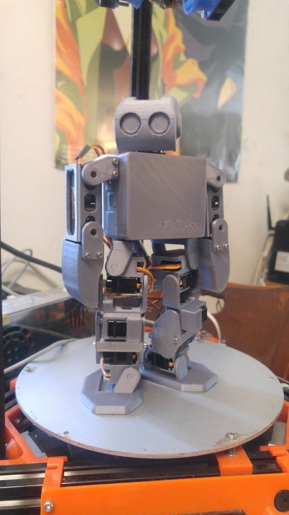
Kenny's Humanoid #3, The Miniplan
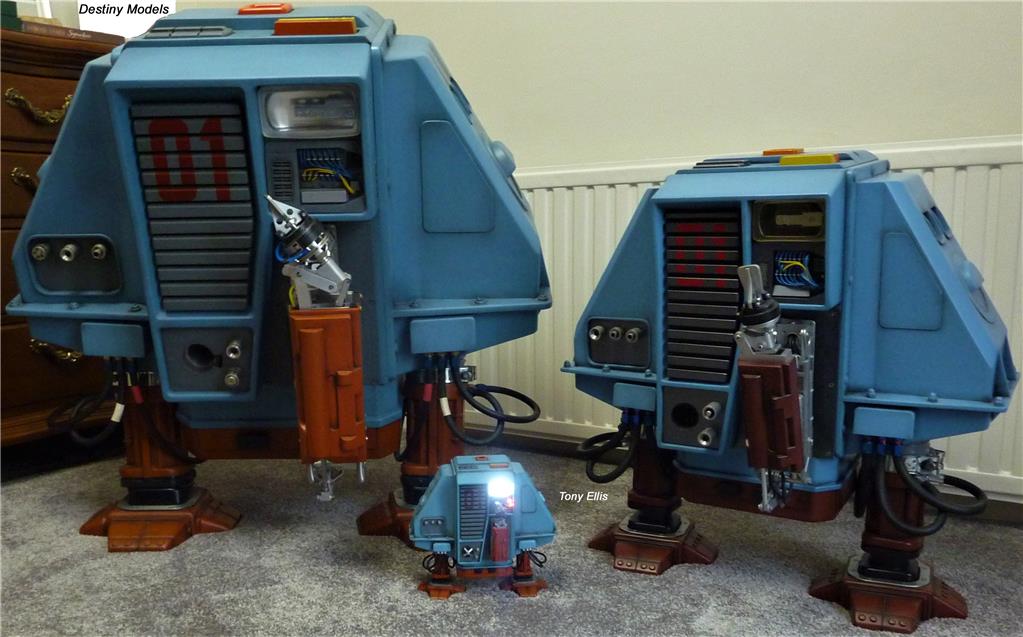
Toymaker's Dewey (Drone:1)

Step One - the wheel track assembly.
I think it's important to keep this intact so that the major mod of changing out the motors can occur without changing much else - the rigidity and stability of the tracks and the fixing to the hull are one thing you should not have to re-engineer. Not straight away at least.
This is the first big trick of the toy design - a key fixing screw is hidden in the axle of the driving wheel, under a stiff rubber cap with the B&L logo. Prise this up and you should see a screw down the axle. Remove the screw and the outer driving wheel should come free.
There are three more screws fixing the track assembly to the body - one is a little hidden, but it's placement is plain here with the assembly is removed.
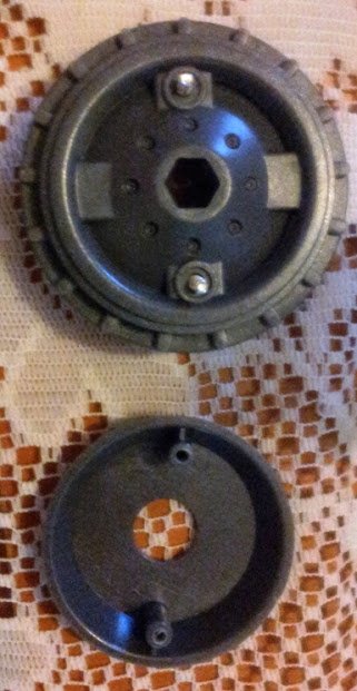
The inner driving wheel should just slide off the hex key axle, exposing the shaft from the inner gearbox.
The inner wheel has a cap on the inner surface which is held on by two screws. Disassembly of the inner wheel gives you the option to attach the driving hub from a servo, as seen in DJ Sures' gallery. (https://synthiam.com/Robots/The-Real-Wall-E)
The odd thing with this wheel is that the cap covers a detailed design on the wheel that looks like it should be the side that is exposed - it's not - it gets covered forever by that cap.
Step Two - in through the back door
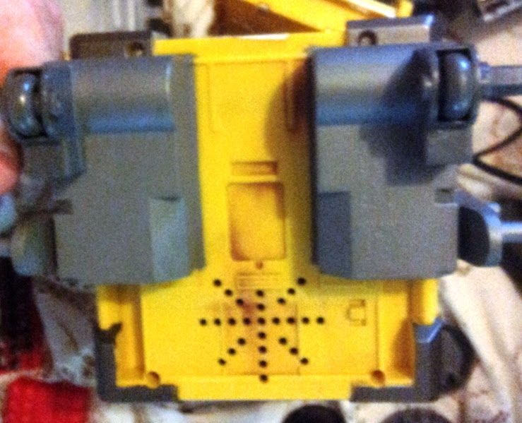
With the battery cover removed and the batteries out, the back panel should show four "security" screws of the new-fangled three blade screw type. A bother to get out without the right tool, but these are the only four of these you will see on the whole toy.
Inside the back plate, the first of two infrared sensors to be unscrewed.
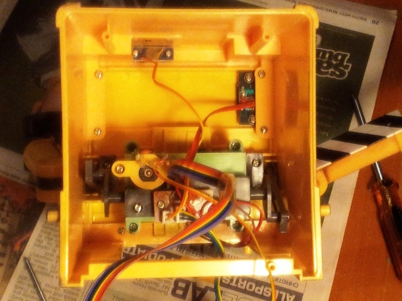
From the bottom of the toy, four screws hold the base plate to the body - unscrew these to remove the bottom.
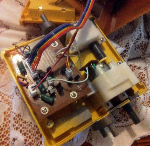
This bottom tray holds the motor and gear boxes that drove the toy and a circuit board, power switch and speaker. Unscrew and remove all of these.
The four plastic pillars which held the circuit board can probably be cut away unless you want to mount something else here. I found that these pillars were in the way of easily tucking the ez-b and battery pack inside Wall-E for testing.
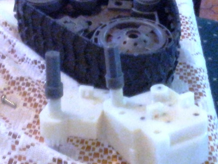
Above the drive shafts are slotted pieces which might be good to keep if your mods don't cut away the surrounding plastic (but most I have seen do.) The gear boxes themselves are probably not much use - the one without the motor does not reverse.
But you will need the plastic drive shafts from the gear boxes. They come off with some difficulty - opening the gear box and using a vise to clamp the piece while applying some pulling power to the shaft should do the trick. (No - don't re-read that last sentence.)
The resulting plastic shaft piece must fit inside your inner hub wheel when assembled - some of the shaft may need to have the thicker section trimmed or cut completely to go back in the socket of the wheel - glue may be needed to fix this in place - the correct depth can be determined by checking that the outer wheel fits correctly.
JOC
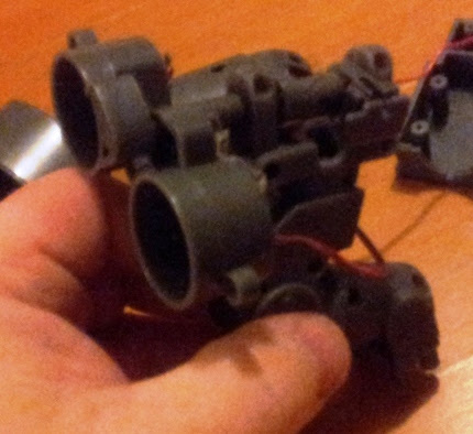
Step Three - up the guts
Viewed from below, Wall-E's insides should show 6 screws holding the body case sides (all one piece) to the top. Remove these and withdraw the top from the case - arms and gearing should all come out with it.
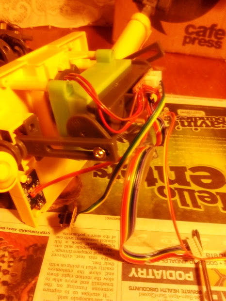
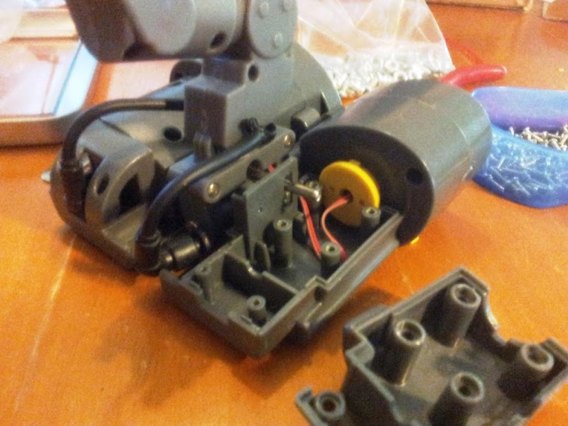
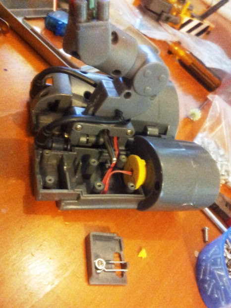
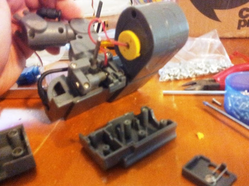
There is another gear box and motor for moving the head and arms. Almost all of this can be removed, except for the final brackets holding the arms on either side. Just remove the two screws from the end of the wheels at the end of the driveshaft connecting them.
From this gearing, I re-used the bottom of the gear case and the wheels from the ends of the shaft.
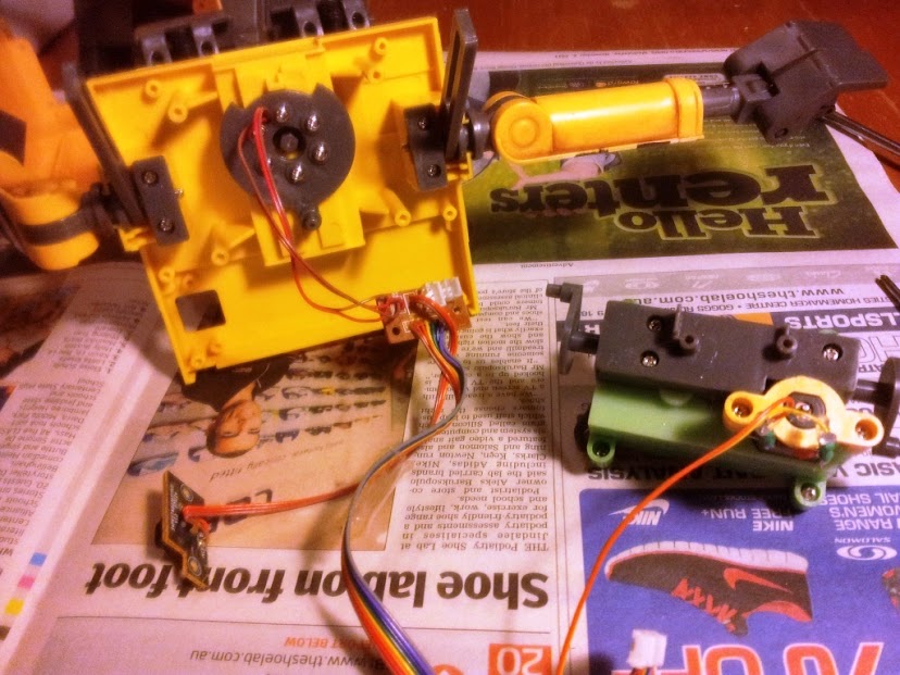
I am using these with two mini servos to work the arms with no exterior changes visible - inspired by this project - Djandco's Wall.e
The plastic wheel and bar that moved the head horizontally might be useful up in the head too ...
This assembly provided some elaborate gearing to do not very much at all in the toy, to give some "character". The motor drive moved the head and the arms and the eye-fold action in the head more or less randomly, but not truly independantly. The eyefold mechanism is driven initially by the hex drive in the centre of the neck and from there up through the neck in gears and shafts to a T-bar arm, pulled up and down.
I guess that must all be cheaper than a few more motors and some logic.
Another infrared sensor can be removed from the top, but I may re-use them at some point - not to control Wall-E (because discovering and programming the codes might be tedious) but perhaps just to get him to react to other infrared controls as stimuli might be amusing.
The "wake-up" press switch is probably worth keeping in place - I am sure that it could be used for something - possibly power on for camera or even just another stimulus trigger.
The base of Wall-E's neck is visible at the case top - remove the six screws holding it on. Some collar pieces come loose too - keep them.
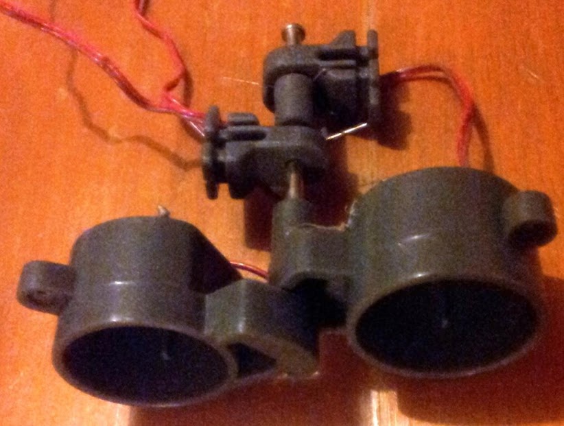
Step Four - pain in the neck
Lots of screws to undo here in the neck - but you can't get at the last two at the top.
For those, you will have to open up the back section of Wall-E's left eye, and remove it. The bottom shell comes away easily, but the top is held by a plastic plate piece that the "eye-fold" bar draws down and a hinge piece from the central shaft. A spring arm will likely pop free too.
Now the top neck screws are exposed the top of the neck should come away from the central shaft pivoting the eyes.
Here's the neck assembly showing the gearing (and my foot for scale. My Wall-E is huge.)
All that to fold his eyes up and down when the neck inner shaft is turned this way and that.
The other half carries the wires for the LEDs in his eyes.
JOC
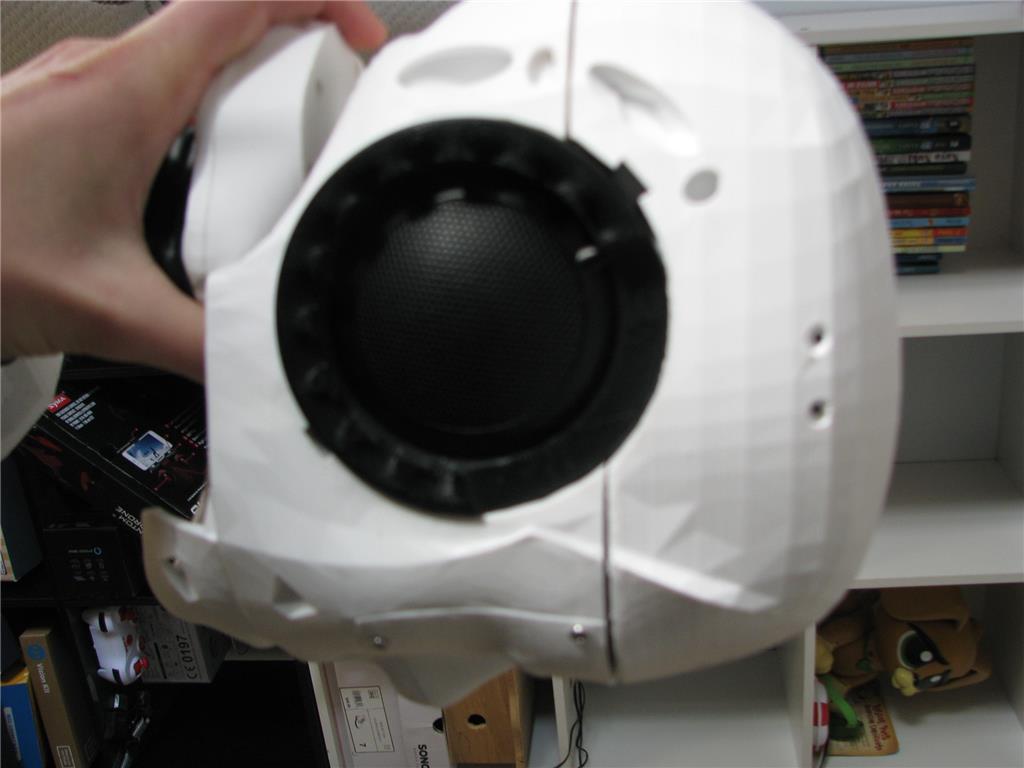
Step Five - the eyes have it
The eyes are by far the most convoluted assembly.
Each side has two major parts, each with a hinge attachment to the central bar that was in turn gripped by the top of the neck.
At the rear of the front section of the eye, the yellow cap is keyed to lock into the rear section, making each side rigid enough that the "eye-fold" action effectively treats the whole head as just two big pieces.
It would seem to be much simpler to have molded two whole halves and moved them that way. But the design does present a few options for modification - make the two halves single rigid pieces by glueing them and cutting out some internal plastic; alternately make the back section flat and rigid while leaving the front free to be animated.
Most modifiers will want to put the wireless cam in one eye at least, and some projects have a mini servo in one or both sides.
Two screws hold the front eye section together, and inside, the yellow cap is screwed in place on the back half of this section.
On the front section of the eye piece, the first example of something glued not screwed in place - the back of the eye LED fitting.
Two more screws to remove this inner eye-socket.
A smoked lens comes free from the front and the socket itself is filled with a plug of packing plastic, that helped diffuse the led for that even blue glow.
It is this eye-socket piece that directly hangs on the hinge bar; the rest of the eye front piece encasing it.
The eye "skeleton" assembled without the cases and mounted on the neck.
And that's it - he's all pulled apart - putting him back together is up to you.
JOC
Thanks fella this is really helpful
moar!
I have fixed up the photos that were only linked to thumbnail previews above.
Also - a few pics and things from my Wall-E rebuild - Joc's Ucontrol Wall-e
JOC
Im having trouble prying the cover off the hub screw in the very first step. Mine seem to be plastic and not hard rubber and are apparently glued in. Anyone else have the same issue?
Update. I gave up and I went in with a drill through the hub. Turns out my particular Wall-e didnt have a rubber cap I could pry off. It was plastic and glued in. If anyone else has one like mine and cant pry off the B&L logo cap on the axle just use about an eighth inch bit on a dremel and go straight in until it gives way. Its hollow. Now use a small phillips head screwdriver and take out the retaining screw. It will be exactly in the center and under the hole you drilled. Hope that helps those in similar situation.