Other robots from Synthiam community
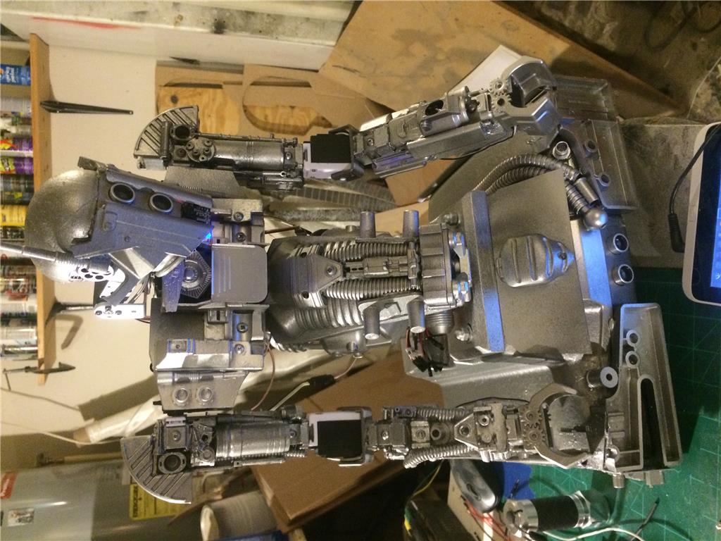
Bmcnamee1's Extending Jd
We have designed and 3D printed pieces with both a male and female parts, that connects in between the servos to make JD...
DJ's I Shall Call Him Norm
Norm is a very fitting name, no?
DJ's ARC Overview
The ultimate robot software ARC is leading the way for the next generation of robotics. Heres a short video I put...
You have Eve and the Apple, where's Adam ?
:)
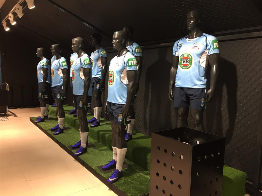
I think it's a good idea for window display although the price is prohibitive.
That's a neat idea for interactive clothing displays. I really like that idea and hope this business product works for you.
To start, it may be useful for video demonstrations which will provide visual example of how the product looks in a retail setting. If you could locate a local clothing retail company to be your test pilot, that would be a good start for a video.
Having the robot move into different positions or follow motion through the display glass. Or introduce the outfit and explain to the user with a recording why it is comfortable, etc...
Or even have a tablet control the robot so customers can pose the outfit manually to see what it looks like.
I remember to see a youtube video they used a few mannequins, some sensors and or cameras to create an interaction with the shoppers.
It was very cool.
Thanks for your ideas guys. I don't think the price is prohibitive. It would come with a warranty. I wanted to sell them for $2500 when I began but I was dreaming. I've spent thousands of dollars and thousands of hours on it. Even now, each one costs me around $6000 to make (not including labour). Shipping parts from the United states and our bad currency exchange rate as well as import tax make the costs add up. Some parts take 8 weeks to arrive from China. My parts are 3D printed but I want to make them either aluminium die cast or injection moulded. There are around thirty housing pieces even without legs and fingers and faces. Each mould costs at least $15,000 to get made before a single printed part has been fabricated. To make these en masse I will need hundreds of thousands of dollars. Think of how much Zara and giant retail outlets spend on signage, not to mention fashion shows and expos. These robots will have swagger when I finish with the hip rotation and legs. And yes, I'll definitely make an Adam. He'll probably be a fighting robot in some kind of Arena Wars gambling situation. I'm still tweaking Eve at the moment. I wouldn't mind making a few for Disneyland, either. The pan servo gears are difficult to centralise in a 60mm cylinder. That's why I've commissioned new servos to be created from scratch with centered shafts and other cool features.
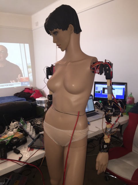
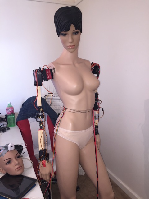
Here are some mannequins who aren't even dancing. Let's cheer them up.
Earlier prototypes:
Noise levels: https://www.youtube.com/watch?v=t_racaVZKNc&feature=em-upload_owner
Replacing desktop computers with a household butler and a projector screen is the ultimate idea. I'll use pandora and allow the online community to vote on a growing library of responses.
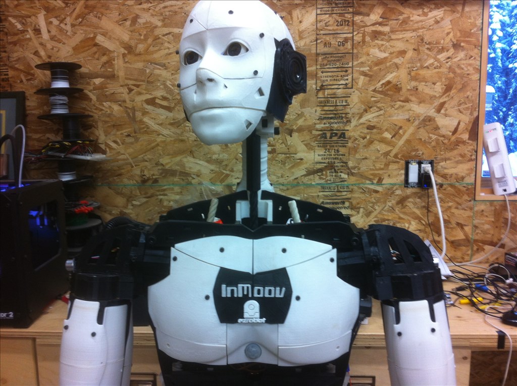
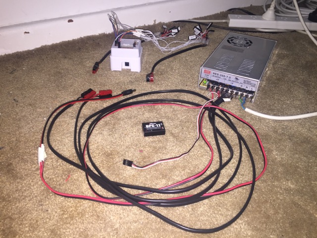
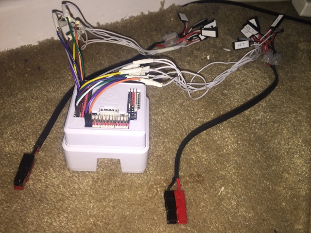
Here’s the wiring system I have used for my robomannequin. Here’s a year’s research summarised into a single page.
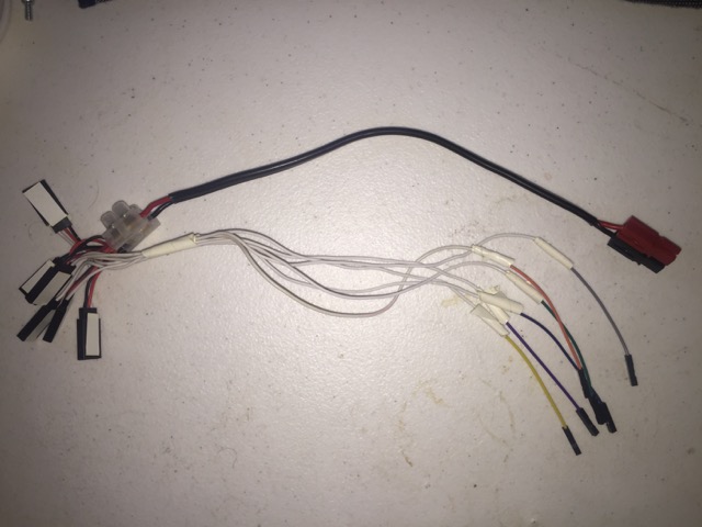
Here is an adapter cable I needed to make for a six servo arm. It includes 6 male PWM ends, 6 female single data cables and a 15A powerpole connector.
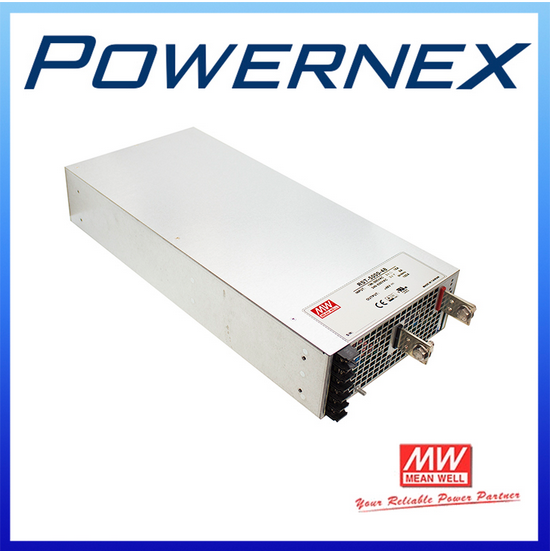
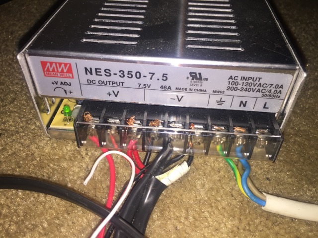
To power all the 7.4V servos in my robot that each peak at around 3A max, I use a Meanwell 7.5V46A power supply. I have attached two 15A powerpole connectors for the servos, one round connector for the EZBV4 microcontroller and a female servo cable to plug into the DPC-11 and DPC-10 servo programmers (they allow me to reduce the maximum servo speed to slow the robot down for safety and to prevent smashing).
The Meanwell power supplies do not come with safety cases, meaning I’m always exposed to 240V electricity. At least this one comes with a little plastic shield. To shut it down, I need to rip it out of the wall socket.
I’ve had to label both the wires coming out of the robot and the adapter ends so I can re-assemble the system. The colour coding is somewhat useful, but the colours do not exist anywhere else so the colour coding is somewhat useless. There are only seven colours in the rainbow and red and black would be confusing, for data wires, so any useful colour coding would require several colours or patterns instead of solid. Importantly, you can see that only one data wire is required in this case (data signal sent one way from the microcontroller to the servos) rather than needing the red and black power wires from the servos to the mc. The mc is controlled via a Windows PC initially via a WiFi router, then from my iPad, game controller or VR headset. All these methods of control are vastly inferior to the capability of programming by posing the robot (which requires a receive wire from each servo to the mc). This particular microcontroller, the EZB version 4 from ez-robot.com shuts down easily due to excessive current. Also, accidental contact from a charged servo wire has often resulted in short circuiting (my bad). Wiring is important and needs to be neat, safe and thought-free (intuitive) for the user. The adapter cables I have had to make to bypass the mc power pins and go straight to the power supply should be commonplace but I do not think they even exist commercially yet.
I am currently commissioning servo modules that will run on 12-24V, include internal holding brakes, have centered shafts and click together like leggo. They will have infinite rotation but will rotate to an exact position, even after thousands of rotations. eg. Rotate 10,567 degrees. They will daisy chain using I2C rather than PWM, they will tolerate a chain of up to 100Amps, and they will have bi-directional send/receive data lines for pose-frame programming.
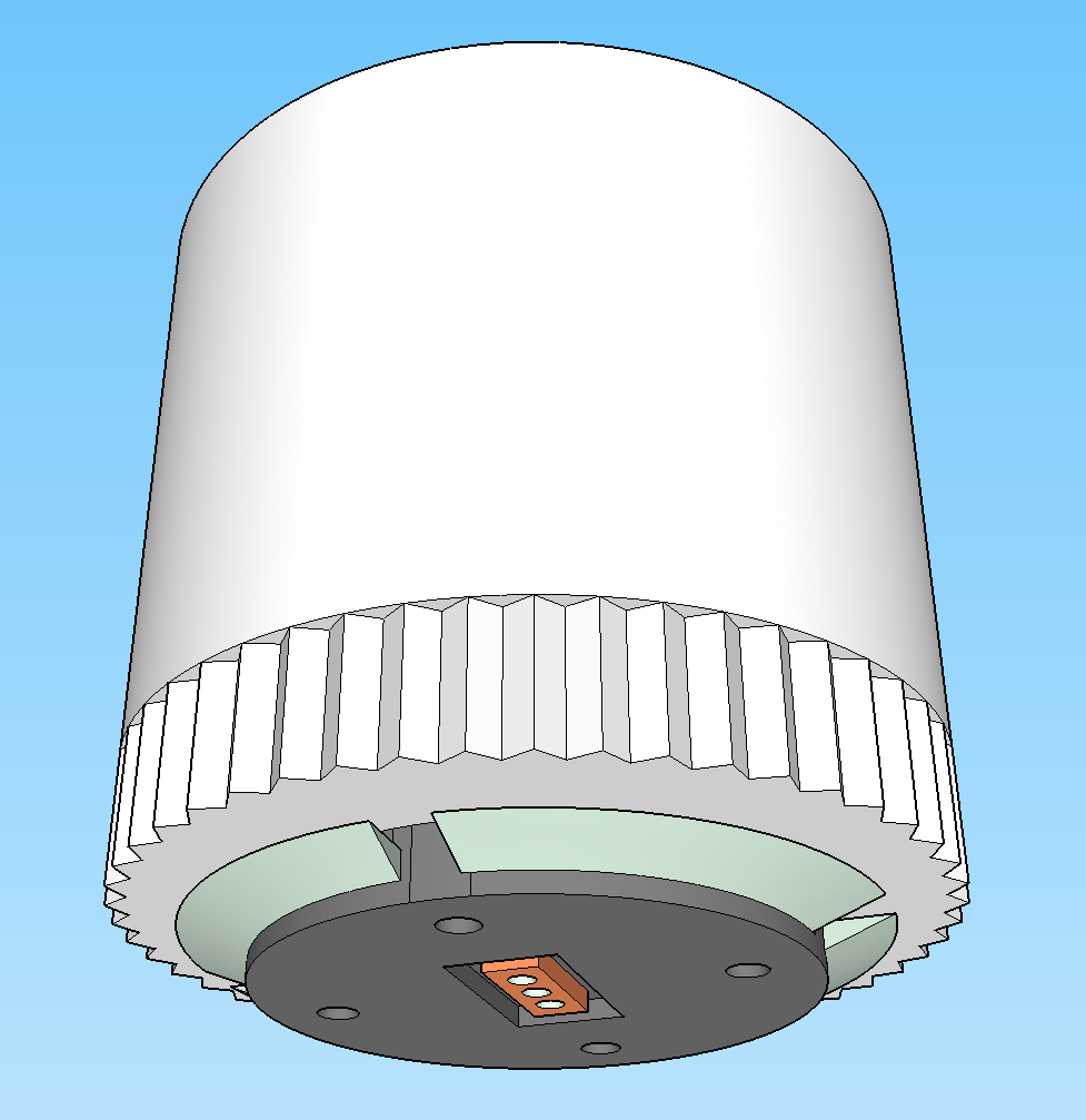
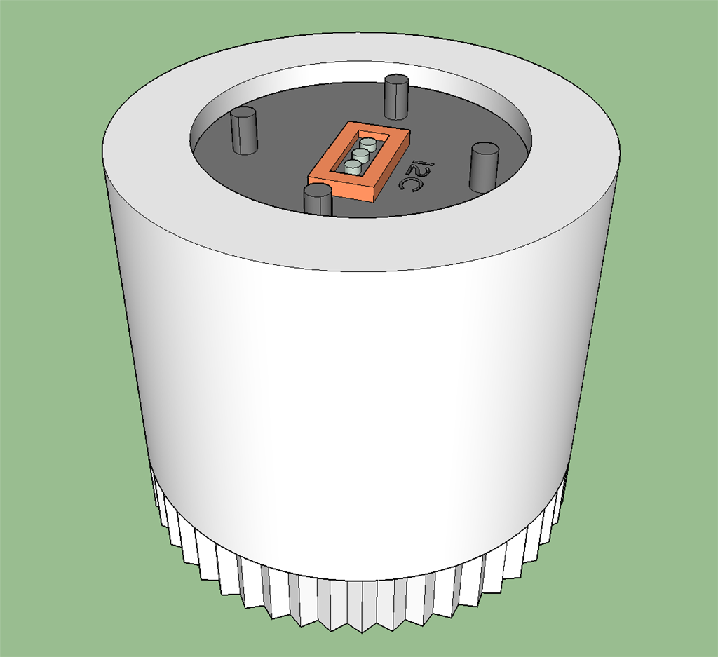
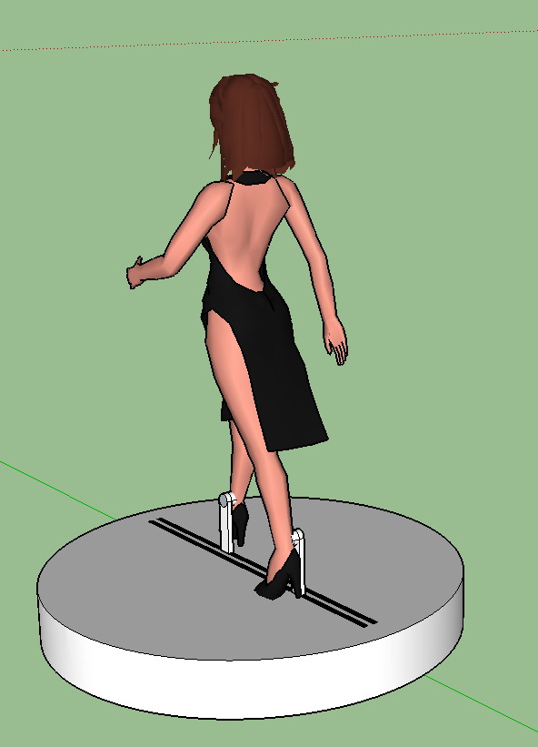
Here's a vague mockup I made for my mechanical engineers to get an idea of the outward appearance of my servos. This design does not accommodate bevel tilt hinge modules, so it will be refined.
These servo modules can be scaled up, so can replace car engines by placing electric motors in the wheels. They have hobby, medical, aeronautical, hospitality, mining and industrial applications. Servos are only one type of attachment for these robotic modules. You will be able to build such things as a walking dinosaur, an exoskeleton, an intelligent crane, a motorbike or an autonomous drill to create a network of underground roads (undergroundroads.com) by clicking pieces together. We will work on programmable gearing too, so there will be no need to buy different servos for speed versus torque.
@Zxen,
Impressive work.
Regarding the prohibitive cost, ignore it... There's a lot of work, research, trial & failures so you more than anyone knows the right value.
The mortar and brick stores are facing enormous challenges, less foot traffic, online competition from pure online retailers (e. g. Amazon ) , no community shop spirit (support the local commerce), shoppers with less time for store shopping, etc etc. In other words and generally speaking the traditional retail is agonizing and dying, for most small and family businesses the mannequin cost seems high.
The retail major league e.g. department, high end destination stores the price is not the first factor and there's demand for unique & creative solutions, more robots and cool stuff.
@Zxen Dude, I hope you have liability insurance. From what you have created here I am not sure all those off the shelf hobby components you've slapped together are not a fire or safety hazard... No offence but lets hope your mechanical engineer is also an electrical engineer.... True you have done a lot of work but I am going to say you probably will have trouble convincing brick and mortar stores to buy something that wasn't created and made by a large company with proper engineering and consumer safety testing standards. Not even sure there is a market anyway for such product. Moving manikins are the stuff of horror movies, aren't they? LOL. ... Anyway, Sorry just my honest opinion but good luck...
Good sales pitch, ptp, hadn't thought to frame it that way.
Yes, Richard R, it is not ready. I will find the money, even if I have to rent them out for a while and pay for liability insurance. I might go to kickstarter as well. The poster I placed at the beginning of this article with the prices I have only shown to you guys. I'm glad I did because the feedback is really useful.
DJ Sures says i2c is no good for the servos I'm developing and I should use UART. I can only afford to do it the right way. I'm meeting the engineers on Monday. What do you guys think? Has anyone plugged a daisy chain of servos into UART before?
Dynamixel servos use serial communication (UART) and can be daisy chained. They are not cheap, but they have a lot going for them, including position feedback.
Serial communication is a very old, very well understood, and very stable protocol. Search google for i2c EMI or i2c interference, or i2c issues and you will find a lot of discussions about how it can be difficult to get right.
If you are working with electrical engineers, those issues can be overcome, but I wouldn't put MY money on the line using that protocol in something I planned on selling (using it for my own robots, where my tolerance for pain is higher is a different story).
Alan
So of all the 'protocols', whats your vote?
@ZXen:
this statement worries me:
First of all i'm not an electric engineer, and most people here provide their opinion based in user experience or based in other's opinion (Internet, EZ robots tutorials, posts etc)
Is a very high risk decision to decide whatever direction based in our opinions.
Common sense says "the correct solution is the one it works", but that is not so simple.
If you are building a solution/product to work with EZ-Robots hardware e.g. EZB Controller, ARC and you have doubts, and you want to be 99.9% sure the solution will work you will need to discuss that with EZ-Robots, probably an offline discussion, and get some kind of agreement about which path is the one will work for you with EZR hardware.
I've been in different forums PIC, Arduinos, Propellers, Raspberry and EZ-Robot, and each forum there are conflicting opinions.
One will say SPI is the best protocol, other will say is not.
The reason why SPI didn't worked for a specific micro-controller was an existent bug on the micro-controller plus some low level software limitations.
So most people on their forum (including the company evangelists) said SPI was not the best protocol, and brainwashed everyone.
Coming to EZB does not matter if SPI is best protocol, EZB does not support SPI, so people here (myself included) will endorse Serial, or I2C.
If you have a better experience with Serial versus I2C and you don't know why or is not simple to fix the issue, you will say Serial is the best and safest bet.
I'm not saying which one is better...
to make it simple we are all biased
Next post i'll give you my biased opinion.
Thanks for your wisdom. I don't understand the terminology. Today I've learned the word 'protocol' and have now heard of a lot of them without knowing anything about them.
Lots of people say i2c is 'quirky' and problematic. DJ is successful and breathes this stuff and suggested UART. I've only dealt with PWM so I know nothing about all the others.
I found a video about some of them: https://www.youtube.com/watch?v=5y4NMzjLXus. This instructor uses the term 'interfaces' instead of 'protocols'. Also, he is impartial and seems to dislike i2c.
The EZB-V5 will probably have more ports if I choose something that doesn't exist on the V4 yet because DJ keeps adding stuff (and hopefully the gigantic power base won't exist any more).
Servos protocols:
allows daisy chain some examples:
RC PPM Streams: http://rcarduino.blogspot.com/2012/11/how-to-read-rc-receiver-ppm-stream.html
Hitec HMI Interface: Extended Pulse mode to add position feedback and change settings Bidirectional Serial Interface at 19200 bps
currently EZB only supports single servo PPM
http://support.robotis.com/en/product/dynamixel/dxl_mx_main.htm
Dynamixel servos use a half duplex serial communication using a trisate buffer is not a full duplex serial protocol.
2.1) Dynamixel servos AX family uses a single data pin.
EZB supports dynamixel servos
2.2) other dynamixel servos requires 2 pins (data+, data-) i believe the data- is a inverted data+ signal, allows longer cables, and error correction.
I'm not sure if EZB supports these.
http://www.robotshop.com/en/herkulex-drs-0101-robot-servo.html
Similar to the Dynamixel, 4 pins and Full duplex UART (RX,TX)
if is a regular uart, you can connect to EZB and via plugin emulate a V-Port (DJ's Tip)
Openservo specification is based in I2C protocol:
https://www.sparkfun.com/products/retired/9014
The board is retired, i think the reason is a niche product, you need to open your servo, take the board off, replace it etc. Is not so easy.
if a company like Sparkfun invested time and resources to build and sell, there is potential, but looking to the comments, you understand is not so easy to support, basically because there are so many servos in the market and some are good, other not.
They have the specs open.
My opinion:
i like I2C protocol, probably because it's so simple and allows multiple devices.
EZB + I2C:
based on my user experience, and others opinions EZB does not deal very well with I2C errors (bad wiring, protocol errors, invalid responses etc), and if the EZB gets stuck you need to unplug the power (reboot via browser does not work).
so if you want to avoid issues you have two options:
choose another communication method: Full duplex Serial, well endorsed by the EZB community.
add a micro-controller to handle low level I2C communications and the micro-controller communicates with EZB via Serial, and if does not work blame the I2C or the micro-controller code, or the wires except the EZB
BUT based in what i read so far, also sharing Richard concerns, i think is high risk move, design specific hardware when you don't have space/investment for errors.
I would first study the Dynamixel & Herkulex, although they are not cheap.
*** Disclaimer: I'm not an electric engineer, neither professional roboticist. I only play with robots and hardware outside my work (Software Developer) and when my kids let me.
Thanks so much for all that info! I am spending thousands of dollars making new servos, so I need to decide the easiest and most reliable daisy chain system. Mine will look more like this:
We will be using a magnetic encoder rather than a potentiometer for infinite rotation. The peak current may be around 10A per module because we might use dense rare earth magnet DC motors for extra speed and torque. I had I2C in mind because a robotics guy recommended it to me over PWM. The wiring for power will cater to 50-100A and run directly through the leggo-connected daisy chain of servos and any other connected modules, straight to the power supply so the EZB doesn't say, 'My battery is low' until the world ends. The data lines will run to the EZB or another board. I would like to use the EZB but I'll probably trust the mech. engineer at the end of the day. I sent him an email to say UART might be better. I've also just learned of TWI, USART, and RS-485. How many are there?
The terminology on the three videos I just watched was way over my head. Are 'protocol', 'interface' and 'peripheral bus' all the same thing?
Also, will we need to make our own circuit boards for the servos or can existing ones be bought easily? My mechanical engineer suggested making one but its more time and money. I figured they could be sourced easily enough?
https://www.youtube.com/watch?v=e8uEKWpVf10 Atmel AVR microcontoller chips are used in Dynamixel servos. That might answer the question of whether we need to create our own chips or simply source them. This video explaining UART is really good.
I think is a little of both, and depends on the perspective.
Interface is more related to the hardware or component side, if you don't know the protocol i would say the interface is one wire or two wires.
When you mention protocol implicit you will know how many wires you will need.
peripheral bus: means an external bus to connect devices
SPI (Serial Peripheral Interface) the master controls the clock/speed requires minimum 3 wires: Clock, MOSI, MISO It's a single master multiple slave BUS each slave device requires a slave select wire: 3 devices = (3+3), 8 devices = (3+8)
I2C (Inter-Integrated Circuit) the clock is predefined: requires 2 wires only: SLA, SDL is multi-master, multi-slave BUS device each device has an address.
Serial Communication: the clock is predefined: Full Duplex - 2 wires: TX + RX Single direction: 1 wire (Tx->Rx) Half Duplex - 1 wire (e.g. Dynamixel 1 Data pin) Half Duplex - 2 wires (e.g. Dynamixel 2 Data pins - Differential Signaling) RS485 Full Duplex - 4 wires (RX-2 TX-2) RS485 Single Direction: 2 wires (TX->RX)
You will need to design your pcb and the circuit, building can be outsourced.
Don't minimize the work and the know how you will need to build your own servos.
I won't be building them, the company will - I just need to understand whether too much time and money is going to be spent unnecessarily. If dynamixel use existing chips that they've plugged in, then surely I don't need to go out and create new chips. The video told me they use Amtel AVR chips. I don't know if thats just one component of the circuit board.
You are very knowledgeable. I've watched a couple of scary too much information videos just now. One of them was about half duplex, but I needed pre-requisite knowledge so it was way over my head. At least Im beginning to recognise words. I also thought that 10A was really high draw for a servo but Ive discovered that its common for 12-24V servos when bearing a full load. The power supply and wiring will need to be massive to cater to all this current. My robomannequin uses only 15 servos but at 10A each, the power supply for this basic model would be 150A. I don't need that much power for a wrist or elbow so hopefully it would use a low current for light things. 24V at 10A would give you around 44N.m with low speed gearing. But considering weight bearing usages such as a human crane in a hospital, they need to be rated to lift 500kg. 44 N.m equals about 450 kg.cm torque. A full robot with legs might need 30 servos. 30 servos x 24V x10A = 7,200W power supply.
Even a 24V 200A 5000W power supply costs US$1100 before currency exchange, delivery and tax, they are large and heavy, and the electricity bill for switching on the robot could be very expensive for the user. I'm hoping it hardly ever needs to draw that much current unless its building a car or a house. https://wholesaler.alibaba.com/product-detail/-PowerNex-Mean-Well-RST-5000_60490236130.html?spm=a2700.7724857.0.0.ipiidV
These specs on the Dynamixel Pros give me some perspective. https://www.youtube.com/watch?v=rmqyOCefhGA
Due to compatibility with EZB and interchangeability with Dynamixel peripherals, I'm leaning towards UART at the moment. Even UART is complicated. PPM seems the simplest.
Hey guys, I really enjoyed this topic about communication types... I never really got into all the different Interfaces, seems to be worth exploring!
@Zxen good luck with your project, seems to be a major thing building and marketing it! Hope you'll find the right peer group once it is ready to go!
You should read up on the new Dynamixel Property servos.they are not round but have inline body and shafts configuration.. Go to Robitis.com. Theven servos might interest you for your project.
One solution to the problem of pulling so many amps and needing to buy a "super" power supply is to run your robot off several smaller power supplies. Don't tie them together in series to boost the amp capacity because that won't work. You will have one or two hog the load. When running several ps's on the same robot you need to run them in parallel and manually distribute your load among them. For example run one set of arm servos off one PS and the other arm of a second. Then you can have a third PS dedicated to other devices like audio. This also helps with electronic noise. If your audio is picking up the whine of servos or motors moving or the click of transistors turning on and off lights you can run them on different PS's. Just don't tie the DC side nutrials or grounds together because this noise runs on the nutrials.
Dave, if you aren't tying the grounds together, do you need a seperate EZ-B (or other controller) for each power supply as well? I thought you needed to tie the grounds of the servos (or h-bridges) to the EZ-B as a signal reference.
That might be a good idea for a large robot anyway, basically set up each group of movements as independent subsystems, but does add to the project complexity.
Alan
Ya, Alan, grounds and neutrals are hard to figure out sometimes. tired There are time when separating grounds are a good idea. I'm sure you've heard of ground loops. eek These can turn into a nightmare. Then, some devices require shared grounds so they operate together like the EZB ans other micro controller and the motor controllers they operate. Then with other devices, if you tie the grounds together you do end up transmitting electronic noise to places where it's not welcomed. Electronic noise will be apparent right away in an audio system. I'm sure most have heard it clicking or humming away in the background of a sound track or music. Here you would want to isolate your sound system from the device causing the noise if possible. Feedback devices also suffer from noise and may affect your controller because it will transmit less accurate info. With these devices you may end up adding extra grounding to bleed off the noise. Wiring electrical circuits to power electronics is tricky and requires forethought, planning and maybe even some trial and error. eyeroll There's never an easy answer is there? LOL
Why do little toy servo motors need hundreds of amps? The wall socket only gives me ten amps and I'm running an industrial fridge, 2 3D printers, a projector, a 4K tv, a kettle, an air conditioner and all the lights in the house. Something seems majorly wrong here. How many amps does a car use? A car would definitely defeat my robot in a game of tug of war.
My original idea to keep the arms light was to have a bank of servos in the torso and run bicycle cables pulling against springs. Has anyone done this?