
Well, after a month of waiting for parts, a week of building a base, and a week of runnning wires and reading your community posts to ensure I don't set something on fire, Dopey came to life and made a couple of complete circles in the middle of the room.
I've captured many pictures over the last two weeks, and while he won't win any beauty pageants, it has been fun, and in the interest of sharing the experience, I'll be posting some pictures and commentary over the next few days.
-John
By jdmarsh50
— Last update
Other robots from Synthiam community
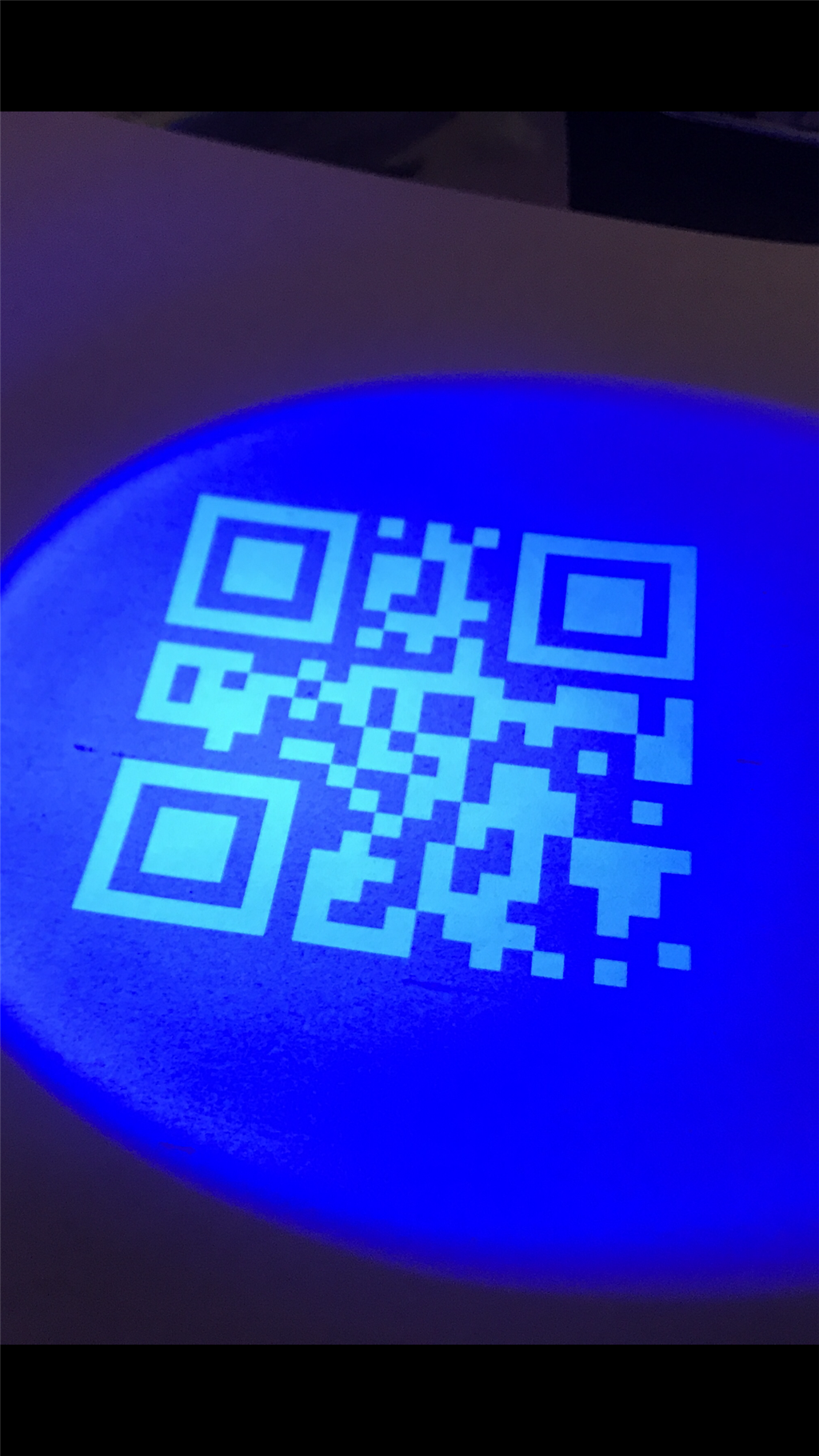
Jstarne1's Invisible Qr Code Project For Hackaday...
Custom invisible QR codes for discreet home marking visible only under 405nm UV or 780nm IR light; EZ-Robot compatible

Steve's Lt. Commander Data's Child Lal
Lal humanoid house robot inspired by Star Trek TNG, powered by EZB4, EZ-Robot HD servos, iRobot Create drive and...
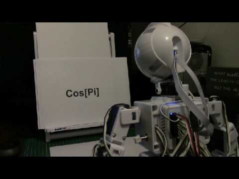
Tezsmith's Linking Mathematica (Computational Software...
Synthiam ARC linked to Mathematica enables robots to read text, identify 10k+ objects, compute routes, use WolframAlpha...

Cool I hope to see some pics soon.
Can't wait!
Dopey will be hand built, not from an existing toy. I knew I would be making many design changes as I built him, as I did almost zero planning on what he would look like. I know eventually I want him to operate both indoor and outdoor, be a couple feet tall, have enough battery to last a few hours, and eventually carry a computer to be autonomous.
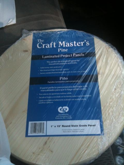
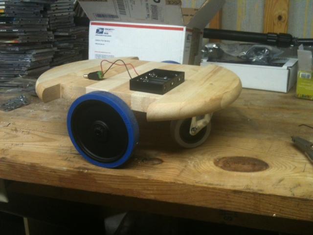
As a prototype, and anticipating the need to constantly move things around, I settled on a 15 inch pine circular tabletop, weighing in at 2.4 lbs. Cost was about 8 bucks.
(First time I have attached pictures. Hopefully I am doing this right).
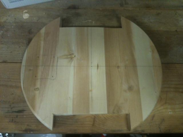
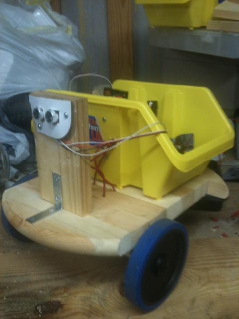
I did some trimming on it to create "wheel wells", and so here is what the base now looks like.
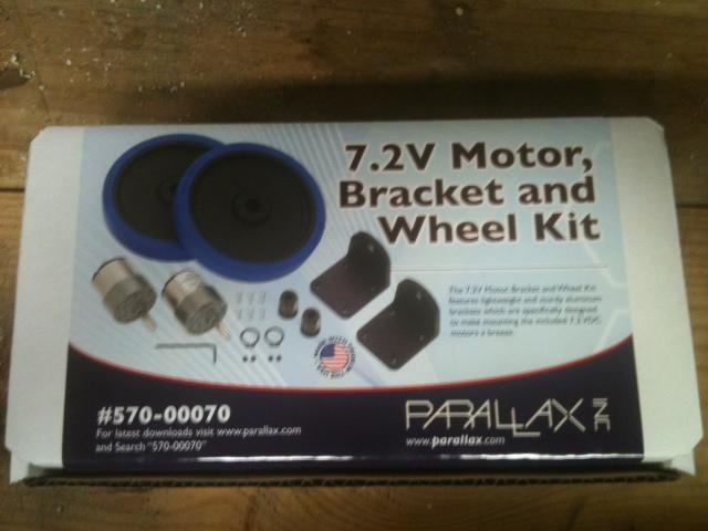
He'll run on 7.2 volt motors and wheels from Parallax. Kit is about 80 bucks and seems to be very well made.
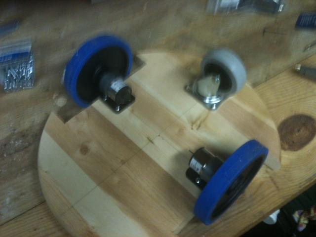
Wheels installed, and put a good loose caster on the rear. I have since added a second caster to the front.
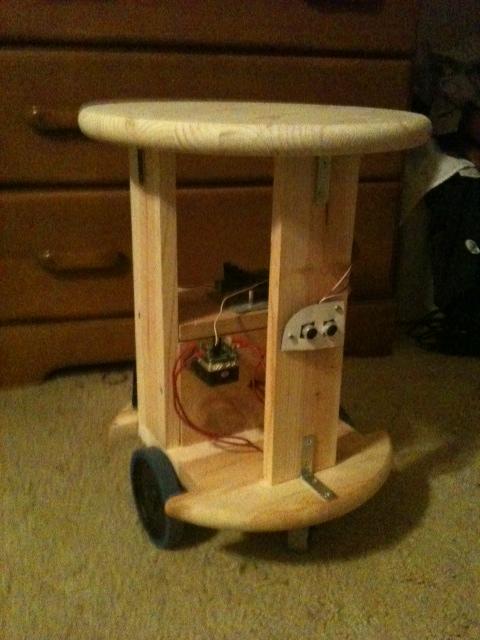
Here he is with the underside somewhat complete.
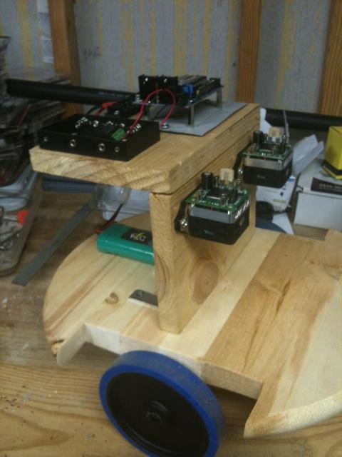
And finally, I added a vertical wall and a horizontal shelf. The EZ-Board will go on the top shelf for now.
More pictures tomorrow.
-John
Cool!
Very cool start. Looks like you are on your way to a fun robot.
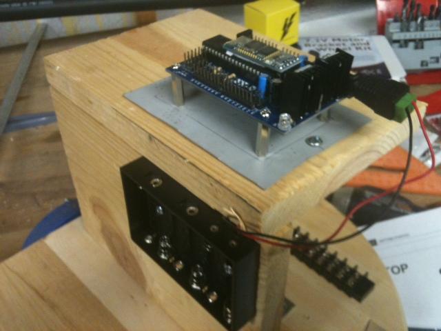
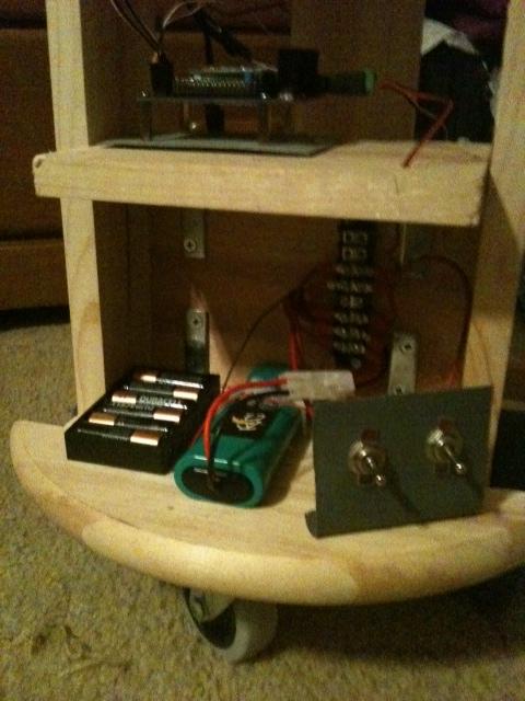
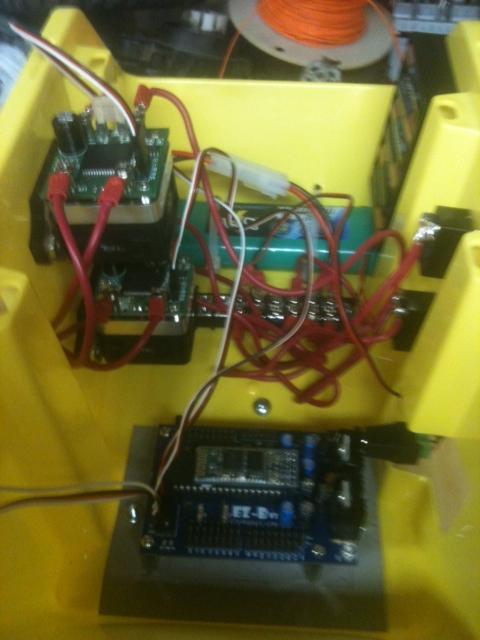
To mount the EZ onto a wooden platform, I cut a small piece of sheet metal, painted it, and attached 4 PCB standoffs. I mounted the AA battery holder on the front of the shelf.
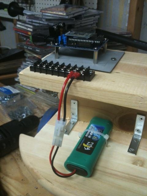
To the rear of the shelf, I added a terminal block for power connections, then attached a 7.2 RC battery pack with a quick-disconnect.
Two HB-25 motor controllers were added to the front shelf. I moved the AA battery pack up top at this point, as real estate was filling up quickly.
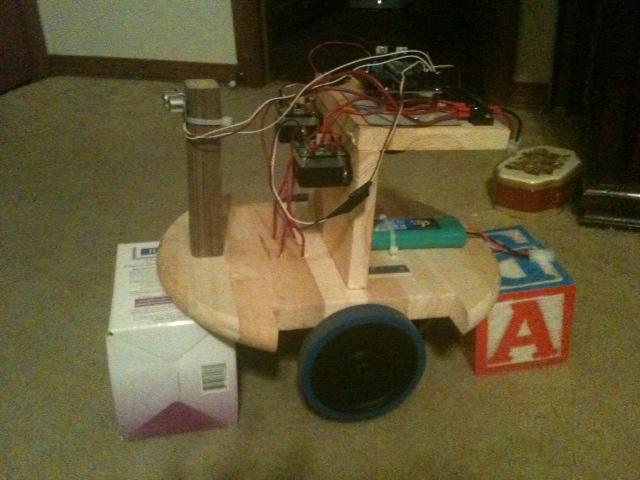
Wired in the ultrasound sensor, tie strapped to a small post added to the front. He is now on "blocks" so he can be tested without running into something.
Power checks were all good. Wrote my first 5 line script last night. Wheels are turning using the PWM tags; the values I am using are kinda weird, but they were the same values I had to use on the slider control the night prior.
So far, so good.
-John
Excellent! And super fast progress! That is the really great thing about EZ-B, how quickly you can get a bot up and running.
John,
Nice job so far. I love the idea of using the tabletop as the base.
Jim