Asked
— Edited

Wiring Up Lm1084 Regulators
Hey everyone.
Just making sure I'm correct on this, would this diagram be correct?
Thanks, Tech
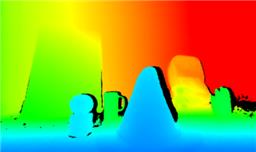 Kinect Xbox 360 Depth Mapping
— Converts Xbox 360 Kinect depth frames into NMS obstacle scans for ARC path planning, SLAM, and obstacle avoidance.
Try it →
Kinect Xbox 360 Depth Mapping
— Converts Xbox 360 Kinect depth frames into NMS obstacle scans for ARC path planning, SLAM, and obstacle avoidance.
Try it →

Hey Tech, I can verify that it looks good!
I have not used the 1084 but this is the wiring i use for 7805
I'm wondering why you are not using capacitors with the regulator between.
the blue bar at top will be ground and the red bar is regulated 5v.
Good call with the missing Caps @Luis
The LM1084 does have a different pinout than the classic 7805, it's more like a LM317 pinout
I have soldered dozens of LM7805s into servo extension cables... all without caps... They seem to work flawlessly with pings and other 5v sensors I have been using. I have even used them with micro servos... Why do we need the caps?
Caps are used for input line filtering and keeping the output voltage stable (less voltage sag) when in high current demand situations.
wow you guys are fast
I understand what a cap does... but with a device like a ping that uses such a low amount of current, would that still be an issue?
You won't need a cap As an electrical engineer, jeremie is trained to make everything super stable. However, the device you are connecting to the LM1084 most likely has a filter cap of it's own - otherwise i'm certain it isn't a microprocessor that you're running so it'll be fine