
V4 Servo/Sensor Power Board
Hello everyone
I know that the V4 has a direct voltage input from the battery to the digital pins. I was unsure however if this also incuded supplying direct voltage to the outer pin as well?
I was looking online to make something to where i can run my servos and or sensors at a different voltage then what was supplied from the board. I planned to run 12 volts into the board but realized I would need to step down the voltage in every pin that requires 7.2 or 5v. servo City sells a servo Power Board for around $20-30 and I was wondering if anyone had experience with using it. I think it may solve the problem of powering multiple pins at another voltage than what the board is supplying? It says that "cleanly power your servos on more than 6 volts and not burn up your receiver" I could be completely wrong in thinking that this may work so any thoughts would be welcome! It would definitely be a easier way to power things if this could work though

I like this... You could use that to power all your sensors that use 5V as well... Just use a ample 5V power supply in and the rest is plug n'play... I actually might buy a couple for this very purpose.... good find...
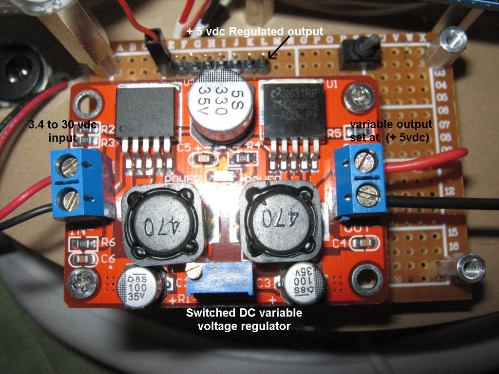
I built a switched 5vdc supply to power all the sensors that I will use to connect to the EZB4 by using a small blank pc board, a switched regulated power supply that has a variable output, up to 3 amps. The dc input can be from 3.4 to 30 vdc and the output can be adjusted from 3.3 to 28 vdc depending on the actual input and a 8 pin section of a header strip. All these goodies can be found on ebay or Amazon.
I also found a fused tamiya connector. obviously the tamiya plug can be replaced for the micro deans that the v4 comes with but this would allow us to get rid of the larger power box
fused tamiya plug
@Robot-Doc that is really cool! much like i was going to try to achieve but i think mine would have been 2 separate pieces...
Rich has made a DYI on a servo power board on one of his threads if you're looking to go a cheaper route and make it.
@Troy do you have a link by any chance
Details of it are in my Melvin project somewhere. I'll dig out the info... here we go
It's more of a distribution board than a power board though. Very simplistic!
thank you for that link Rich! that is actually pretty simple to just make yourself...
Yep. You could use pin headers too so that standard jumper wires can be used. In my example I soldered direct to the board but I've since changed how I wire things so pin headers are now the better option. I use something similar for I2C distribution on my V3.