
Andy Roid
USA
Asked
— Edited
There has been much confusion on how to add a relay to an Ezb. There are three style relays, relay only, relay with a built in transistor circuit, and a relay with an opto-couple circuit. I have the relay with an opto-couple circuit. (817C) ?
This relay requires a 10 K resistor placed in series with the digital output. It is programmed by using a digital output, and "Set Digital". The issue is when the signal sent is "On" the relay is turned off. When the signal is sent "Off" the relay turns on.
This operation needs to be accounted for in your design so relay do not come on during a start up.
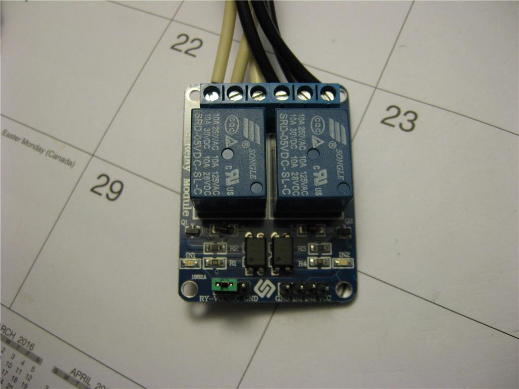

Hey @ANDY Do you mind posting a schematic /photo of how you wired the relays in conjunction with the tip120 circuit? How are you powering the relays?
I'd also like to know why you need the relays at all, if you have a tip120...just picking your reasoning
Hi Doom, The TIP circuit works fine, and operates the relays correctly. I built a circuit based on a thread from Rich. I use the contacts on the relays to operate in place of a pushbutton on a wireless remote. This wireless remote operates 110 vac remote outlets to turn on lights and a coffee pot. I do not have enough electronic knowledge to wire the TIP circuit directly into the remote, thus eliminate the relay. I don't want to destroy the remote control if I connect something wrong. I will check my papers and post a diagram of the TIP circuit for you.
I use the relays due to frustration ! LOL I was never able to get any of my relays ( I have three different styles and types ) to work. I was running out of time, so I just built the TIP circuit and used that.
Due to the latest threads posted, I pulled everything apart to try to get the relays to work directly with the ezb, again. A resistor in series between the ezb port and the relay lets it work in the inverse. This means I need to do some rewiring, add a master relay, and reprogram which is ok. This way I can eliminate the TIP controls. The other relays still won't work, but I will mess with them more later. Jeremie continues to post information. so I will continue to try things.
@Andy,
Did you tried connecting both D0 D1 to In1, In2 without resistors ?
Yes and no good. I found a second one and tried it with the same results. When I use the resistor, the leds don't work correctly, but the relay does. Maybe I will paint the leds black and forget about them.... LOL
I just finished drawing a schematic for the transistor style relay and posted it on the other thread, I will try to do the same here. At least with a drawing we may see how these things work and what is needed to operate them.
I will try to make the drawing now.
yes a schematic would help,
it's strange it's a very simple circuit.
Q1) regarding the resistors r2 & r3 you wrote 115 are you sure ?
Q2) can you confirm if the led is red ?
Q3) can you confirm the power supply VCC is 5v ?
this is what we have so far:
setup: vcc=power supply 5v gnd = ezb gnd + power gnd (common ground ) in1 = EZB D0, in2 = EZB D1.
above setup the relay switches on with EZB pin LOW, the relay does not switch off with EZB pin HIGH.
you add 10K resistor between EZB Dx and Inx
the relay switches on & off, but the led does not switch off (dimmed)
Sorry to repeat, but this is a KISS device .... so double checking
For r2 and r3 which may be 511 instead of 115 ( hard to see )
It is a flat led which is a red / orange ?
Power supply is 5 volts. ( it is able to power an 8 relay board and 8 TIP 120s)
Operation is as you described.
Here is the sketch for one circuit. I think it is right except for maybe the diode polarity.
The jumper is on vcc to vcc. gnd is open. (vcc's needs to be jumped)
Hope this helps...
I believe the connection between the coil, flyback diode, and 817C goes to VCC as well, correct? With the jumper on, of course.
*edit: Whoops this post was meant for @Andy's diagram