
Andy Roid
USA
Asked
— Edited
Using Opto- Couple Relays With An Ezb
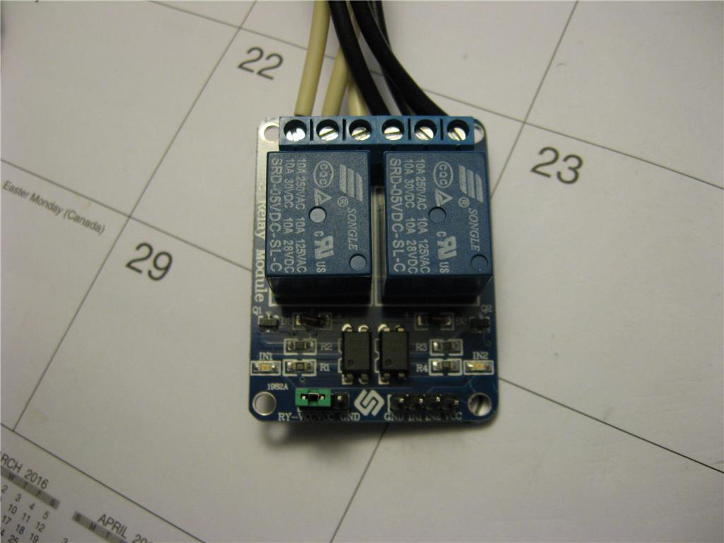
There has been much confusion on how to add a relay to an Ezb. There are three style relays, relay only, relay with a built in transistor circuit, and a relay with an opto-couple circuit. I have the relay with an opto-couple circuit. (817C) ?
This relay requires a 10 K resistor placed in series with the digital output. It is programmed by using a digital output, and "Set Digital". The issue is when the signal sent is "On" the relay is turned off. When the signal is sent "Off" the relay turns on.
This operation needs to be accounted for in your design so relay do not come on during a start up.

Thanks @rgordon that's a very classy diagram!
I Thank everyone....
At last I may get this board working right.
Thanks @Jeremie
I am just curious..? If I bypassed the opto- coupler and put the signal direct to R2 would it work? If it did work, would it work inverse or not?
Andy,
my setup, Jeremie's video and Gordon diagram all of them are pointing to the same setup (no resistors add-ons)
if you can't put it to work, something is broken: the wiring, the power supply, the pcb, or EZB pin
if you disconnect/brake the optocoupler pin from the VCC
if you connect the EZB pin before the R2
VCC=5V
Common Ground
you have a NPN transistor circuit relay without a optocoupler.
High = On Low = Off
Thanks for the answer. LOL . This is what I wanted the whole time. I will give it a try next week.
@Andy,
Sorry i did not understood you wanted to "change" the behavior, like i said in another thread i avoid hacking circuits.
I can't rationalize why your pcb relay does not work as expected. Gordon's diagram is very clear. It's a mystery better call Fox Mulder.