
Andy Roid
USA
Asked
— Edited
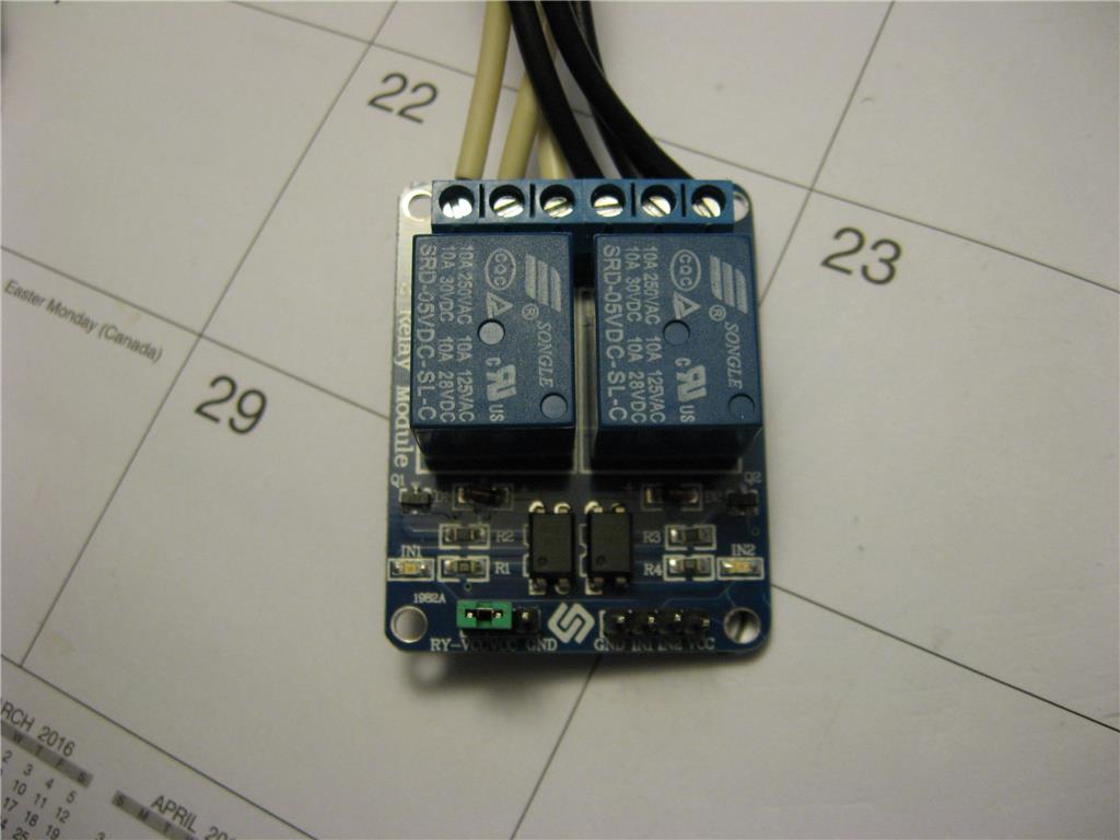
There has been much confusion on how to add a relay to an Ezb. There are three style relays, relay only, relay with a built in transistor circuit, and a relay with an opto-couple circuit. I have the relay with an opto-couple circuit. (817C) ?
This relay requires a 10 K resistor placed in series with the digital output. It is programmed by using a digital output, and "Set Digital". The issue is when the signal sent is "On" the relay is turned off. When the signal is sent "Off" the relay turns on.
This operation needs to be accounted for in your design so relay do not come on during a start up.

Ok, I hooked all back up with no resistor. I sent a signal Off, nothing happened except the led got brighter. I sent a On signal the led got dimmer, but the relay never activated.
I next inserted a 10k resistor in series with D0 to the In1 on the relay, and Off signal turned on the relay, On signal turned off the relay.
Just for info I am using an external power supply 5vdc @ 225 ma..
I saw it work on your video, but mine doesn't.
The gnd pin near the jumper is just a gnd.
Note: I also have a 8 relay board. I connected it as you did and it didn't work. I added the resistor and it works, but I still have the led issue.
I am at a loss? Insanity is taking over.... LOL....
@Andy are the external supply ground and ez-b ground connected somewhere?
5V, 225mA supply seems a bit weak, have any USB chargers that are 1A rated?
Yes with the common grounds. I will dig up a higher current 5 vdc power supply and test tomorrow. Thanks,
Andy,
Can you write the resistors values (numbers) r1, r2, r3, r4 ?
Do you mean a resistor color chart ?
10k is brown, black, orange and maybe a gold stripe on the last one. I used it in series with the signal.
no the pcb resistors
you wrote:
this means the relay works with a 10K resistor between EZB pin and IN1 ?
when you tried without the resistor did you connected both IN1 to D0 and IN2 to D1 ?
if not please connect both.
Good Morning,
I took the values off the boards (the 2 relay board and the 8 relay board are the same.) They are: r1=102 r2=115, r3-115 r4=102. The 8 relay board continue with the same values. The transistors looks like J3Y. The opto-coupling is a 817c B1419 on the 2 relay board and AFETEL 817C U448 on the 8 relay board.
I am currently running these boards using a tip 120 circuit, and they works fine. I prefer to eliminate the slave board and run direct. Even though it is inverse logic, I can rewire and reprogram them to work correctly. I will continue my test later this morning.