
Asked
— Edited
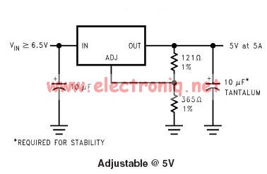
Usage Of Lm1084 Adj To Turn 7.5V Into 5V
So after a long struggle, I have still not been able to Make my lm1084 adj output 5v. Using this diagram has not worked, and in fact actually steps up the voltage.
Note that this voltage increase is without load. With the load of an electric motor, the output power drops to 4.75 and stays there no matter the resistance applied to the adjust.
I have tried 2 lm1084's but no luck. Any ideas?

I just use this image and solder my servo leads accordingly (directly to the contacts) ... I don't use any other components like resistors/capacitors etc.... I have the dedicated 5V version of the LM1084, however (not the variable one).
Have you tried putting pin 1 to ground?
Who you talking to @Mel? In Techno's diagram there is no pin reference.... and to me they all look like they are in one form or another already to ground....
It says "PIN 1 ADJ/GND" in the package diagram.
Why are you using the lm1084 adjust? Use the lm1084 that outputs +5 and you won't need to adjust. And use one LM1084 per motor with heat sinks... But this is not what i recommend
The issue you're experiencing is common - because of the type of regulator. It's a linear voltage regulator, which has a hard time normalizing voltage and amperage. This happens because the efficiency rating is quite low on a linear voltage regulator - check the data sheet. The data sheet is your bible for electrical components.
This is the reason the EZ-B v4 does not have a voltage regulator for the power pins. I generally ignore the question about putting voltage regulator on the ez-b because I've answered it so many times - but unless someone really digs into voltage regulators, they'll never understand the complexities of why an EZ-B will never, ever ever have voltage regulators on the power pins for servos or motors.
Firstly, a motor should never ever ever ever ever ever ever ever ever ever ever ever ever ever ever ever ever ever ever ever ever be powered by a voltage regulator. If you do, then the electrical design of your robot is wrong. period.
This statement is due to the fact that voltage regulators were never and will never be designed for motors - at least not in the traditional sense. There are "motor voltage regulators", but not in the form factor or component factor that you're familiar with for solid state. The LM1084 that you're using is for solid state, not motors. Keep reading...
You may find some old posts of mine regarding this topic - but specifically what is required knowledge is how a motor works - and how it differs from solid state components.
Without getting into the physics of how a motor differs from solid state in a current perspective - let's just review the physical operational differences of the two. First, you have an IC, second you have a Motor. When you look at them, with your eyes, you will see one is sparking and spinning at inconsistent speeds drawing inconsistent current generating inconsistent heat with magnets and gears and making a bunch of noise and electrical interference and getting hot - just inefficiently brute forcing electricity into another form of energy. Meanwhile, the IC is a little non-moving components with no sparks and may get a little warm but has quite a consistent datasheet defining it's operation.
Okay, so let's compare the datasheet information of an IC vs Motor. Try it, it is like comparing an Apple to a Light Bulb - there is no similarity to even begin a comparison between the two.
If the only similarity that you're going on is "they both use electricity", then you will have to realize the similarity between an Apple and a Light Bulb both consuming energy as well - so how can you compare an electric motor to an IC? You can't.
So - the big question is.... Historically, what do products use for voltage regulation in motors? I mean, your dvd player must have one. Heck, even your microwave rotates a plate, so it must have one?
Well - the answer to both of those questions is considerably different - but demonstrates the two approaches used to "regulator motor speed" within its operational voltage range.
Your dvd player - it has a motor but the speed of that motor is important. So, it doesn't connect directly to the battery. Instead, it runs through a motor controller (hbridge/mosfet). A motor controller is how you power a motor from a higher voltage without using a voltage regulator meant for solid state components - it's not just for controlling speed between 0-100%. The motor controller will accept PWM (pulse width modulation) to normalize the output speed. There are two approaches to do this, one is based on a small IC/micro monitoring the output shaft speed with a sensor. The other method monitors the amperage of the motor after the hbridge which adjusts the PWM accordingly. Obviously one provides more accuracy than the other - but they both produce similar results.
Your microwave - the question is, why doesn't your microwave plate rotate at 60hz? Because it is unregulated AC voltage after all. So 60hz would mean it's spinning 60 times a second. Well, the answer is simple - it uses gearing. The motor spins at the speed relative to the number of magnetic coils wound into the motor, which is most likely 1:1 for cost savings, so 60hz. And gearing slows the output shaft down to a speed which reheats your pizza evenly rather than splashing it on the walls. In this example, there is absolutely ZERO voltage regulation because the motor is powered directly off the power source.
Pick one of those two options - and power the motor's voltage within range of its datasheet.
So, as much as everyone thinks a voltage regulator is the solution to powering anything with an electric motor - it's also like thinking an ice cube makes a great hammer. Just because it's hard, doesn't mean it will hammer a nail. It's the wrong tool for the job.
If you wish to still move forward with using an incorrect power source for your electric motor application and band aid it with a voltage regulator, then I guess the only thing i can recommend is a non-adjustable LM1084. Use one per motor and get big heat sinks for it because they will get hot! If you're regulating solid state, use separate LM's for it as well. In fact, the solid state could use a more effecient regulator, such as the 5V Regulator MIC29300 +5V, 3A TO-220-3. This was used to power the solidstate on the EZ-B v3.1
Also, with energy efficiency in mind, why would you want to convert so much energy to heat when it could be used to power your motors? Get a proper battery power source and use voltage regulators for solid state components only.
Bookmark my reply - because i don't discuss this topic often
@Mel.... That's my diagram and I already know how to make them... I have made 10 or so 5v LM1084s and they all work great... @Techno is the one struggling because he is using the variable voltage LM1084s not the dedicated 5v version....
I mistakenly purchased adjustable versions, so that's the first problem.
Second, I discovered I messed up the pins, and had my wiring all bad. Its a wonder it turns on.
And to clarify, I don't intend to use it for a motor. I intend to use it to power relays. The motor is just a temporary test method until I get the relay wired up.
Thanks for the insightful info @DJ. I never realized the "nature of the beast". Now I'm just working to make it output 5v with resistors.