Asked — Edited
Resolved Resolved by irobot58!

Turning Off A Asabertooth

Hi gang,

I've been struggling and making slow progress with my rewiring of the DC motors in my B9. I decided to replace all my Pololu H-Bridges with a Sabertooth / Kangaroo combo. The Pololu H-Bridges were very good and did the job but I thought the Sabertooth / Kangaroo combo would make for a simpler setup with easier coding and better performance. well, that's all still to be seen. The coding is easier once you get to understand the serial commands and being able to use the servo controls and scripts in ARC is awesome. However the setup really wasn't that much simpler. I'm still having some issues with error codes at startup that stops any signal input. I'm working with Dimension Engineering to resolve this. I think it may be the potentiometer I'm using. Also I needed to add a battery for some place for the Sabertooth to dump the regenerative power, diodes to keep from back feeding the power supply from the regenerative power and I still need some way to shut off the new boards.

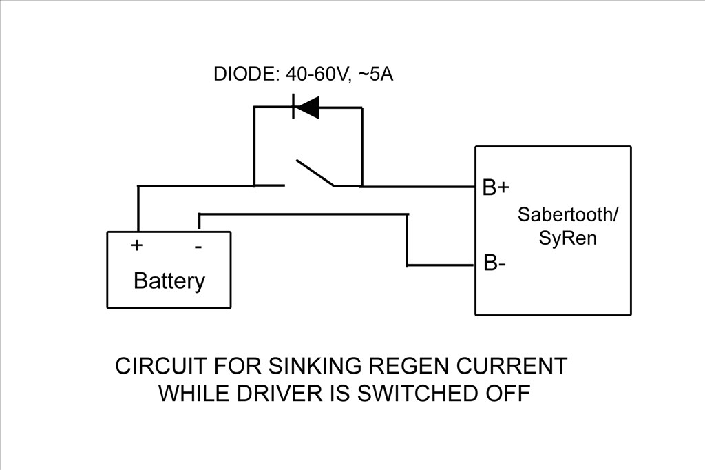
This brings me to my question; How are those of you using the Sabertooth turning off your controller? The battery keeps the board energized and you cant disconnect it because if done the Sabertooth has no place to dump the regenerative power. If the motor is moved by hand the Sabertooth can damage itself if it cant put the regenerative power back into the battery. I can think of a few ways and all will need a switch of some kind and a blocking diode. Something like this:

User-inserted image

I'm powering the boards from a 24vdc switching power supply with a 24vdc battery paralleled between it and the boards for the regenerative power to be dumped into.

Different ways to switch I can think of are:

1). A manual switch with a diode across it. This wont work as I don't want to mess with a different off switch for my DC current and my B9 is powered from wall AC current through converters.

2). A low side TIP122 switching circuit operated from EZB and startup scripts from ARC. The Sabertooth is self powered from the 24v power input that supply's the motor voltage. If done like this I'd need to totally isolate all neutral and common grounds going to the Sabertooth / Kangaroo boards and open them at the TIP122 switch. If I try to switch the neutral at just the Sabertooth power input point I still have a neutral feed on the other side through the Kangaroo X2 Where the EZB signal input is attached.

3). A high side switching circuit. I could build one and just switch the hot lead feeding the power input of the Sabertooth and this would turn off both boards. I'd need to use Power MOSFET as the TIP122 may not handle the amperage max I'd be pulling. The TIP122 is only rated for 5 amps and I may pull more then that at times. The Power MOSFET would be able to handle that load. I'm still trying to understand this high side switching circuit. I'm not really sure if I will only need one MOSFET in the circuit or if I need a pre-driver to drive the MOSFET. I've seen drawing of it donn both ways:

User-inserted image

User-inserted image

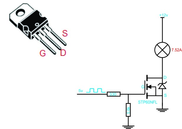
Still not sure which is the proper circuit to use and if I use the pre driver one what values to use. I still need more research to find out. Any recommendations? I'd love to find a High side switch that EZB could control. I did find one at SparkFun but it controlled 4 lines, was a shield type board and cost $60.

4). I could switch the high side with a relay triggered with a Low Side Tip122 switching. This seems redundant and I don't like the long term problems that may arise using a relay. Manly that the contacts on a relay may pit and fail and the relay would be energized all the while the robot is powered up.

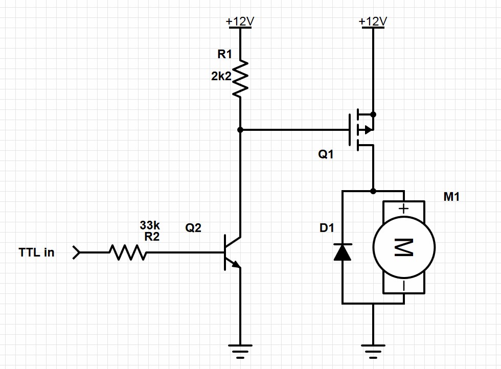
EDIT: Here's the final circuit that works nicely. I've placed diodes in circuit to both let the Sabertooth dump regenerative power back into the battery and also to keep the Sabertooth from back feeding the power supply. Without these diodes the Sabertooth and power supply would stay powered up from the battery after the robot was turned off. Also if the Sabertooth stayed powered after system shutdown the Kangaroo X2 would return errors and not run when the robot was started up again. Seems that if I shutdown near a limit switch and let the Sabertooth/Kangaroo slowly drain the power out of the battery till it was dead these errors would happen. It was very frustrating. Now when the EZB disconnects from ARC this switching circuit will open and shut down the Sabertooth/Kangaroo and the diodes will act as described above. Here's my circiut:

User-inserted image

I used the resisters listed. With the following Power MOSFET driver and Transistor pre-driver I'm good up to 55v and 19 amps: Q1 MOSFET driver: IRF9Z34NPBF Q2 Transistor pre-drive: 2N3904 Sub the Motor in the drawing for the Sabertooth.

Anyway, sorry for the long post. I'd welcome any thoughts or ideas.

Thanks, Dave


ARC Pro

Upgrade to ARC Pro

ARC Pro is your passport to a world of endless possibilities in robot programming, waiting for you to explore.

#1  

Hey Dave! The sabertooth looks like an awesome board and one day I too may have such a controller as my robot is getting heavy!(wood) Doing a bit of research from the spec sheet for my own curiosity and possibly to help you out. On page 19 the last page is an emergency stop feature it describes tieing all the S2 together and pulling them LOW shutting off the driver! Perhaps that would be a very easy solution! Best of Bot(luck) , Glen

#2  

Thanks for the pointer Glen. I'll ask DE if this can be done. I'm useing the Kangaroo X2 and one of it's connector lugs attaches into S2. I'm not sure if S2 on the Kangaroo can be used the same way. Everything I've read says S2 on the Kangaroo is the RX output the way I have it set up. You can see it in the pic below. S2 is the connection point to the far right:

User-inserted image

#3  

There must be a serial command to power down the Sabertooth! S2 as you pointed out is being used by the Kangaroo!

#4  

There is a power down command but the board stays active. They say:

"This command will turn off the motor and control system. You can still read position and speed with the motor powered off. This is used to allow the system to freewheel or to save power. " I;ve used this command and it really does nothing for me the way I'm useing the board.

I asked DE last week about the best way to power down the boards and they sent me the first drawing I posted above.

#5  

It doesn't make sense to me to be able to power down the board , yet still be able to read position and speed.?! The first diagram with the switch and diode is the simplest which shuts off the boards while dumping any extra regen back into the battery( while pushing the disconnected robot around ). and the circuits that give TTL logic (which is what you would like, ie "B9 shut down motors" but don't give values for components. I hope some users of the Sabertooth chime in!.....I suspect they just power every thing down with out knowledge or concern of regen energy....

#6  

Hi all,

I'm making some progress on my issue. I'm still having problems with control signals not being accepted at start up. However I'm making progress. I've gone from complete lock up with 3 continuous blinking LED lights on the Kangaroo X2 to the board acting like it's accepting signals but nothing moving. I have to power cycle the Kangaroo/Sabertooth boards again after power up and everything works great. I'm working with Demention enegeneering trying to resolve this. So far what has helped was to change my potentiometer from 50k down to 10k and fixing a couple loose connections. The issue only happens when I start up near a limit switch. DE seems to think part of the problem may be the way I power down. Which brings me to my next issue and the one I started this thread about.

As mentioned I want to find a good way to remotely power up the Sabertooth with the EZB and disconnect from the dump battery when the robot is powered down. I really think the best way (in my set up anyway) is disconnect the power feed to Sabertooth on the high side (positive lead). After doing a lot of research and work on a solderless breadboard I found that the 3rd drawing I posted above is the circuit I need to use. With the proper parts in the circuit it works great! I'm able to switch the boards on and off using the positive high side lead from EZB.

EDIT: Here's the final circuit that works nicely (I've replaced the old non working circuit I had posted). I've placed diodes in circuit to both let the Sabertooth dump regenerative power back into the battery and also to keep the Sabertooth from back feeding the power supply. Without these diodes the Sabertooth/Kangaroo and power supply would stay powered up from the battery after the robot was turned off. Also if the Sabertooth/Kangaroo stayed powered after system shutdown the Kangaroo X2 would return errors and not run when the robot was started up again. Seems that if I shutdown near a limit switch and let the Sabertooth/Kangaroo slowly drain the power out of the battery till it was dead these errors would happen. It was very frustrating. Now when the EZB disconnects from ARC this switching circuit will open and shut down the Sabertooth/Kangaroo and the diodes will act as described above. Here's my circiut:

User-inserted image

I used the resisters listed. With the following Power MOSFET driver and Transistor pre-driver I'm good up to 55v and 19 amps: Q1 MOSFET driver: IRF9Z34NPBF Q2 Transistor pre-drive: 2N3904 Sub the Motor in the drawing for the Sabertooth.

I'm not sure if it was necessary or I'm just anal but I bumped the pre driver up to a TIP122. I'm just a little worried about the regenerative power coming back from the Sabertooth and back feeding the circuit. I thought the smaller 2N3904 might be a weak link guarding between the EZB and 24v power supply. Anyway, I could be wrong but a bigger transistor couldn't hurt. I also added a couple blocking diodes (not shown) to help block the Sabertooth's regenerative power from back feeding this circuit. I couldn't figure out how to keep backfeed completely out of the circuit but at least I'm back feeding it from the front end and not the back end.

Next thing will be actually building the board and installing it. Perhaps after being able to turn off this board at power down and then power it back up with the EZB after the robot is active will solve my control problem. I'll keep ya all posted. :)

#7  

Glad to hear things are working out! :D I guess the ultimate way of isolating dangerous back feeds etc is with an opto isolater. Your provided circuit is very useful for everyone! Going forward........

#8  

Hey Glen, when I get the circuit finalized I'm going to try to learn how to use that circuit designing web site Rich and others have mentioned. I'll try to draw up a decent schematic of how this circuit is built. I think this high side switch circuit along with the low side switching circuit that can be controlled by EZB are something that all robot builders would find handy.

United Kingdom
#9  

Dave, I am part way through making tutorials for Express PCB and Circuits.io which should help you, I'll be doing some more on them this weekend :)

Glad to see you're making progress, to be honest I've not really read the posts as I've been very busy lately but it seems you're getting there so it's all good. After a very quick scan over, and you may have thought of this, you may have posted it and I missed it but couldn't you use some relays along with some transistor/mosfet switching circuits to cut power, redirect power etc.? The Transistor/Fet could be controlled via a digital output on the EZ-B.

I have really been trying to find the time to read this topic, maybe I'll finally get around to it later tonight.

#10  

Rich, thanks for caring. It's nice to know you're willing to help out a guy even as busy as you are.

I know you haven't read this thread yet but I did mention once thst relays would be the easiest way to go. I could switch it with EZB from the low side. However in this application I want to avoid using a relay because I don't want to put up with possible relay contact failure from pitting. Also they are slow and noisy. An electronically switched circuit is very elegant, quiet, and quick. Plus it was a challenge for me and something I had never done. It is making me feel good that I'm able to overcome my ignorance to make this work. Isn't that what life is all about anyway?

EZB will be doing the switching of this high side switching circuit.

I look forward to your tutorials. Well I'm sure they are going to help me a whole bunch. Graph

Thanks again!

#11  

WOW Dave! I nearly fell out of my robot building chair when I looked at my emails and saw that I had successfully answered your question! My modesty tells me that you really solved it and had the answer very quickly and should take credit for that:) . I am flattered that you chose me to receive the ribbon! That's my very first one!:D It has been one of my goals to try to assist people when I can and return some of the "ginormous" support (as the young kids say) from the community. I know Rich is a pillar on this Forum who solves 80 percent if not more and for that matter you yourself I consider in the same category. Thanks once again! and all the best.. :D

#12  

Glenn, you deserve the credit on this 1. Your moral support help me hang in there 2 find the answer more then you know. Thanks for your support. Having Rich pop in also a huge help. It's good to know that's we're not alone in this.

#13  

Ahh, success! I've built the EZB controlled high side switching board on a Radio Shack prototype circuit board and installed it into B9. It works great! I also now don't get any error blinks from the Kangaroo X2 on start up and it will accept commands without a power cycle! I think the problem in my setup is I needed to have the EZB and the robot power up first and then have EZB turn on the Sabertooth/Kangaroo boards. I don't entirely understand why this is so. It may be that the Kangaroo X2 tries to stop a motor when it thinks it's running away. When I power up all at once near a limit switch it may think it's out of control and shuts down. However that's just a guess.

I'll try to post pic and a vid and more details soon.

#14  

I have one thing to say ....... SWEEEEET:D umm two things looking forward to the vid and pics

#15  

Thanks for working this out. I didn't even know it was a concern, and probably would have ruined my Sabertooth when I get K-1900 built by pushing it around un-powered.

Alan

#16  

No problem Alen . I'm not sure how risky it really is to not have a place for the regen power to go if disconnected from the battery. The manual says you "may" damage the Sabertooth if you move the motor when disconnected and place to dump the regen power. I didn't want to take the chance by not following directions. ;)

Here's some pics of the process of building the High Side switching circuit. I'll be updating the schematic above showing the proper placement of the extra diodes when I can :

Laid out on the breadboard: User-inserted image

The final built circuit: User-inserted image

Two of the three diodes are to channel the regeneration power from the Sabertooth past the circuit and off to the battery. The third is for kickback voltage (if any) from the load. I'll be updating the schematic above showing the proper placement of the extra diodes when I can. It's all a very tight fit but I wanted to keep things small. Notice the resistor across the front of the Mosfet? User-inserted image

User-inserted image

User-inserted image

Installed in B9 and controlled by EZB. Works great! Notice all the cables attached to the Kangaroo (located just behind the EZB and attached to the Sabertooth). Those are reading two potentiometers and four limit switches. It's taking a lot of load off the EZB. User-inserted image

Next I need to work on getting the speed ramping working.

#17  

Here's the final circuit drawing that works nicely. I've placed diodes in circuit to both let the Sabertooth dump regenerative power back into the battery and also to keep the Sabertooth from back feeding the power supply. Without these diodes the Sabertooth and power supply would stay powered up from the battery after the robot was turned off. Also if the Sabertooth/Kangaroo stayed powered after system shutdown the Kangaroo X2 would return errors and not run when the robot was started up again. Seems that if I shutdown near a limit switch and let the Sabertooth/Kangaroo slowly drain the power out of the battery till it was dead these errors would happen. It was very frustrating. Now when the EZB disconnects from ARC this switching circuit will open and shut down the Sabertooth/Kangaroo and the diodes will act as described above. Here's my circiut:

User-inserted image

I used the resisters listed. With the following Power MOSFET driver and Transistor pre-driver I'm good up to 55v and 19 amps: Q1 MOSFET driver: IRF9Z34NPBF Q2 Transistor pre-drive: 2N3904 Sub the Motor in the drawing for the Sabertooth/Kangaroo combo.

I also went back above in the past posts and added this info and took out the non working circuits.

Hope this helps others wanting to control their robots with a EZB controlled Sabertooth/Kangaroo combo. Have Fun!

#18  

Hey Dave... I exclusively use sabertooths for all my robotics.... Granted, I really haven't read up on the kangaroo... what is it used for and why would I need it? I have no issues powering my sabertooth with my ezbs... I just use a regular toggle switch to switch on/off the sabertooth( powered straight from the battery)... I am probably missing something but my simple set up works fabulous with my ezb.... I exclusively use scripts and serial commands to control my sabertooths... I did check power consumption on an idle 2x5 sabertooth (I would assume the 2x10 would be similar)... about 15mA....

#19  

The Kangaroo x2 is a daughter board made by the same company that makes Sabertooth that can turn your DC motor into a servo. It plugs into the control side of the Sabertooth. It's takes all the load off the EZB for position and speed control by sending serial commands through only one of EZB's digital ports. Hopefully when the V4 EZB arrives with it's many Uart port I'll be able to get speed and position feedback from the Kangaroo for better control.

As mentioned in the above posts I was having problems when the Sabertooth would drain the battery after power down if it shut down near a limit switch. Then on power up I was getting error codes from the Kangaroo that would lock the controller down. If I shut the system down when the robot was in the center between the limit switches I would not have this issue. I had to find a way to turn off the Sabertooth/kangaroo combo at system shutdown and keep them from being kept alive by the battery till it slowly died.

Also I don't want to flip an extra manual switch to do this so I built this circuit that will let EZB do it through simple scripts and one digital port. When the EZB disconnects the Sabertooth/Kangaroo goes dead.

Hope that makes sense.

#20  

Totally makes sense.... I might grab me a kangaroo board now... thanks for the explanation... :)

#21  

Hi Dave I was just fixing to buy the components for your circuit and realized you are using 24 vdc. My motors are 12vdc powered only by the two 12v batteries I have in parallel, would this change anything? (Running the sabertooth 5x25 with or without Kangaroo) Matt

#22  

@mdeming1, You should be OK with everything. The only think I'm not sure about is R2. I suggest you set it up on a breadboard like I did and see if it works. If not cut the value of R2 in half. You could go through all the math and stuff to figure it out exactly but it's not like we're building the Space Shuttle here. ;)

#23  

@Dave Shulpius Sometimes it feels like I am! Besides, your robot, by the LIP timeline, falls in space shuttle time-frame and it looks at least as advanced as some of the nasa stuff! Just a few questions:

1)Didn't I see a thread you posted regarding the kangaroo where you added a ground wire on the kangaroo or something like that to emulate two way communication? I've been reading so many threads I could be mixing them up.

2)I bounced the circuit idea for my setup off of a friend that is more versed in circuits and electronics than I am. He wasn't as sure about it and thought I'd have to put mine in series which would then cause issues with the motors I have. I'm not sure he really understood the goal and the motor regeneration current from the sabertooth though.

2a)Just to be clear. Is your robot powered entirely by the batteries? Mine is using 12v motors and 12v batteries in parallel with everything powered through the sabertooth.

I bought all of the components I didn't have at Radio Shack yesterday except for the mosfet which I have to get from amazon. I decided to pick up two additional ultrasonic sensors while I was there as well. I couldn't figure why my bill was so high. Turns out they are charging $30 a piece for their U.S., I'll be returning them and getting the EZ Robot ones thank you very much!

Thanks again for all of your help. Matt

#24  

Hi Matt,

I'm powering my robot completely with a 24vdc power supply. I have the 24v battery installed so the Sabertooth regeneration will dump the power into the battery and not into the power supply where it will trip it's internal breaker. If you're running off of batteries you really don't need the last complicated circuit I posted. I'd suggest building this circuit:

User-inserted image

You can control the on/off switch with EZB using a simple TIP transistor circuit:

User-inserted image

Rich has a nice tutorial on how to build one here:

TIP Circuit

Good luck and let me know how you preceded.

#25  

Don't build anything off my last post. Its a little confusing and incomplete. Rich's sketch is for a low side switch. I show a high side switch. We also need to consider how many amps you may draw. A TIP may not be able to handle your load. That's why I used a MOSFET with a per-driver. This is what happens with only three hours sleep and an adult beverage in you. blush

#26  

HI Dave I totally understand the sleep and beverage situations!

I think i'll continue trying to sort out the programming issues first. I got my magnetic encoders yesterday so that is a start, now to see if I can get that kroo to read them.

#27  

My last sketch of the high side switch should work nicely for you with the parts I listed. You would just have to remove the Power Converter part the the diode blocking back to it. However I'm just not sure you need to get that complex.

Keep us posted on the progress your making. @Toymake is doing some great work with his Roo / Sabertooth combo and has offered to share his excelent ramping script when he gets his V4.

Did you ever get your V4 yet? You'll need it's two way serial feature if you do any advanced controlling with the simple commands.

#28  

Negative on the V4, I only ordered it a week or so ago but I did get an email saying it had moved to the next step in processing. So am I imagining the post where you added a ground underneath the board for two way with the kangaroo? Also, I was looking at this in the kangaroo manual yesterday:

Enable multi-Kangaroo mode (shared signal lines) When disabled, Kangaroo drives the S2 line high when it is not sending data on it, to give a stronger idle signal. One consequence is that S2 cannot be shared.

When enabled, Kangaroo will only drive S2 when it is sending data, and will enable an internal pullup resistor when it is idle. The idle signal is weaker, but S2 can be daisy-chained between them.

would this function solve the two way com problem with the v3 board?

#29  

Just some various information that may be helpful:

Three blinks on the Kangaroo x2 is Control Error.

If a motor is powered off and Kangaroo x2 is trying to move, it won't be able to move, so it will think something is obstructing movement and continue to increase the commanded motor power. Once it's at 100% motor power for a certain amount of time and seeing no motion, it will assume it is stuck and throw a Control Error. Technically you can move a pot or transmitter back/forth/back/forth/back/forth (I believe it's three times) to reset this, or with serial reissue a start command.

In DEScribe, this setting is located in Control -> Advanced -> Safety -> Enable runaway detection.

This is for safety because this case (motor powered off, commanding 100% power, no motion meaning no feedback ticks), from the Kangaroo's perspective, is identical to the motor powered on, commanding 100% power, feedback wire has been cut case. That's a dangerous one.

For what it's worth, Kangaroo, when a power down command has been issued, won't throw a Control Error because the control system isn't running in that case.

On Sabertooth 2x32 only, Voltage Clamp feature on P1 and P2 can dump the power to a resistor bank.

#30  

Dave, on the Sunshine robot, I really haven't paid attention. But, on the LEAF robot no matter what I did, it would still have a little flashing blue light. It was aggravating. But, I just left it like it was. That is one reason I sort of shyed away from buying another sabertooth. So, I have experienced this as well.

#31  

Mel, who are you responding to? Does Dave mention anything about a flashing blue light?... Was not the last post (by James) talking about the flashing leds (representing error codes) on the Kangaroo board (and not the sabertooth...)? So it was the flashing blue light on the sabertooth that put you off of the sabertooth initially? Are we talking about the one you just bought or a previous sabertooth you once had? Don't you think that is rather trivial reason? Are you sure it wasn't because you were having difficulty in getting it to work.....? Anyway, if you don't like the blue light, just cover it with a piece of tape....

#32  

Thanks very much @James for the excellent explanation. That's would make perfect sense.

The power down command kinda puzzles me. It seems to do the same as the start up command. When ever I issue a command to move the motor and after that movement is complete, the motor will stay engaged and locked in that position. If I try to move the motor it will fight me to stay in that spot. I have to issue either a Start or Powerdown command to put it in a rest state.

@Mel, I don't think there is a blue led on the Sabertooth. I think it has several leds but change from red to green and and maybe even orange. I'm going from memory so I may be wrong.

#33  

Dave, you are right... I get a green when just powered up... I am sure I remember red as well... There is however an error LED on the 2 x 12 sabertooth... I have no idea what colour it is (probably in the manual, though) as I have never seen it light up...

#34  

Well, if you know anything about me you know I was able to get that little error led to light . I had the dip set to watch a battery but was supplying it with a power supply. It started blinking red really fast. eek :)

#35  

Dave,

Power Down will stop trying to control position/speed and instead tell the Sabertooth to use 0% motor power.

Start does everything Power Down does, and also clears error conditions and (when using quadrature encoders) resets the ticks so the current position is the 0 (or the machine zero, if you've set one). This last bit is because a control error can be caused by a disconnected or swamped feedback line.

For the motor fighting you, is holding position afterwards undesirable for your application? The normal behavior is fairly servo-like but also for plays well with a robot on a hill slope.

James

#36  

@James, thanks so much for the advice and visiting our fourm. You seem very knowledgeable about these fine boards. Are you with DE? If so we're very fortunate to have you here. We have been discussing both the kangaroo and the Sabertooth a lot here these past few months. I'm sure if we can get one of our bots here to use them successfully with code examples and forum support I'm sure more people will use them. I'm using two Sabertooth 2x12 in my full size Lost in Space B9 and each has a Kangaroo. I really like them and how they work. My only real complaint is the lack of speed ramping when set in position mode and using Simple Serial. I was told by DE support that this feature may be available by this fall.

Anyway, thanks again for the explanation of the commands. That's exactly what I needed to know. The reason I need to send a Start command after each position move is because the motors humm and sometimes rock back and forth when the move is over. This stops when I send either of these two commands.

#37  

@Dave, yes, Kangaroo's my baby. :)

You might try upping the Position Deadband in DEScribe's Control tab if you are getting rattle when idle. With quadrature feedback, that's usually caused by cogging in the motor: some motors will stick at low speed, so if Kangaroo is off by a tick or two, the power needed to unstick the motor is also enough power to push it far past.

Slightly upping Position Deadband can make that disappear (for most systems it doesn't take much). By default, Kangaroo tries to (and on many systems can and does) get within 1 quadrature tick in Independent mode and 2 quadrature ticks in Mixed mode.

Position mode ramping is definitely on the agenda. If you find any other features that would be useful, oversights in documentation, etc. any kind of feedback I'm all ears.

James

#38  

@James, this is awesome info that I really needed. Thanks so much. It's great to have you here and willing to advise.

I do have a couple other thoughts about the kangaroo but they're mostly about support. While these are awesome control boards I think the user and setup manual could be a little more user friendly for the less advanced users. Mainly the use of the DESCRIBE software and a simpler to understand explanation of each section and what is and isn't effected in each mode.

Also a user forum like we have here where other users can help each other would be great.

Thanks again for the help and listening. I can't wait to get the ramping feature you mentioned!

#39  

well did the ramping feature ever get included, Dave do you have code for it? Also connecting cables for the Kangaroo shoul be offered with them or at least suggested to buy. After teach mode wouldnt work in RC mode support said to use DEscibe then I found out I needed a cable soi had to wait for mailwhen I should have already had it confused

#40  

Hi Reed,

A few years ago I talked directly to dimension engineering and requested that they look into adding the ramping feature into the position feature of the Kangaroo. Up till then the only way to get ramping effect was with the Velocity setting. They said that they already had a bata program that their engineers were using that has a ramping feature. hey actually called it Acceleration control. They sent me a copy and it worked wonderfully. I'm not sure but I think they have started including it in the latest firmware versions. I haven't upgraded because it works for me as is. I fully advice that you learn the DEscibe software as it's the best way to set up your Kangaroo. I prefer running the auto tune directly from inside DEscibe. You can better visually see what is happening and better set up the way it tunes.

As far as ARC and your B9, I understand being overwhelmed. Once you start playing around with ARC and start making things move it will all start to come together. I suggest that you download other people's projects and script examples and see how the scripts are written, structured and can interact with each other. In ARC go to the top menu bar and under the File tab find the EZ Cloud App Store section, then click on Open. That will take you to a page where you can search and download a ton of examples. On the right side of the screen is where you can search many kinds of ways. I have one of my older B9 projects in there with most of my working scripts. Sadly my project got way to large to save in their cloud service and I can't save there anymore. I'll send it to you privately in a different email. It probably has everything you'll need as far as scripting for your B9 but be warned, It's very disorganized and rambling. I have many scripts that start and run other scripts or are dependent on one or two other scripts. They are sometimes they are hard to follow. I've tried to add directions in each script as to what each does but sometime I've changed the scripts and not updated the notes. I get to excited and move on. It won't work to control your B9 but it will give you an idea how I control mine.

I also suggest that you read as many lessons and watch all the videos you can on the EZ Robot website. They even have video lessons now. I know it seems like most are geared towards their robot but they will really help you understand the entire platform and how it works. A few hours of studying these will really payoff when you start trying to control your robot with ARC. Also don't hesitate to ask questions on this forum. The guys usually are very helpful.

OK, not that the business is done I wish you luck and much fun. It's really thrilling when your robot starts moving around. Let me know if you need some help with the Roo. It can be a bugger until you get a successful tune. One suggestion, you need to have everything in the motor circuit correct and connected properly, dip switches set right and with the right power supplied or it wont start. It needs a feedback device with a doubt or no go. A simple pot will work but a encoder built onto the of a motor really shines. I like the Servocity gear motors with the encoders already mounted. That's what I'm using on my radar and it works like a charm.

Let me know if you need anything and have fun! Dave