Hi gang,
I've been struggling and making slow progress with my rewiring of the DC motors in my B9. I decided to replace all my Pololu H-Bridges with a Sabertooth / Kangaroo combo. The Pololu H-Bridges were very good and did the job but I thought the Sabertooth / Kangaroo combo would make for a simpler setup with easier coding and better performance. well, that's all still to be seen. The coding is easier once you get to understand the serial commands and being able to use the servo controls and scripts in ARC is awesome. However the setup really wasn't that much simpler. I'm still having some issues with error codes at startup that stops any signal input. I'm working with Dimension Engineering to resolve this. I think it may be the potentiometer I'm using. Also I needed to add a battery for some place for the Sabertooth to dump the regenerative power, diodes to keep from back feeding the power supply from the regenerative power and I still need some way to shut off the new boards.
This brings me to my question; How are those of you using the Sabertooth turning off your controller? The battery keeps the board energized and you cant disconnect it because if done the Sabertooth has no place to dump the regenerative power. If the motor is moved by hand the Sabertooth can damage itself if it cant put the regenerative power back into the battery. I can think of a few ways and all will need a switch of some kind and a blocking diode. Something like this:
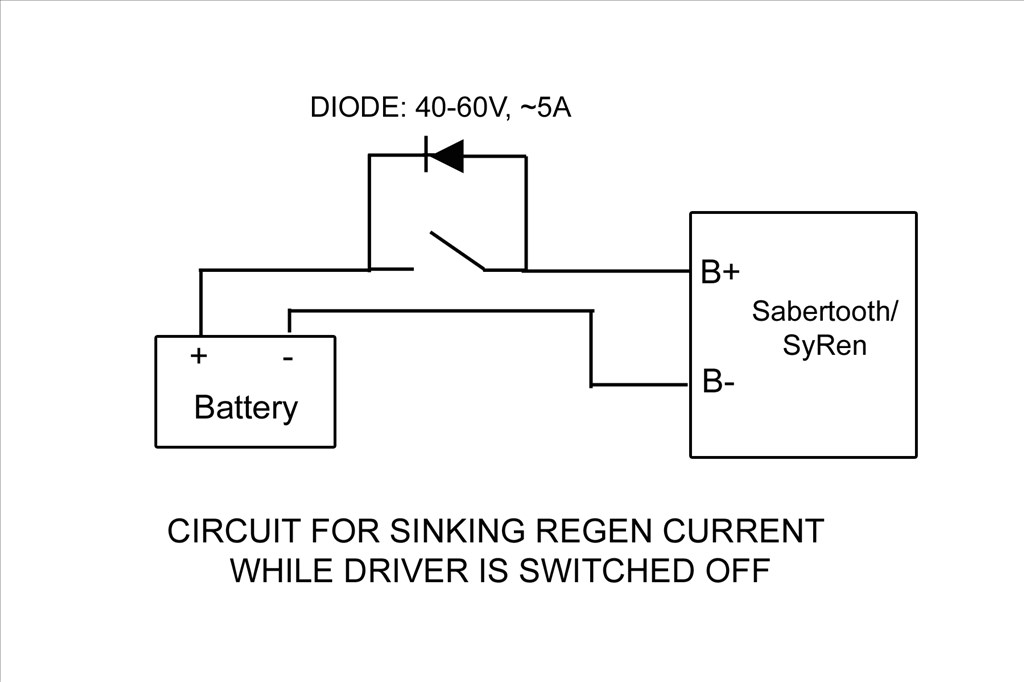
I'm powering the boards from a 24vdc switching power supply with a 24vdc battery paralleled between it and the boards for the regenerative power to be dumped into.
Different ways to switch I can think of are:
1). A manual switch with a diode across it. This wont work as I don't want to mess with a different off switch for my DC current and my B9 is powered from wall AC current through converters.
2). A low side TIP122 switching circuit operated from EZB and startup scripts from ARC. The Sabertooth is self powered from the 24v power input that supply's the motor voltage. If done like this I'd need to totally isolate all neutral and common grounds going to the Sabertooth / Kangaroo boards and open them at the TIP122 switch. If I try to switch the neutral at just the Sabertooth power input point I still have a neutral feed on the other side through the Kangaroo X2 Where the EZB signal input is attached.
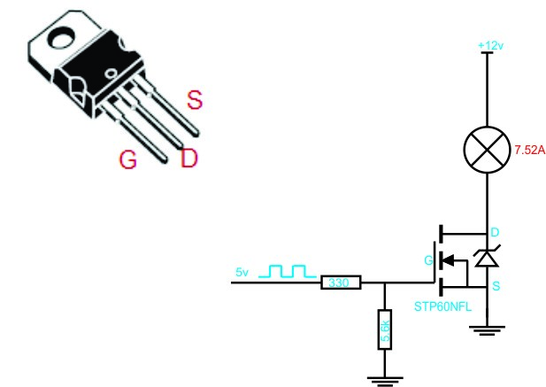
3). A high side switching circuit. I could build one and just switch the hot lead feeding the power input of the Sabertooth and this would turn off both boards. I'd need to use Power MOSFET as the TIP122 may not handle the amperage max I'd be pulling. The TIP122 is only rated for 5 amps and I may pull more then that at times. The Power MOSFET would be able to handle that load. I'm still trying to understand this high side switching circuit. I'm not really sure if I will only need one MOSFET in the circuit or if I need a pre-driver to drive the MOSFET. I've seen drawing of it donn both ways:
Still not sure which is the proper circuit to use and if I use the pre driver one what values to use. I still need more research to find out. Any recommendations? I'd love to find a High side switch that EZB could control. I did find one at SparkFun but it controlled 4 lines, was a shield type board and cost $60.
4). I could switch the high side with a relay triggered with a Low Side Tip122 switching. This seems redundant and I don't like the long term problems that may arise using a relay. Manly that the contacts on a relay may pit and fail and the relay would be energized all the while the robot is powered up.
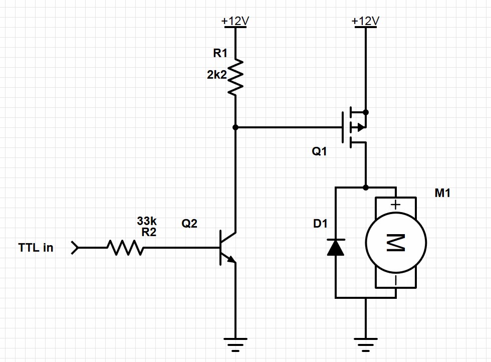
EDIT: Here's the final circuit that works nicely. I've placed diodes in circuit to both let the Sabertooth dump regenerative power back into the battery and also to keep the Sabertooth from back feeding the power supply. Without these diodes the Sabertooth and power supply would stay powered up from the battery after the robot was turned off. Also if the Sabertooth stayed powered after system shutdown the Kangaroo X2 would return errors and not run when the robot was started up again. Seems that if I shutdown near a limit switch and let the Sabertooth/Kangaroo slowly drain the power out of the battery till it was dead these errors would happen. It was very frustrating. Now when the EZB disconnects from ARC this switching circuit will open and shut down the Sabertooth/Kangaroo and the diodes will act as described above. Here's my circiut:
-635323067643352500.png)
I used the resisters listed. With the following Power MOSFET driver and Transistor pre-driver I'm good up to 55v and 19 amps: Q1 MOSFET driver: IRF9Z34NPBF Q2 Transistor pre-drive: 2N3904 Sub the Motor in the drawing for the Sabertooth.
Anyway, sorry for the long post. I'd welcome any thoughts or ideas.
Thanks, Dave

Dave, I am part way through making tutorials for Express PCB and Circuits.io which should help you, I'll be doing some more on them this weekend
Glad to see you're making progress, to be honest I've not really read the posts as I've been very busy lately but it seems you're getting there so it's all good. After a very quick scan over, and you may have thought of this, you may have posted it and I missed it but couldn't you use some relays along with some transistor/mosfet switching circuits to cut power, redirect power etc.? The Transistor/Fet could be controlled via a digital output on the EZ-B.
I have really been trying to find the time to read this topic, maybe I'll finally get around to it later tonight.
Rich, thanks for caring. It's nice to know you're willing to help out a guy even as busy as you are.
I know you haven't read this thread yet but I did mention once thst relays would be the easiest way to go. I could switch it with EZB from the low side. However in this application I want to avoid using a relay because I don't want to put up with possible relay contact failure from pitting. Also they are slow and noisy. An electronically switched circuit is very elegant, quiet, and quick. Plus it was a challenge for me and something I had never done. It is making me feel good that I'm able to overcome my ignorance to make this work. Isn't that what life is all about anyway?
EZB will be doing the switching of this high side switching circuit.
I look forward to your tutorials. Well I'm sure they are going to help me a whole bunch. Graph
Thanks again!
WOW Dave! I nearly fell out of my robot building chair when I looked at my emails and saw that I had successfully answered your question! My modesty tells me that you really solved it and had the answer very quickly and should take credit for that . I am flattered that you chose me to receive the ribbon! That's my very first one!
 It has been one of my goals to try to assist people when I can and return some of the "ginormous" support (as the young kids say) from the community. I know Rich is a pillar on this Forum who solves 80 percent if not more and for that matter you yourself I consider in the same category. Thanks once again! and all the best..
Glenn, you deserve the credit on this 1. Your moral support help me hang in there 2 find the answer more then you know. Thanks for your support. Having Rich pop in also a huge help. It's good to know that's we're not alone in this.
Ahh, success! I've built the EZB controlled high side switching board on a Radio Shack prototype circuit board and installed it into B9. It works great! I also now don't get any error blinks from the Kangaroo X2 on start up and it will accept commands without a power cycle! I think the problem in my setup is I needed to have the EZB and the robot power up first and then have EZB turn on the Sabertooth/Kangaroo boards. I don't entirely understand why this is so. It may be that the Kangaroo X2 tries to stop a motor when it thinks it's running away. When I power up all at once near a limit switch it may think it's out of control and shuts down. However that's just a guess.
I'll try to post pic and a vid and more details soon.
I have one thing to say ....... SWEEEEET umm two things looking forward to the vid and pics
Thanks for working this out. I didn't even know it was a concern, and probably would have ruined my Sabertooth when I get K-1900 built by pushing it around un-powered.
Alan
No problem Alen . I'm not sure how risky it really is to not have a place for the regen power to go if disconnected from the battery. The manual says you "may" damage the Sabertooth if you move the motor when disconnected and place to dump the regen power. I didn't want to take the chance by not following directions.
Here's some pics of the process of building the High Side switching circuit. I'll be updating the schematic above showing the proper placement of the extra diodes when I can :
Laid out on the breadboard:
The final built circuit:
Two of the three diodes are to channel the regeneration power from the Sabertooth past the circuit and off to the battery. The third is for kickback voltage (if any) from the load. I'll be updating the schematic above showing the proper placement of the extra diodes when I can. It's all a very tight fit but I wanted to keep things small. Notice the resistor across the front of the Mosfet?
Installed in B9 and controlled by EZB. Works great! Notice all the cables attached to the Kangaroo (located just behind the EZB and attached to the Sabertooth). Those are reading two potentiometers and four limit switches. It's taking a lot of load off the EZB.
Next I need to work on getting the speed ramping working.