Hi gang,
I've been struggling and making slow progress with my rewiring of the DC motors in my B9. I decided to replace all my Pololu H-Bridges with a Sabertooth / Kangaroo combo. The Pololu H-Bridges were very good and did the job but I thought the Sabertooth / Kangaroo combo would make for a simpler setup with easier coding and better performance. well, that's all still to be seen. The coding is easier once you get to understand the serial commands and being able to use the servo controls and scripts in ARC is awesome. However the setup really wasn't that much simpler. I'm still having some issues with error codes at startup that stops any signal input. I'm working with Dimension Engineering to resolve this. I think it may be the potentiometer I'm using. Also I needed to add a battery for some place for the Sabertooth to dump the regenerative power, diodes to keep from back feeding the power supply from the regenerative power and I still need some way to shut off the new boards.
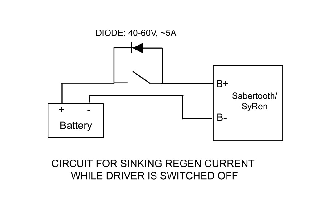
This brings me to my question; How are those of you using the Sabertooth turning off your controller? The battery keeps the board energized and you cant disconnect it because if done the Sabertooth has no place to dump the regenerative power. If the motor is moved by hand the Sabertooth can damage itself if it cant put the regenerative power back into the battery. I can think of a few ways and all will need a switch of some kind and a blocking diode. Something like this:
I'm powering the boards from a 24vdc switching power supply with a 24vdc battery paralleled between it and the boards for the regenerative power to be dumped into.
Different ways to switch I can think of are:
1). A manual switch with a diode across it. This wont work as I don't want to mess with a different off switch for my DC current and my B9 is powered from wall AC current through converters.
2). A low side TIP122 switching circuit operated from EZB and startup scripts from ARC. The Sabertooth is self powered from the 24v power input that supply's the motor voltage. If done like this I'd need to totally isolate all neutral and common grounds going to the Sabertooth / Kangaroo boards and open them at the TIP122 switch. If I try to switch the neutral at just the Sabertooth power input point I still have a neutral feed on the other side through the Kangaroo X2 Where the EZB signal input is attached.
3). A high side switching circuit. I could build one and just switch the hot lead feeding the power input of the Sabertooth and this would turn off both boards. I'd need to use Power MOSFET as the TIP122 may not handle the amperage max I'd be pulling. The TIP122 is only rated for 5 amps and I may pull more then that at times. The Power MOSFET would be able to handle that load. I'm still trying to understand this high side switching circuit. I'm not really sure if I will only need one MOSFET in the circuit or if I need a pre-driver to drive the MOSFET. I've seen drawing of it donn both ways:
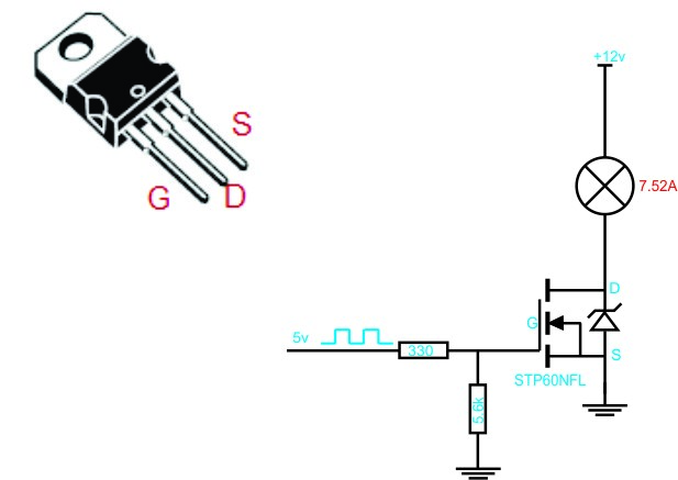
Still not sure which is the proper circuit to use and if I use the pre driver one what values to use. I still need more research to find out. Any recommendations? I'd love to find a High side switch that EZB could control. I did find one at SparkFun but it controlled 4 lines, was a shield type board and cost $60.
4). I could switch the high side with a relay triggered with a Low Side Tip122 switching. This seems redundant and I don't like the long term problems that may arise using a relay. Manly that the contacts on a relay may pit and fail and the relay would be energized all the while the robot is powered up.
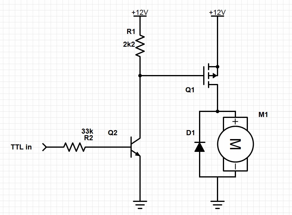
EDIT: Here's the final circuit that works nicely. I've placed diodes in circuit to both let the Sabertooth dump regenerative power back into the battery and also to keep the Sabertooth from back feeding the power supply. Without these diodes the Sabertooth and power supply would stay powered up from the battery after the robot was turned off. Also if the Sabertooth stayed powered after system shutdown the Kangaroo X2 would return errors and not run when the robot was started up again. Seems that if I shutdown near a limit switch and let the Sabertooth/Kangaroo slowly drain the power out of the battery till it was dead these errors would happen. It was very frustrating. Now when the EZB disconnects from ARC this switching circuit will open and shut down the Sabertooth/Kangaroo and the diodes will act as described above. Here's my circiut:
-635323067643352500.png)
I used the resisters listed. With the following Power MOSFET driver and Transistor pre-driver I'm good up to 55v and 19 amps: Q1 MOSFET driver: IRF9Z34NPBF Q2 Transistor pre-drive: 2N3904 Sub the Motor in the drawing for the Sabertooth.
Anyway, sorry for the long post. I'd welcome any thoughts or ideas.
Thanks, Dave

Here's the final circuit drawing that works nicely. I've placed diodes in circuit to both let the Sabertooth dump regenerative power back into the battery and also to keep the Sabertooth from back feeding the power supply. Without these diodes the Sabertooth and power supply would stay powered up from the battery after the robot was turned off. Also if the Sabertooth/Kangaroo stayed powered after system shutdown the Kangaroo X2 would return errors and not run when the robot was started up again. Seems that if I shutdown near a limit switch and let the Sabertooth/Kangaroo slowly drain the power out of the battery till it was dead these errors would happen. It was very frustrating. Now when the EZB disconnects from ARC this switching circuit will open and shut down the Sabertooth/Kangaroo and the diodes will act as described above. Here's my circiut:
I used the resisters listed. With the following Power MOSFET driver and Transistor pre-driver I'm good up to 55v and 19 amps: Q1 MOSFET driver: IRF9Z34NPBF Q2 Transistor pre-drive: 2N3904 Sub the Motor in the drawing for the Sabertooth/Kangaroo combo.
I also went back above in the past posts and added this info and took out the non working circuits.
Hope this helps others wanting to control their robots with a EZB controlled Sabertooth/Kangaroo combo. Have Fun!
Hey Dave... I exclusively use sabertooths for all my robotics.... Granted, I really haven't read up on the kangaroo... what is it used for and why would I need it? I have no issues powering my sabertooth with my ezbs... I just use a regular toggle switch to switch on/off the sabertooth( powered straight from the battery)... I am probably missing something but my simple set up works fabulous with my ezb.... I exclusively use scripts and serial commands to control my sabertooths... I did check power consumption on an idle 2x5 sabertooth (I would assume the 2x10 would be similar)... about 15mA....
The Kangaroo x2 is a daughter board made by the same company that makes Sabertooth that can turn your DC motor into a servo. It plugs into the control side of the Sabertooth. It's takes all the load off the EZB for position and speed control by sending serial commands through only one of EZB's digital ports. Hopefully when the V4 EZB arrives with it's many Uart port I'll be able to get speed and position feedback from the Kangaroo for better control.
As mentioned in the above posts I was having problems when the Sabertooth would drain the battery after power down if it shut down near a limit switch. Then on power up I was getting error codes from the Kangaroo that would lock the controller down. If I shut the system down when the robot was in the center between the limit switches I would not have this issue. I had to find a way to turn off the Sabertooth/kangaroo combo at system shutdown and keep them from being kept alive by the battery till it slowly died.
Also I don't want to flip an extra manual switch to do this so I built this circuit that will let EZB do it through simple scripts and one digital port. When the EZB disconnects the Sabertooth/Kangaroo goes dead.
Hope that makes sense.
Totally makes sense.... I might grab me a kangaroo board now... thanks for the explanation...
Hi Dave I was just fixing to buy the components for your circuit and realized you are using 24 vdc. My motors are 12vdc powered only by the two 12v batteries I have in parallel, would this change anything? (Running the sabertooth 5x25 with or without Kangaroo) Matt
@mdeming1, You should be OK with everything. The only think I'm not sure about is R2. I suggest you set it up on a breadboard like I did and see if it works. If not cut the value of R2 in half. You could go through all the math and stuff to figure it out exactly but it's not like we're building the Space Shuttle here.
@Dave Shulpius Sometimes it feels like I am! Besides, your robot, by the LIP timeline, falls in space shuttle time-frame and it looks at least as advanced as some of the nasa stuff! Just a few questions:
1)Didn't I see a thread you posted regarding the kangaroo where you added a ground wire on the kangaroo or something like that to emulate two way communication? I've been reading so many threads I could be mixing them up.
2)I bounced the circuit idea for my setup off of a friend that is more versed in circuits and electronics than I am. He wasn't as sure about it and thought I'd have to put mine in series which would then cause issues with the motors I have. I'm not sure he really understood the goal and the motor regeneration current from the sabertooth though.
2a)Just to be clear. Is your robot powered entirely by the batteries? Mine is using 12v motors and 12v batteries in parallel with everything powered through the sabertooth.
I bought all of the components I didn't have at Radio Shack yesterday except for the mosfet which I have to get from amazon. I decided to pick up two additional ultrasonic sensors while I was there as well. I couldn't figure why my bill was so high. Turns out they are charging $30 a piece for their U.S., I'll be returning them and getting the EZ Robot ones thank you very much!
Thanks again for all of your help. Matt
Hi Matt,
I'm powering my robot completely with a 24vdc power supply. I have the 24v battery installed so the Sabertooth regeneration will dump the power into the battery and not into the power supply where it will trip it's internal breaker. If you're running off of batteries you really don't need the last complicated circuit I posted. I'd suggest building this circuit:
You can control the on/off switch with EZB using a simple TIP transistor circuit:
Rich has a nice tutorial on how to build one here:
TIP Circuit
Good luck and let me know how you preceded.