Hi gang,
I've been struggling and making slow progress with my rewiring of the DC motors in my B9. I decided to replace all my Pololu H-Bridges with a Sabertooth / Kangaroo combo. The Pololu H-Bridges were very good and did the job but I thought the Sabertooth / Kangaroo combo would make for a simpler setup with easier coding and better performance. well, that's all still to be seen. The coding is easier once you get to understand the serial commands and being able to use the servo controls and scripts in ARC is awesome. However the setup really wasn't that much simpler. I'm still having some issues with error codes at startup that stops any signal input. I'm working with Dimension Engineering to resolve this. I think it may be the potentiometer I'm using. Also I needed to add a battery for some place for the Sabertooth to dump the regenerative power, diodes to keep from back feeding the power supply from the regenerative power and I still need some way to shut off the new boards.
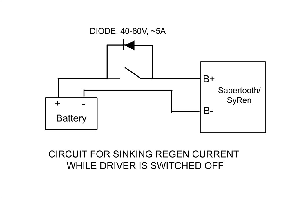
This brings me to my question; How are those of you using the Sabertooth turning off your controller? The battery keeps the board energized and you cant disconnect it because if done the Sabertooth has no place to dump the regenerative power. If the motor is moved by hand the Sabertooth can damage itself if it cant put the regenerative power back into the battery. I can think of a few ways and all will need a switch of some kind and a blocking diode. Something like this:
I'm powering the boards from a 24vdc switching power supply with a 24vdc battery paralleled between it and the boards for the regenerative power to be dumped into.
Different ways to switch I can think of are:
1). A manual switch with a diode across it. This wont work as I don't want to mess with a different off switch for my DC current and my B9 is powered from wall AC current through converters.
2). A low side TIP122 switching circuit operated from EZB and startup scripts from ARC. The Sabertooth is self powered from the 24v power input that supply's the motor voltage. If done like this I'd need to totally isolate all neutral and common grounds going to the Sabertooth / Kangaroo boards and open them at the TIP122 switch. If I try to switch the neutral at just the Sabertooth power input point I still have a neutral feed on the other side through the Kangaroo X2 Where the EZB signal input is attached.
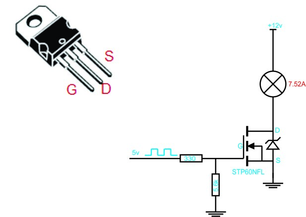
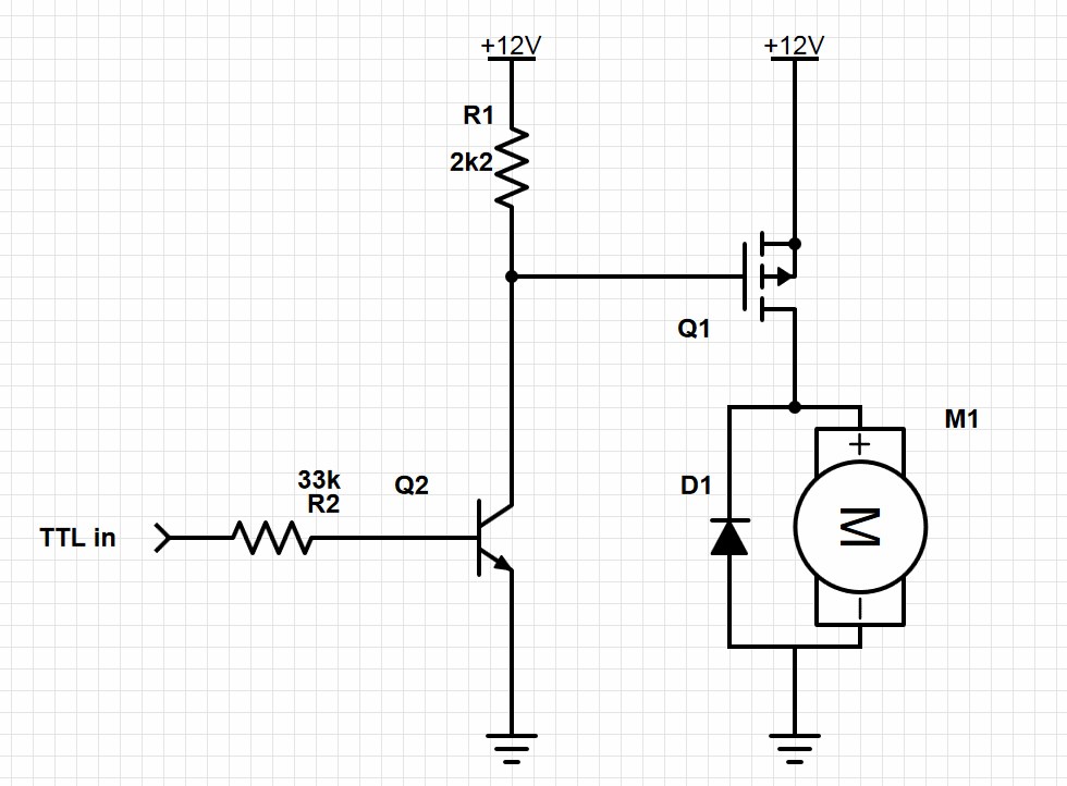
3). A high side switching circuit. I could build one and just switch the hot lead feeding the power input of the Sabertooth and this would turn off both boards. I'd need to use Power MOSFET as the TIP122 may not handle the amperage max I'd be pulling. The TIP122 is only rated for 5 amps and I may pull more then that at times. The Power MOSFET would be able to handle that load. I'm still trying to understand this high side switching circuit. I'm not really sure if I will only need one MOSFET in the circuit or if I need a pre-driver to drive the MOSFET. I've seen drawing of it donn both ways:
Still not sure which is the proper circuit to use and if I use the pre driver one what values to use. I still need more research to find out. Any recommendations? I'd love to find a High side switch that EZB could control. I did find one at SparkFun but it controlled 4 lines, was a shield type board and cost $60.
4). I could switch the high side with a relay triggered with a Low Side Tip122 switching. This seems redundant and I don't like the long term problems that may arise using a relay. Manly that the contacts on a relay may pit and fail and the relay would be energized all the while the robot is powered up.
EDIT: Here's the final circuit that works nicely. I've placed diodes in circuit to both let the Sabertooth dump regenerative power back into the battery and also to keep the Sabertooth from back feeding the power supply. Without these diodes the Sabertooth and power supply would stay powered up from the battery after the robot was turned off. Also if the Sabertooth stayed powered after system shutdown the Kangaroo X2 would return errors and not run when the robot was started up again. Seems that if I shutdown near a limit switch and let the Sabertooth/Kangaroo slowly drain the power out of the battery till it was dead these errors would happen. It was very frustrating. Now when the EZB disconnects from ARC this switching circuit will open and shut down the Sabertooth/Kangaroo and the diodes will act as described above. Here's my circiut:
-635323067643352500.png)
I used the resisters listed. With the following Power MOSFET driver and Transistor pre-driver I'm good up to 55v and 19 amps: Q1 MOSFET driver: IRF9Z34NPBF Q2 Transistor pre-drive: 2N3904 Sub the Motor in the drawing for the Sabertooth.
Anyway, sorry for the long post. I'd welcome any thoughts or ideas.
Thanks, Dave

Don't build anything off my last post. Its a little confusing and incomplete. Rich's sketch is for a low side switch. I show a high side switch. We also need to consider how many amps you may draw. A TIP may not be able to handle your load. That's why I used a MOSFET with a per-driver. This is what happens with only three hours sleep and an adult beverage in you. blush
HI Dave I totally understand the sleep and beverage situations!
I think i'll continue trying to sort out the programming issues first. I got my magnetic encoders yesterday so that is a start, now to see if I can get that kroo to read them.
My last sketch of the high side switch should work nicely for you with the parts I listed. You would just have to remove the Power Converter part the the diode blocking back to it. However I'm just not sure you need to get that complex.
Keep us posted on the progress your making. @Toymake is doing some great work with his Roo / Sabertooth combo and has offered to share his excelent ramping script when he gets his V4.
Did you ever get your V4 yet? You'll need it's two way serial feature if you do any advanced controlling with the simple commands.
Negative on the V4, I only ordered it a week or so ago but I did get an email saying it had moved to the next step in processing. So am I imagining the post where you added a ground underneath the board for two way with the kangaroo? Also, I was looking at this in the kangaroo manual yesterday:
Enable multi-Kangaroo mode (shared signal lines) When disabled, Kangaroo drives the S2 line high when it is not sending data on it, to give a stronger idle signal. One consequence is that S2 cannot be shared.
When enabled, Kangaroo will only drive S2 when it is sending data, and will enable an internal pullup resistor when it is idle. The idle signal is weaker, but S2 can be daisy-chained between them.
would this function solve the two way com problem with the v3 board?
Just some various information that may be helpful:
Three blinks on the Kangaroo x2 is Control Error.
If a motor is powered off and Kangaroo x2 is trying to move, it won't be able to move, so it will think something is obstructing movement and continue to increase the commanded motor power. Once it's at 100% motor power for a certain amount of time and seeing no motion, it will assume it is stuck and throw a Control Error. Technically you can move a pot or transmitter back/forth/back/forth/back/forth (I believe it's three times) to reset this, or with serial reissue a start command.
In DEScribe, this setting is located in Control -> Advanced -> Safety -> Enable runaway detection.
This is for safety because this case (motor powered off, commanding 100% power, no motion meaning no feedback ticks), from the Kangaroo's perspective, is identical to the motor powered on, commanding 100% power, feedback wire has been cut case. That's a dangerous one.
For what it's worth, Kangaroo, when a power down command has been issued, won't throw a Control Error because the control system isn't running in that case.
On Sabertooth 2x32 only, Voltage Clamp feature on P1 and P2 can dump the power to a resistor bank.
Dave, on the Sunshine robot, I really haven't paid attention. But, on the LEAF robot no matter what I did, it would still have a little flashing blue light. It was aggravating. But, I just left it like it was. That is one reason I sort of shyed away from buying another sabertooth. So, I have experienced this as well.
Mel, who are you responding to? Does Dave mention anything about a flashing blue light?... Was not the last post (by James) talking about the flashing leds (representing error codes) on the Kangaroo board (and not the sabertooth...)? So it was the flashing blue light on the sabertooth that put you off of the sabertooth initially? Are we talking about the one you just bought or a previous sabertooth you once had? Don't you think that is rather trivial reason? Are you sure it wasn't because you were having difficulty in getting it to work.....? Anyway, if you don't like the blue light, just cover it with a piece of tape....
Thanks very much @James for the excellent explanation. That's would make perfect sense.
The power down command kinda puzzles me. It seems to do the same as the start up command. When ever I issue a command to move the motor and after that movement is complete, the motor will stay engaged and locked in that position. If I try to move the motor it will fight me to stay in that spot. I have to issue either a Start or Powerdown command to put it in a rest state.
@Mel, I don't think there is a blue led on the Sabertooth. I think it has several leds but change from red to green and and maybe even orange. I'm going from memory so I may be wrong.