Hi gang,
I've been struggling and making slow progress with my rewiring of the DC motors in my B9. I decided to replace all my Pololu H-Bridges with a Sabertooth / Kangaroo combo. The Pololu H-Bridges were very good and did the job but I thought the Sabertooth / Kangaroo combo would make for a simpler setup with easier coding and better performance. well, that's all still to be seen. The coding is easier once you get to understand the serial commands and being able to use the servo controls and scripts in ARC is awesome. However the setup really wasn't that much simpler. I'm still having some issues with error codes at startup that stops any signal input. I'm working with Dimension Engineering to resolve this. I think it may be the potentiometer I'm using. Also I needed to add a battery for some place for the Sabertooth to dump the regenerative power, diodes to keep from back feeding the power supply from the regenerative power and I still need some way to shut off the new boards.
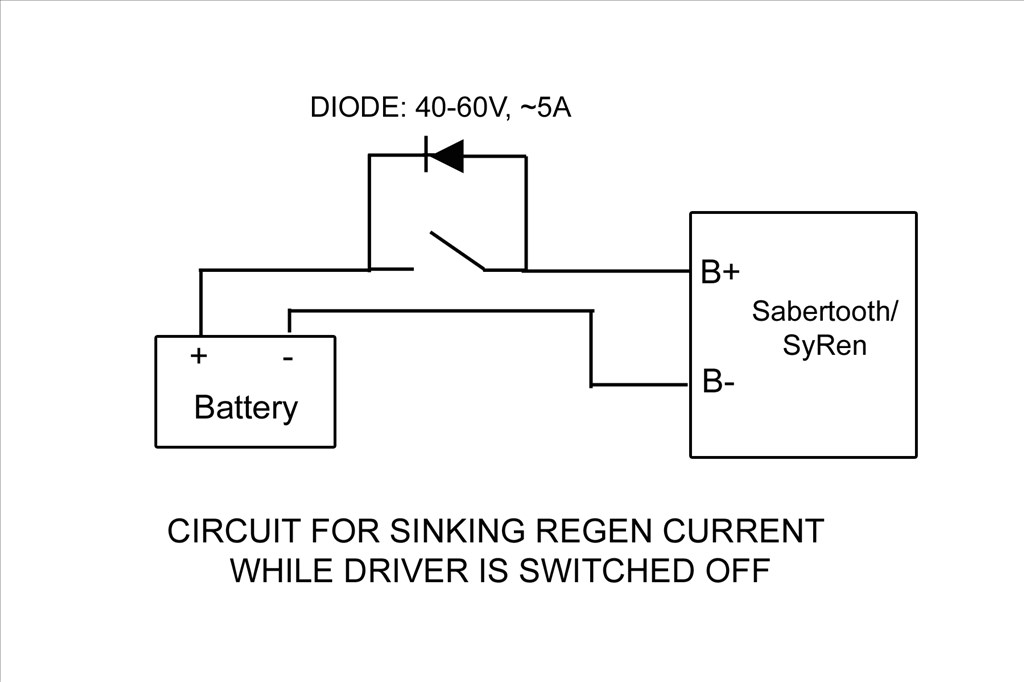
This brings me to my question; How are those of you using the Sabertooth turning off your controller? The battery keeps the board energized and you cant disconnect it because if done the Sabertooth has no place to dump the regenerative power. If the motor is moved by hand the Sabertooth can damage itself if it cant put the regenerative power back into the battery. I can think of a few ways and all will need a switch of some kind and a blocking diode. Something like this:
I'm powering the boards from a 24vdc switching power supply with a 24vdc battery paralleled between it and the boards for the regenerative power to be dumped into.
Different ways to switch I can think of are:
1). A manual switch with a diode across it. This wont work as I don't want to mess with a different off switch for my DC current and my B9 is powered from wall AC current through converters.
2). A low side TIP122 switching circuit operated from EZB and startup scripts from ARC. The Sabertooth is self powered from the 24v power input that supply's the motor voltage. If done like this I'd need to totally isolate all neutral and common grounds going to the Sabertooth / Kangaroo boards and open them at the TIP122 switch. If I try to switch the neutral at just the Sabertooth power input point I still have a neutral feed on the other side through the Kangaroo X2 Where the EZB signal input is attached.
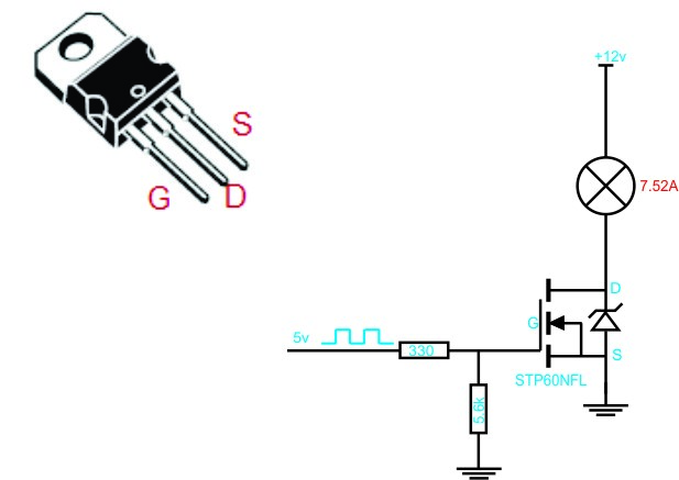
3). A high side switching circuit. I could build one and just switch the hot lead feeding the power input of the Sabertooth and this would turn off both boards. I'd need to use Power MOSFET as the TIP122 may not handle the amperage max I'd be pulling. The TIP122 is only rated for 5 amps and I may pull more then that at times. The Power MOSFET would be able to handle that load. I'm still trying to understand this high side switching circuit. I'm not really sure if I will only need one MOSFET in the circuit or if I need a pre-driver to drive the MOSFET. I've seen drawing of it donn both ways:
Still not sure which is the proper circuit to use and if I use the pre driver one what values to use. I still need more research to find out. Any recommendations? I'd love to find a High side switch that EZB could control. I did find one at SparkFun but it controlled 4 lines, was a shield type board and cost $60.
4). I could switch the high side with a relay triggered with a Low Side Tip122 switching. This seems redundant and I don't like the long term problems that may arise using a relay. Manly that the contacts on a relay may pit and fail and the relay would be energized all the while the robot is powered up.
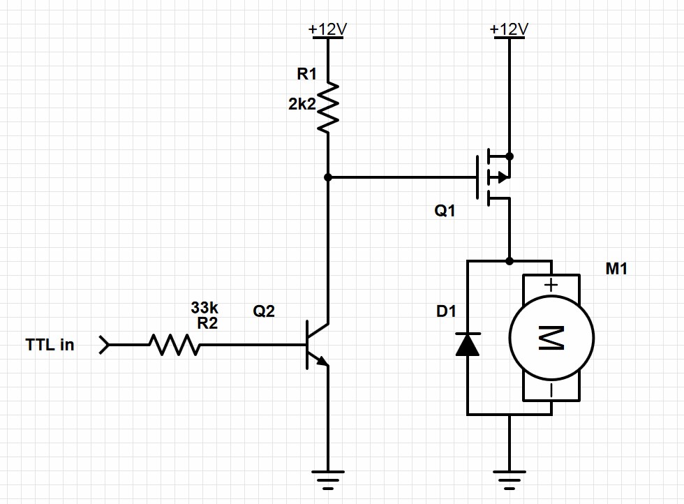
EDIT: Here's the final circuit that works nicely. I've placed diodes in circuit to both let the Sabertooth dump regenerative power back into the battery and also to keep the Sabertooth from back feeding the power supply. Without these diodes the Sabertooth and power supply would stay powered up from the battery after the robot was turned off. Also if the Sabertooth stayed powered after system shutdown the Kangaroo X2 would return errors and not run when the robot was started up again. Seems that if I shutdown near a limit switch and let the Sabertooth/Kangaroo slowly drain the power out of the battery till it was dead these errors would happen. It was very frustrating. Now when the EZB disconnects from ARC this switching circuit will open and shut down the Sabertooth/Kangaroo and the diodes will act as described above. Here's my circiut:
I used the resisters listed. With the following Power MOSFET driver and Transistor pre-driver I'm good up to 55v and 19 amps: Q1 MOSFET driver: IRF9Z34NPBF Q2 Transistor pre-drive: 2N3904 Sub the Motor in the drawing for the Sabertooth.
Anyway, sorry for the long post. I'd welcome any thoughts or ideas.
Thanks, Dave


-635323067643352500.png)

Hey Dave! The sabertooth looks like an awesome board and one day I too may have such a controller as my robot is getting heavy!(wood) Doing a bit of research from the spec sheet for my own curiosity and possibly to help you out. On page 19 the last page is an emergency stop feature it describes tieing all the S2 together and pulling them LOW shutting off the driver! Perhaps that would be a very easy solution! Best of Bot(luck) , Glen
Thanks for the pointer Glen. I'll ask DE if this can be done. I'm useing the Kangaroo X2 and one of it's connector lugs attaches into S2. I'm not sure if S2 on the Kangaroo can be used the same way. Everything I've read says S2 on the Kangaroo is the RX output the way I have it set up. You can see it in the pic below. S2 is the connection point to the far right:
There must be a serial command to power down the Sabertooth! S2 as you pointed out is being used by the Kangaroo!
There is a power down command but the board stays active. They say:
"This command will turn off the motor and control system. You can still read position and speed with the motor powered off. This is used to allow the system to freewheel or to save power. " I;ve used this command and it really does nothing for me the way I'm useing the board.
I asked DE last week about the best way to power down the boards and they sent me the first drawing I posted above.
It doesn't make sense to me to be able to power down the board , yet still be able to read position and speed.?! The first diagram with the switch and diode is the simplest which shuts off the boards while dumping any extra regen back into the battery( while pushing the disconnected robot around ). and the circuits that give TTL logic (which is what you would like, ie "B9 shut down motors" but don't give values for components. I hope some users of the Sabertooth chime in!.....I suspect they just power every thing down with out knowledge or concern of regen energy....
Hi all,
I'm making some progress on my issue. I'm still having problems with control signals not being accepted at start up. However I'm making progress. I've gone from complete lock up with 3 continuous blinking LED lights on the Kangaroo X2 to the board acting like it's accepting signals but nothing moving. I have to power cycle the Kangaroo/Sabertooth boards again after power up and everything works great. I'm working with Demention enegeneering trying to resolve this. So far what has helped was to change my potentiometer from 50k down to 10k and fixing a couple loose connections. The issue only happens when I start up near a limit switch. DE seems to think part of the problem may be the way I power down. Which brings me to my next issue and the one I started this thread about.
As mentioned I want to find a good way to remotely power up the Sabertooth with the EZB and disconnect from the dump battery when the robot is powered down. I really think the best way (in my set up anyway) is disconnect the power feed to Sabertooth on the high side (positive lead). After doing a lot of research and work on a solderless breadboard I found that the 3rd drawing I posted above is the circuit I need to use. With the proper parts in the circuit it works great! I'm able to switch the boards on and off using the positive high side lead from EZB.
EDIT: Here's the final circuit that works nicely (I've replaced the old non working circuit I had posted). I've placed diodes in circuit to both let the Sabertooth dump regenerative power back into the battery and also to keep the Sabertooth from back feeding the power supply. Without these diodes the Sabertooth/Kangaroo and power supply would stay powered up from the battery after the robot was turned off. Also if the Sabertooth/Kangaroo stayed powered after system shutdown the Kangaroo X2 would return errors and not run when the robot was started up again. Seems that if I shutdown near a limit switch and let the Sabertooth/Kangaroo slowly drain the power out of the battery till it was dead these errors would happen. It was very frustrating. Now when the EZB disconnects from ARC this switching circuit will open and shut down the Sabertooth/Kangaroo and the diodes will act as described above. Here's my circiut:
I used the resisters listed. With the following Power MOSFET driver and Transistor pre-driver I'm good up to 55v and 19 amps: Q1 MOSFET driver: IRF9Z34NPBF Q2 Transistor pre-drive: 2N3904 Sub the Motor in the drawing for the Sabertooth.
I'm not sure if it was necessary or I'm just anal but I bumped the pre driver up to a TIP122. I'm just a little worried about the regenerative power coming back from the Sabertooth and back feeding the circuit. I thought the smaller 2N3904 might be a weak link guarding between the EZB and 24v power supply. Anyway, I could be wrong but a bigger transistor couldn't hurt. I also added a couple blocking diodes (not shown) to help block the Sabertooth's regenerative power from back feeding this circuit. I couldn't figure out how to keep backfeed completely out of the circuit but at least I'm back feeding it from the front end and not the back end.
Next thing will be actually building the board and installing it. Perhaps after being able to turn off this board at power down and then power it back up with the EZB after the robot is active will solve my control problem. I'll keep ya all posted.
Glad to hear things are working out! I guess the ultimate way of isolating dangerous back feeds etc is with an opto isolater. Your provided circuit is very useful for everyone! Going forward........
Hey Glen, when I get the circuit finalized I'm going to try to learn how to use that circuit designing web site Rich and others have mentioned. I'll try to draw up a decent schematic of how this circuit is built. I think this high side switch circuit along with the low side switching circuit that can be controlled by EZB are something that all robot builders would find handy.