Hello,
I made the leap after a fair amount of research and bought an ezbv4 last night. My initial application is static so I deferred buying a battery..unless I missed it I did not see a wired power adapter in the store. I have read some of the power tutorial.. I did get the power base also.
I am looking for a recommendation on finding a power supply.
I expect to eventually run 18 micro servos and possibly up to five brushed motors. Three of these are larger and draw 1.8a stalled.. I never expect to have all the servos running at once.. I plan to have the. Brushed motors running through escs so their power can be drawn from another source. If you follow.
I want to make sure I have something soon.. So to start I could use a dc wall wart say 12 volt 2amp with 2.1 mm barrel?
Can someone throw out some links to recommended sources? I am inclined to go to one of the mote prominent online robot shops. Does that make sense?
Asked
— Edited
First, when you say "not all servos are r running at once". What does that mean? To clarify, are you saying that you will Release the servos? Or they won't be "moving" at once? Because how a servo works is not like a regular motor. When a servo is "holding position", that is a stall torque + holding weight. A servo, even when not moving, is actually using a great deal of current holding position. This is of course when holding weight. A servo in position that is not holding weight, won't be using much current because the motor isn't running to hold the weight.
That's the difference between a servo and a motor. Forgive me if you actually meant that the servo will be released and not receiving a PWM signal to hold position. Many people are lost when it comes to servos. Here's a tutorial on how a servo works (the learn section is your friend): http://www.ez-robot.com/Tutorials/Lesson/48?courseId=1
As for the power supply, 2 amps won't be enough for much - maybe 2 servos. Unless the power supply is a switching supply, because most are transformers which are made for transistor circuits. There is a wack of information on this forum about power supplies to use - and user tutorials about them. Now, the biggest challenge you'll run into is assuming a "wallwort" can provide current for anything mechanical, even if it has a kabillion amp rating.
This is because transformers, again, are generally designed for transistor circuits - and the load of a mechanical device (Such as a motor or servo motor) will affect the whole circuit. It's inherit to how a transformer works - this is why switching power supplies have been invented (and due to lower power consumption/heat)
Here's Steve's tutorial: http://www.ez-robot.com/Tutorials/UserTutorials/163/1
Here's techno's tutorial: http://www.ez-robot.com/Tutorials/UserTutorials/170/1
There may be some others, look here: http://www.ez-robot.com/Tutorials/UserTutorials/
Also note. as dave cochran just mentioned - the EZ-B ports aren't regulated. This means power in is power out. You will find out more by reading the EZ-B v4 datasheet, it's in the learn section as well. Here is a direct link to the ez-b v4 course: http://www.ez-robot.com/Tutorials/Course/5
I have a Meanwell 5V 60amp power supply that is barely able to power my inMoov. On occasion I still get browns out causing the ezb to reboot....
and the basic learning lesson
Lesson 13
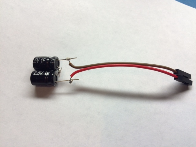
I am a noob to all this. Obviously. Much of my reading had been on arduino and when they showed all these servos running they didn't mention power much.
So, I only have a couple servos to play with and a servo tester. Specs on the servos are hard to come by. Can't find how much the 'inrush' draw might be let along operating draw. These and the ones I have looked at seem to be 3-6v, so based on that and comments here and more reading I see I really want a 5v or 6v supply MAX?
Here's one servo I was looking at:
http://www.hobbyking.com/hobbyking/store/__22927__HXT900_Micro_Servo_1_6kg_0_12sec_9g_US_Warehouse_.html
and I think I may end up needing a second supply then for the brushed motors I want to run with the ESCs.
Here is the ESC:
http://www.hobbyking.com/hobbyking/store/__9090__Turnigy_20A_BRUSHED_ESC.html
Looking at this 5V:
http://www.jameco.com/webapp/wcs/stores/servlet/ProductDisplay?langId=-1&storeId=10001&productId=123394&catalogId=10001&CID=MERCH
It's half the price of the EZB.
A lot of these say 'single' output but it looks like they have seven screw terminals.
The picture is kindof small but it looks like two V+ and V- but can't make out the others. Note says picture may not be exact. Datasheet does not clarify that aspect.
Here are the terminals pin assignments for the mean well supply in your last link from their datasheet...
1.) A/C input live
2.) A/C input Neutral
3.) Input Ground/Earth
4.) DC output Ground
5.) DC output Ground
6.) DC output Positive
.7) DC output Positive
Servo inrush is difficault to measure as it happens so quickly which is why you won't see it very often in spec/datasheets. As has been mentioned, it's probably best to go to the higher end of the scale for the servo power specs. If one is rated for maximum 6v input, grab your self a 6v supply.
I use two similar micro servos (in your first link) which I had laying around, in my current robot project, but rated at 5v to 7.4v Max using a 7.2v battery and they work great at that voltage. Using less than 7.2v with the ones I use and the servos begin to jitter slightly and have trouble moving or holding anything near the maximum specified stall torque.
I am not having much luck finding a power supply at 6v.
I was looking hard at the meanwell line which seems very extensive yet and it seems they have 5v, 7,5v, 12v and many more higher, but not seeing 6V! But it sounds like my servos may jitter at 5v and at 7.5v I could fry them.
So... do I have to get a higher output supply and then get something like this?
A step-down voltage regulator:
https://www.pololu.com/product/2852
Or perhaps this step-up/down voltage regulator:
https://www.pololu.com/product/2575
I only mention servo jitter at 6v because that's what I experienced on a 7.4v micro servo of the same brand some time ago. Chances are that a 5v supply will be okay with your 5-6v servos. Most servos like that will work okay at 5v, where giving it the maximum 6v will make it a little stronger. You could use the regulators/drop-downs you linked to, but it would have to be one per servo.
I ended up using two 1Farad 2.5V Aerogel caps in *series to boost the voltage rating to 5V.
Then you can place the caps on the GND & 3.3V pins next to the analog pins.
Be very careful you get the polarity correct or the caps could explode
oops I made a mistake those caps are in series, edited post.
Wouldn't it make more sense to put the smoothing Cap's across the supply to the Servo's, as it's the servos that are causing the current spikes!
I know you will have to have a higher voltage rating for the Cap's.
Also the rule of thumb is to have the voltage rating of the smoothing caps at least 30% over the supply voltage, your using.
Chris.
the main power supply to the Servo's and EZB.
It may work OK the way he suggests, BUT what I was suggesting was to put it across the main power source, obliviously you need to be mind full of the voltage rating of the Cap's to use.
Unless I missing something here? but I do know what I'm talking about, I have been working in the Electronics design industry for over 40 years, and have a degree in Electronic design and engineering, and voltage smoothing is pretty basic stuff!
Chris.
Here's are the reasons:
1. Servos have a extremely high in rush current demand. In order to smooth out their voltage drop (on the input side) requires a proportionally high amount of capacitance. I literally used every high farad capacitor in my collection (30 or so) placed in parallel (capacitance adds in parallel) to try to smooth out the input voltage and it barely made any positive results. These findings were discouraging because I didn't want to have to chain together a massive bank of caps to rectify the issue.
2. Voltage rating versus capacitance - capacitor voltage rating needs to be matched or exceed (better practice) the voltage being applied. In the case of using a 7.5V supply you would need at least a 7.5V rated cap. But here's the catch: the higher the voltage rating on a cap the larger in physical size and the more expensive it will be. To use low voltage super caps on the voltage input we would have to place many in series to get up to the voltage rating we need. Here's the next catch: when capacitors are added as the voltage rating increases the capacitance decreases as the farads are being divided, so you have to start paralleling caps to increase the capacitance again. You can see how this could quickly become a ridiculously large bank of caps.
3. Cost - to acquire large capacitance values these days Super Caps are the answer but to create a large bank of Super caps is very pricey.
4. Size - a large bank of super caps also takes up space which is usually a commodity in Robots.
All this being said I found it far simpler, smaller, and more economical to place Super Caps on the regulated output side of our SWPS to account for dips on the input voltage side. In Rush voltage dips only happen for fractions of a second so as long as the Supercaps can hold up the 3.3V for the time needed it all works out.
Anyway, that's my working theory in my robot. I've proven this in my build by using both techniques. I'm not saying caps are the wrong way to go. I'm just offering another option. Too me though caps seem like placing a bandage on a wound to keep the bleeding from happening.
@Jeremie, if you're still doing tests perhaps you could try my method to confirm my findings? Really load the PS down and battle test it by bypassing the EZB to see when the PS browns out vers running supply power to servos through the EZB using caps in the ADC pins?
Thanks for chiming in, you do bring up some valid points! Having proper gauge wire and a good quality power supply are very important in the quest to eliminate brownout conditions. Although, I would contended that it's easier to add a couple caps to the 3.3V than rewiring your entire project for external power, but that might just be my preference :).
What we are really taking about here is the limitations of switching power supplies/supply and demand. If the power supply cannot supply enough current to meet the demands of the application it will drop the voltage to compensate (and cause a brownout) this is the nature of switching power supplies (SWPS).
In the majority of the brownout cases the EZ-B's power traces are not to blame, it's is highly likely that it is a case of a power supply that cannot meet the inrush current demands of the motors (DC or servos). How do I know this? Well I can run the same amount of current through the EZ-B with a high Ahr LiPo or Lead acid and it will work without an issue. I have also seen cases where no 2 power supplies are the same (quality matters) 20A doesn't always mean 20A. Meanwell is a brand that I've had great experiences with, their rating is trustworthy.
The only caveat to all this is what the real current (inrush and constant) is for each project. The EZ-B isn't a magic machine it does have a theoretical maximum amount of inrush and constant current it can handle its just hard to nail down. Instaneuos inrush current is very hard to measure and with constant current we are dealing with thermal properties and resistance. That being said, using ezrobot servos I have not found a situation where I cannot power an robot (even with 16 servos) through the EZ-B with a SWPS.
The key for a lot of people is that they want to use a lower current rated supply than is needed due to expense. Adding super caps to the 3.3V line allows you to do this. The real fix is a higher current SWPS (but yeah they are expensive).
Thanks for the info! I purchased 2x 1.5F 5v supercap's which has internal balancing circuity. Put them in series to get 10v rating, I used them on my Inmoov with EZB controller 'INPUT' voltage side ( 7.4v ), works a treat and stops intermittent brownouts.
Also these supercap's wasn't expensive, at £4 ( $6 ) each.
Cheers,
Chris.