Asked
— Edited
Servo External Power Pack
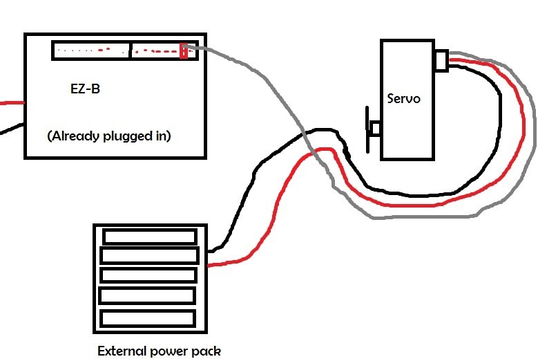
Does anyone have a diagram of a servo set up with a second power source?(Eg. Heavy duty servo)
 EZB Stress Test
— Stress-tests EZ-B controllers (UART, ADC, voltage, temp, audio, digital I/O) to detect disconnects, corruption and stability issues.
Try it →
EZB Stress Test
— Stress-tests EZ-B controllers (UART, ADC, voltage, temp, audio, digital I/O) to detect disconnects, corruption and stability issues.
Try it →
Does anyone have a diagram of a servo set up with a second power source?(Eg. Heavy duty servo)

https://synthiam.com/Community/Questions/2959
Check my post in that topic out.
Could you show me using this?
Got a little confused on the other post.
Feel free to modify this directly to show.
Basically, red & black from the servo just connect to a 6V supply. White connects to the EZB.
Easiest way of doing it is to snip a servo extension's red and black wires on the male end only (the end that attaches to the EZB) and connect these to the 6V power source by whatever means, stripboard like my example, barrier strip, crimps, etc.
Take the red and black from the servo attaching to the red and black of the battery. now I'll take the white of the servo and attach it to a signal pin of a digital signal port. Tie all your blacks together.
Ok so farly easy.
Thanks Rich.
And you dschulpius
I have used this on all of my bots and it works fantastic! And so simple to do.
Ok so just double checking. Like this?