
Reducing Speed For My Robot 12V Motors
Hi there.
My name is Steve and I am new to the forum so I would like to say hi to everyone. I do have a question I hope someone can help me with regarding my current robot build so I hope this is the right place to ask. I am in the middle of building my own version of a full size K-9 with a few differences that I will put up on the EZ Robots showcase pages when he is completed. I am currently waiting for my EZ goodies to arrive which are due sometime this month (June, 14) and so far I have pretty much completed his body and rolling chassis.
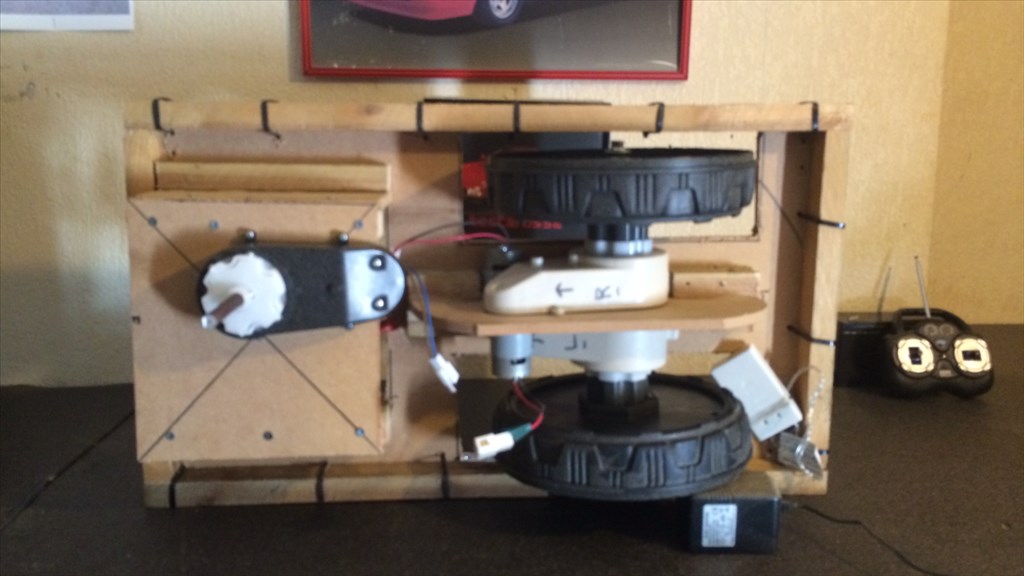
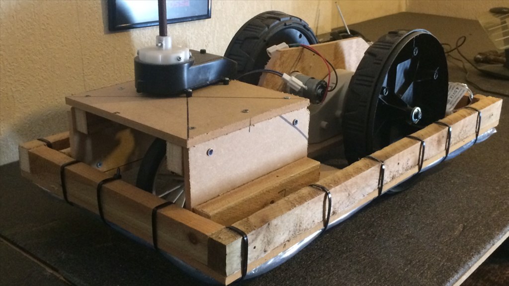
The question I want to pose has to do with the rolling chassis/drivetrain. The parts for the chassis have mainly come from a kiddies ride on car which has two 12v, 30w drive motors which produce two fixed forward and reverse speeds (slow 3MPH and fast 5MPH) and a single speed 12v steering motor, connected to a control/radio control receiver box, controlled by a R/C controller and powered by a 12v 7Ah rechargeable battery. The R/C controller will be located inside the body and 2 servos via the EZ-B will move the joysticks for the movement (one servo for forward and reverse, and the other for left and right).
I have this pretty much sorted, but hear is where I need the help confused. . I want to slow all 3 motors down a bit. I would like to have the steering motor turn slower so there is more precise movement via the servo control, and would like to be able to adjust the speed of the drive motors so I can have a slower, almost a crawl, speed while K-9 is roaming the house, and then be able to readjust the speed so he can move quicker around larger area or open spaces. The current "slow" speed is about 3 MPH but it is just a bit to quick to navigate autonomously around my house so I'm looking for a hopefully simple solution.
I had an idea of simply splicing through one of the motor wires on each motor and wiring in a 12v potentiometer which I could attach to his control panel and adjust it/them as needed (or even servo controlled, but first things first). Could it be as simple as that or would I need something more? I have also read online about maybe using a PWM but I wouldn't know how to wire it (or them as the case maybe) up. Would using a PWM do what I'm looking to do and would it even work on the set up I have?
I am not really experienced in using or installing resistors or soldering circuit boards ect so a simple "easy for me to do" solution would be great, so any help and advice or solutions anybody here can offer really would be appreciated, and thanks in advance  .
.
Steve

Steve, I have seen people setup a motor controller for the ez-b and still use rc control while switching between ez-b and rc. servo control wouldn't be as accurate or safe, as the servo could get stuck. I will have to dig to see who did this setup but its do-able.
Slowing down the motors can be done 3 ways.
Yes I know its a fixed speed but if you decrease the voltage it will start to respond.
The l298n motor controller from ez-robot comes with ez-plug wires which remove soldering. there's one area you may need to solder put it isn't hard.
Tech.
A proper motor controller is your best bet... I prefer the Sabertooth because it doesn't get much eaier than that... Others like using (as Tech suggests) a l298n H Bridge....
Thanks Technopro and Richard for the lightning speed responses. I do agree with your points regarding servo control. I must admit that was something I failed to think about and see your point. so as it stands at the mo, @ Technopro, when you say using a regulator, do you mean something like a potentiometer? I appreciate you looking for the R/C and EZ-B set up. Sounds interesting.
I would me more than happy to do away with the R/C side of things and use the existing motors and battery via a more accurate controller but I am very new at making a robot at this kind of level (this is my first infact) and have never used sabertooth, arduino or EZ-B (the developers kit I am waiting is my first) so not sure how it would go together and play nice with each other without it being to difficult for me to do.
I just had a look at the EZ Robots motor controller and looks interesting. Can I simple run my existing motors through that instead? If so, what about powering the motors. Can I run the 12v battery that came with the motors through it? And finally, if all this is possible would this give me full control over motor speed for example the steering motor (essentially turning it in to a servo of sorts)?
Thanks for the advice so far though guys.
Steve.
If your motors don't take more than 1.2 amps each your fine. When I say regulator I mean a voltage regulator like this one: www.ebay.com/itm/4-38V-to-1-25-36V-DC-Buck-Step-Down-Converter-DC-5V-12V-5A-Car-Voltage-Regulator-/141304859710?pt=Motors_Car_Truck_Parts_Accessories&hash=item20e66d0c3e&vxp=mtr
I think it was rgordon who made the rc/ez-b flip-flop setup for the sabertooth 2x12. I think his questor project used it. Not 100% though. Here's a link to where he explains it: ez-robot.com/Community/Forum/posts.aspx?threadId=4766
Yes, using a motor controller will allow you to do a tank like setup as well controlling the motor speed.
I recommend using the hbridge that we sell. It's based in the l298 chipset. It works well with the PWM hbridge control. That control lets you manage speed and very smooth arcing turns.
Thanks for finding the info and for the links Technopro. I'll have a look.
Thanks for the info DJ. Forgive my ignorance but when you say hbridge, I take it you mean the 2.5 Amp Motor Controller? I'm still learning all the terminology . I do have a couple of other questions I would like to ask you if you don't mind. How would the motors be powered. Can I put the 12v battery I have through it, or is it powered via the EZ-B power pack?
Thanks in advance buddy.
Steve.
The l298 can run on the same battery as the ez-b. If the motors are 12Vs, attach the 12v from the battery to the motor controller.
This is basically how you hook an H Bridge motor controller up to motors and the ezb... There may be a few minor variances, but basically this is how it's done...