
unclemike
USA
Asked
— Edited
Radar Hookup Question
UncleMike here again; I am having a problem (yes I read the post by angpal59, and have not found any other posts relative to this ) getting a signal from my ping unit. I have hooked a 3 wire connector (as supplied in the kit blk,red,wht) black-5v, red- grd. white to trigger and a separate white to echo (by the way DJ in the ultrasonic tutorial video says the middle pin is ground but that is not how the board is labeled) I have set the trigger to D0 and the echo to D1 and the servo to D2, (servo responds correctly) the panel shows the changing servo settings but the distance shows 20 and does not change when I change the distance my hand is in front of it, nor does the graphic show "pings" Any ideas? UncleMike

If the distance reads constant then you more than likely have the trigger and echo mixed up. Also start with D1 and use d2 and d3. D0 has different abilities. Use a meter and check to make sure you are getting 5v to the power with a multimeter. Be sure you are using 60/40 rosin core solder. Using lead free solder can cause a cold solder joint without a specialized soldering station.
Also if you short your trigger to ground or echo to ground you can damage the ultrasonic sensor permanently so be sure your safe from static electricity and everything is unplugged when making changes.
Tried D1 and D2 with the same results also tried ping distance and get the distance value of 20 from both. 5 volts at the board and at the SR01. all solder joints solid, I only use 60/40. Also tried a Sharp 2D120X IR unit it works in collision mode stopping the servos but in ir radar mode I get very strange results (in mm maybe?) and does not interact with the servo movement panel. label me confused UncleMiike
PS can a parallax ping (3pin) be used with the EZ-B?
The ultrasonic sensor get burn or short out really easily. All it take is a simple mix up between your echo and 5v port for it to be stuck at 20. I am speaking for personal experience, I probably burn about 5 so far in less than 3 months, with careless mistakes. Now I simply purchase them 10 at a time for about $8 on Ebay. Sometime I even receive one or two already shorted and stuck at 20
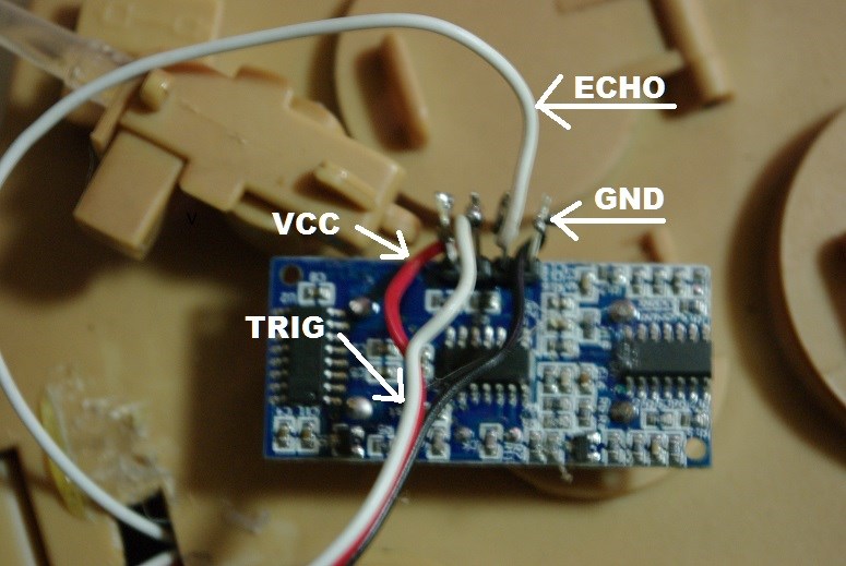
keep in mind that on the EZ-B board, it goes as Ground, 5v + , trigger ( D1) Echo (D2)
On the ultrasonic sensor the inputs are Ground, Echo, Trigger VCC
I assume you use a normal 3 wire connector without modifying it. So you had
Ground to ground ( D1) 5V + to echo ( D1) trigger to trigger ( D1) Echo to VCC ( D2) Above it where you probably burn your sensor
it should had been
Ground to Ground ( D1) 5V to VCC ( D1) Modify wire connector here trigger to trigger ( D1)
echo to echo ( D2)
trigger to trigger ( D1)
echo to echo ( D2)
I am at work, can't really give you a visual image, if still need help later, will post visual.
Check for shorts between pins.
If you have Echo and Trig backwards it will read 255. If it's not detecting anything (i.e. broken echo or trig wires, cold solder joints etc.) it will read 255. Reading 20 indicates that the sensor is damaged or there is a short.
I've grown to love the premade jumper cable kits. Just push on then pins and go! ( drives me nuts my phone edits my words when I submit a comment. Sometimes things don't make sense)
Yep, I too have a new found love for jumpers with the correct male or female ends on, so much easier and reusable. No risk of soldering problems. Just a shame JST crimp tools are stupidly expensive over here.
Am I reading this right or did he say "black-5v, red- grd. white to trigger and a separate white to echo" which would mean he's powering it backwards. Black should =gnd and Red should =5v. If he did go black to 5v and red to gnd its possible that he shorted it out and now it reads incorrectly.
And @UncleMike, are you asking if theres a way to use only one port on the ez-b for the ping sensor? Unless your a programmer, no. The ARC control requires one port giving the trigger and another giving the echo.