
Asked
— Edited
Pressure Sensor
Hello,
i build the InMoov (like some persons know) ;-)
and i have build in some pressure sensor
these ones:
https://www.conrad.de/ce/de/product/503368/Drucksensor-Interlink-FSR400-ca-10-g-10-kg
the FSR400
but good question... how i can connect this sensors to the EZB4 Controller that if i push to the sensor a servo stops?
And how will look the script?
thanx a lot
Boris

I found an English PDF file on this series of pressure transducers here. Looks like all you have to do is add a resistor and a voltage source then connect the junction of the resistor and the transducer to an ADC port. What size resistor you will need will depend on the range of force that will be applied to the transducer, I would suggest experimenting with it before hooking it up to the EZ-B.
Apparently the transducer has an amazing resistance change range, 1 mega ohm down to < 3K ohms. Though the PDF file seems to indicate more like 10 mega ohms. Here's how you would hook it up for testing. Get a resistor, about 100 K ohms could be good to start with. Attach one end to the negative lead from a power supply or battery source. Using two AA cells in series would be good since that would give you 3VDC and the pins on the EZ-B are 3.3VDC. Attatch the other end of the resistor to one end of the transducer. Then attach the other end of the transducer to the positive lead of the power. Hook a voltmeter across the 100 K ohm resistor (negative to the negative of the power source and positive to the junction of the resistor and the transducer. The meter will read some small voltage (about one tenth of the applied voltage, assuming 1 M-ohm unloaded). Apply force to the transducer and you should see the voltage go up on the meter.
To hook it up to an ADC port on the EZ-B you will need to attatch it like I described above, but to the pins of the ADC instead. The pin with the black colored plastic beneath it is the negative and the pin with the red plastic below it is the positive voltage. The other pin goes to the junction of the resistor and the transducer.
As far as programming goes, you can use the GetADC () Script instruction. For example: $CurrVoltage = GetADC($ADCPortNumber). Then you can compare this value with some value between 0 and 3.3 to use as a "trigger" for whatever action you want to happen. For instance:
$MaxVaue being a voltage between 0 and 3.3V. What the value is that you will use depends on the output of the transducer for a certain amount of force applied to it. You will have to see what the value is with no force applied to the transducer. Then apply some force and see what that value is. You can use the ADC Value Control from the ADC Controls section to see the voltage in ARC. If you can't get enough voltage for a given force applied to the transducer, you can try a higher value of resistor.
Hope that helps.
Hello WBS00001,
thanx for you cool and huge Help,
I understand slowly how it works.
Do you maybe can post an electric plan for installtion to the EZB.
I know it easy to do this installtion, but to go shure a pic can say more then thousand words.
Thanx you so much!
Boris
@rentaprinta.
The following link, in post #29, may be of use to you. I connected up some flex sensors recently which are very similar to the pressure sensors you are using...
Flex sensors
Hope that helps.
Hello Boris;
Yes, I can create a picture for you to help, but all it will be is showing is an extension cable with one end cut off, wires stripped, and the resistor and the transducer, along with an image of the EZ-B showing a typical connection point (and ADC 2-pin connection). Is that what you are looking for?
Also, I looked into the use of this transducer more and limitations of it. There are things to keep in mind.
1)This is NOT a strain gauge, load cell, or pressure transducer. Trying to use it to actually measure force applied can be very difficult. Also, the only actual sensing part (sensor) is the round section. The long, rectangular part is only for connecting to the sensor area. That part is meant to be bendable. Not the round part. So do not think that you will get a reading by bending the rectangular part. That being said, you may get a change in reading when you bend the rectangular part, but that will only be because it is physically connected to the sensor part. Bending the rectangular part could cause some distortion of the round part, causing a change in resistance. My point is, that if you were getting the one with the long rectangular part because you thought that would give you a long part to bend to get results over a long area, that is not going to work out. You probably don't really need that particular unit.There is a version with just the round part and connection pins if you need something more compact.
3)As I mentioned in point 1, it is difficult to get repeatable results from it because so many things can effect the change in resistance with a specific force applied. For instance it must be mounted to a flat, smooth surface (no bends) with no air bubbles beneath it. Again, I'm talking about the round (sensor) part of it. The long rectangular part can mount to a curved surface. They recommend using thin double sided tape like Scotch brand double-sided laminating adhesives. The type that is like regular tape but has glue on both sides. Be sure to cover the entire area of the transducer with the tape. It's not going to work very well if applied to something like the palm of the robot's hand, for example, to measure the force being applied by the robot when it grips something. Also, do not use cyanoacrylate adhesives (e.g. what we call Super Glue or Krazy Glue) or solder flux-removing agents to any portion of it, top or bottom.
4)Never let sharp objects come in contact with it. In fact it is best to cover it with something rather than letting things contact the surface directly. Soft rubber is recommended.
5)Do not solder to the connection pins or the silver traces going to them (the long, rectangular part). You must use a connection device such as a zero insertion force (ZIF) connector or an AMP type connector. We call them "flea clips." Basically, only use something you can plug them into. It's best to cover those points with shrink wrap tubing or electrical tape as well.
There are other things, but that covers the major ones.
Hi Steve,
Hi WBS00001,
so i made a little installation,
Update: It's a 10K ohm
and made a new project with ADC Meter:
Like you see i got only 0,88 to 0,90 Volts on the ADC Meter.
I can push my pressure sensor so much i can, but no changes.
I check with a Multimeter my Pressure Senors and it ok!
So something wrong with the wires?
Boris
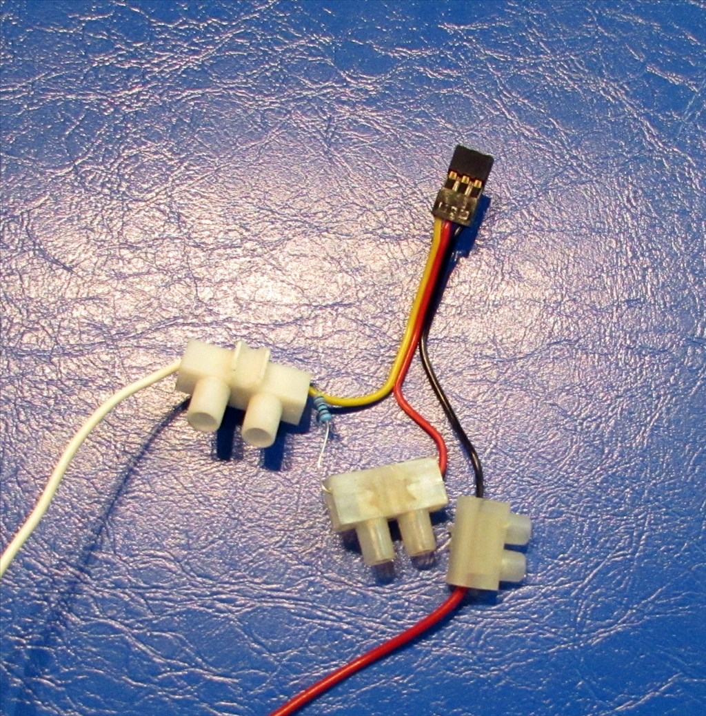
Correct me if I'm wrong anyone, but shouldn't the resistor be connected between the yellow signal and black ground or red Vcc wires, and not between the black ground and red Vcc wires as in the photo?
That's how I did it with my "Flex" sensors...
From your picture the resistor is between ground and +3.3v.... it should be either between ground and yellow signal (pull down) or between +3.3 and yellow signal (PullUp)
Hello again Boris;
Unfortunately the picture doesn't show the connections of the sensor but I am assuming the white wire is connected to the white wire on the connector block and the red wire is going to the red wire on the connector block. When I say "connector block" I mean the white and clear blocks shown in the picture. Also when I say "plug" (below) I mean the black connector shown in the picture.
Anyway, If my assumptions are correct about how the sensor is connected, you need to make the following change:
The yellow wire on the plug should be going to the ADC input. Move the resistor from where it is in the picture to the yellow wire on the plug. Just swap it from the connection block it is in now to the other connection block, connected to the yellow wire. The other end of the resistor is fine as it is.
To make it a bit more uniform, you might want to also swap the red and white wire coming from the sensor (where they go into the connector blocks) so that you have red going to red on at least that one. It will work either way but that just makes the color code of the wires make more sense.
Plug the black connector into the ADC port, being careful to make sure the black wire goes to the pin with the black plastic under it. Try again.