kbb0118
Hi all! I'm new here I've been lurking for some time as I assembled equipment. My plan is inspired by DJ's snow shovel bot and Ampdroid and a few others.
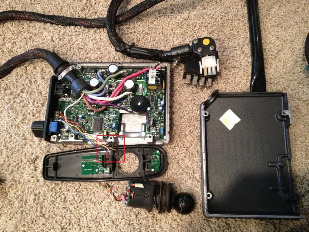
I'm using a Pride Power Wheelchair Jet 2. I've pried apart the controller - the joystick is connected with a 6-pin connector. I've cut the joystick off - although it worked, it was bent and hard to use. Below in the photo I've red box'ed the cut ends. By process of elimination I believe the red and black wires on the 6-pin are power to the joystick PCB, so I have left those disconnected. That leaves 4 wires, which should be right motor +, right motor - , left motor +, left motor -.
I tried connecting each of the 4 wires to the signal pins D0, D1, D2, D3 of the EZ-B and attempted to send a signal to operate the motors, but nothing I tried worked. I tried EZB Controls for HBridge Movement, Modified Servo, Horizontal Servo, HBridge and servo speed. Anyone have any ideas? I'm totally new with the EZ-B software so I'm sure I'm doing something wrong. On the HBridge Movement I tried every combination for the 4 signals.
My original plan was to use a Sabertooth 2x25 - I have it in hand, but this would be so much cooler (easier) if it worked!

I have tried and tried and tried to use the controller that came with the wheelchair. Wasted sooooo much time it gives me a headache just thinking about it. stress Even with the Sabertooth it's going to take a little time getting the speed right, if your not using full speed. My 2 cents, go with the Sabertooth.
If by chance you do get the controller working, I would like to see how you did it.
Herr
Yes go with the Sabertooth controller. 2 x 25 amp sabertooth H Bridge
https://www.dimensionengineering.com/products/sabertooth2x25
The Sabertooth 2X25 is one of the most versatile, efficient and easy to use dual motor drivers on the market. It is suitable for high powered robots - up to 100lbs in combat or 300lbs for general purpose robotics.
Out of the box, the Sabertooth can supply two DC brushed motors with up to 25A each. Peak currents of 50A per channel are achievable for a few seconds.
Overcurrent and thermal protection means you'll never have to worry about killing the driver with accidental stalls or by hooking up too big a motor.
Sabertooth allows you to control two motors with: analog voltage, radio control, serial and packetized serial. You can build many different robots of increasing complexity for years to come with a Sabertooth. Sabertooth has independent and speed+direction operating modes, making it the ideal driver for differential drive (tank style) robots and more.
The operating mode is set with the onboard DIP switches so there are no jumpers to lose. Sabertooth features screw terminal connectors - making it possible for you to build a robot without even soldering.
Sabertooth is the first synchronous regenerative motor driver in its class. The regenerative topology means that your batteries get recharged whenever you command your robot to slow down or reverse. Sabertooth also allows you to make very fast stops and reverses - giving your robot a quick and nimble edge.
Sabertooth has a built in 5V 1A Switch-mode BEC that can provide power to a microcontroller or R/C receiver, as well as 3-4 standard analog servos. The lithium cutoff mode allows Sabertooth to operate safely with lithium ion and lithium polymer battery packs - the highest energy density batteries available.
Sabertooth's transistors are switched at ultrasonic speeds (32kHz) for silent operation.
Sabertooth 2X25 uses 1.3 milliohm MOSFETs in its bridge. Going by our competitor's ridiculous rating schemes this would make it a dual 190A motor driver!
many builders use these guys so there is lots of second hand knowledge.
Using the Analog read controls in the EZB I recorded the volt settings for each of the 4 joystick wires when in these positions: Off, Neutral, Forward, Reverse, Left and Right (see table below). I ought to be able to program movements using PWM controls no?
I understand the virtues of the Sabertooth (I did buy one after all), but with the photos and wiring diagrams I've unearthed from posts here, I still can't tell how to wire the Sabertooth so that I do not lose the on-board battery charger. Plus the chair controller has battery power meter, power button, speed control knob, and parking break. I'm going to give the chair controller a tiny bit more effort before I give up and go with the Sabertooth.
@kbb0118 First off, welcome to the forums, glad you could join us in the discussions!
In order to make use of the joystick circuit to control the motor drivers onboard you will have to figure out how the joystick functions. I am guessing that it is an analog Joystick with a potentiometer on each axis for the 'x' and 'y' (left/right & front/back)directions, that way the user would have had variable speed at their control. This is the same way game controller analog thumbsticks work. So in order to use the EZ-B to emulate way the joy stick worked you'll probably need to do the following:
First grab an ohmmeter and strip the joystick wires back (or measure on the PCB) and then figure out which wires carry signals, ground, and power. You should probably have 2 signal wires, one GND wire and one power (VCC) wire. might be a few extra wires for other little bits like buttons as well. The signal wires should have a resistance in relation to GND and VCC that changes as you move the joystick. Make sure you can alligator clip your ohmmeter leads on the wires really well in order to have your hands free to do joystick manipulation.
To interface the EZ-B (in order to emulate the Joystick) you will have to connect the GND and 2 signal wires to the EZ-B. You won't have to worry about the VCC line, just make sure you are powering the EZ-B and the wheel chair electronics when you go to test. BE FOREWARNED you should have quick access to a power switch when you go to power it up as it may take off on you. This is because if the joystick is indeed analog, it will require a 2.5V voltage on both signal wires to keep the platform at rest. 2.5V from the EZ-B can be achieved by sending a PWM(D0, 50) signal from an EZ-script.
Assuming the Joystick works on 5V logic, here is what the control signal may look like on the y axis:
PWM(D0, 0) = 0V -> full speed backward PWM(D0, 25) = 1.25V -> half speed backward PWM(D0, 50) = 2.5V -> rest PWM(D0, 75) = 3.75V -> -> half speed forward PWM(D0, 100) = 5V -> full speed forward
I'm not certain of this, but depending on if you are planning on riding on the wheel chair based bot (or having it carry any large weight) you may have to stick with the onboard motor control electronics versus a Sabertooth. Talking with some friends of mine at Scoperta, they have mentioned that with their wheel chair based platforms (with a arm chair plus person mounted on top) have seen prolonged current spikes as high as 70A, more than the sabertooth may be able to handle.
If you aren't doing anything too hardcore with the platform, I am quite certain that as @jstarne1 suggested, the sabertooth would be an easy alternative that is loaded with extra features.
Either way, Figuring out the joystick control and using the onboard motor driver may be an ideal solution, depending on how much time you have to spend on reverse engineering the way it works. As a disclaimer just make sure you are taking the necessary safety precautions needed when testing. Raising the platform off the ground so no wheels can make contact with the ground is probably advised.
Good luck with your project and please share your progress as I can tell a number of us are quite interested!
Lol, if I had waited ten more minutes to post it may not have had to be as long Yep doing what I had suggested with the PWM commands (but scaling it down to the voltages needed) should work for you. You'll just need a bit of trial and error to hit the values you need. Nice work using the EZ-B analog line to reverse engineer the joystick, I wouldn't have thought of that.
Save yourself some time...that is not an analog joystick, it has a proprietary serial type signal that sends all commands up/down those four wires, to start, the controller has to have a perfect center balance signal from joystick just to initialize and only gets meatier from there, the cable to the controller also carries the charge init or not signal, power on, rate, etc.
There is another tread somewhere on here about it, o yes and also you can program the controller on those same wires when you buy the proprietary cable and software, that is if they will sell you the software, i know it took me over a year of whining to get software and over $100 bucks to get the active proprietary cable from England.
Needless to say it's a shame not to be able to just interface the stick but I too now use the Sabre-Tooth and don't have a headache any more, i'm not young and don't have the time to wait but good luck with experimenting.
Just completed setting up my second power chair controller with EZ-B used 2 servo motors 90 deg apart ,very reliable and I also retain features of original controller as I use it on an incline ,the manual states it detects the increase in load and then provides extra power to motors automaticlly . Very happy with results and reliability Nice to hear the click of the brake each time it returns to neutral
edit have tried to open controller having removed all screws but it is sealed tight with some type of glue or sealer want to make connection to on off switch confused