kbb0118
Power Wheelchair Joystick Interface To Ez-B
Hi all! I'm new here I've been lurking for some time as I assembled equipment. My plan is inspired by DJ's snow shovel bot and Ampdroid and a few others.
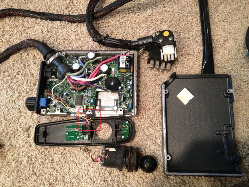
I'm using a Pride Power Wheelchair Jet 2. I've pried apart the controller - the joystick is connected with a 6-pin connector. I've cut the joystick off - although it worked, it was bent and hard to use. Below in the photo I've red box'ed the cut ends. By process of elimination I believe the red and black wires on the 6-pin are power to the joystick PCB, so I have left those disconnected. That leaves 4 wires, which should be right motor +, right motor - , left motor +, left motor -.
I tried connecting each of the 4 wires to the signal pins D0, D1, D2, D3 of the EZ-B and attempted to send a signal to operate the motors, but nothing I tried worked. I tried EZB Controls for HBridge Movement, Modified Servo, Horizontal Servo, HBridge and servo speed. Anyone have any ideas? I'm totally new with the EZ-B software so I'm sure I'm doing something wrong. On the HBridge Movement I tried every combination for the 4 signals.
My original plan was to use a Sabertooth 2x25 - I have it in hand, but this would be so much cooler (easier) if it worked!


I've programmed the PWM's according to the chart I reverse-engineered, but nothing moves. I've tested that the setting produced the desired voltage, but I'm wondering if there is something "special" about the joystick PCB that will prevent me from doing this. @Putt Putt might be right.
Yeah sorry, all that analog stuff was an assumption on my part. I'm guessing that there is some sort of proprietary communication like @putt putt said as they probably don't want people to easily hack the controls that some people rely on everyday. Too bad.
If you were up for the challenge you could always get a logic analyzer (Bus Pirate or Saleae) and crack the code if you were dead set on doing it and then use an EZ-Script to bitbang the protocol out. Another option is finding where the control signals go into the Motor controllers and connect into it at that point.
I've been studying up on Bus Pirate and Saleae. I have a general idea from the video here that bus pirate could give me a way to communicate with the controller. I'm not sure how I would send the serial commands to the chair controller yet.
Sorry @kbb0118 I just meant that you could use the Bus pirate as a logic analyzer and then just emulate the signal you see with it by sending out bit banged bits (highs and lows matched to the signal) with an ez-script. You may be able to use SendSerial() commands from an EZ-Script if you can figure out the baud rate and if it is indeed serial or not.
I tried the same thing. Like others here, I gave up and bought a Sabertooth. Before I did that though, I fried the joystick, and replaced it. This is a picture of the specs from the joystick.
Here is what I learned. The green wire supplies a constant voltage. The blue and yellow need to provide that same voltage in the neutral position. When voltage from either of those goes up or down, it moves the chair in either the X or Y direction.
If the chair senses anything that it perceives as funky, you get an error message and the system shuts down.
Good luck. I hope that this helps.
Edit: The picture uploaded smaller than I created it. If you cannot read it, I have a PDF file that I can email you.
@Danger that is awesome - Your diagram gave me a few ah-ha's! My joystick is similar, but not exactly the same. Some of the principles of movement appear to be the same as your joystick. Mine is a double decoded contactless inductive 5V joystick gimbal. I FINALLY found some good docs on my controller! I've emailed Rosstron to see if they will give me the spec sheet for my joystick gimbal DLGSM55122.
I found some students at UC Berkeley succeeded in communicating with my exact Jet 2 controller - Dynamic DL 5.2i (DL50UBR12) - with an Uno in 2011. But they didn't document much about the RC Filter. Apparently the thing I need is an RC Filter with 9.1M Ohm resistor and capacitor value of 10uF. This allows the coupling voltage from the joystick to rise and fall gradually as I understand it. I wish they had a better photo of the RC Filter and components.
https://voidsetuploop.wordpress.com
If someone can double check my thinking on this: I'll set D0, D1, D5, D6 to be PWM based on this chart I reverse-engineered.
Their RC Filter photo
I need to know if these watt/volt resistors and capacitors will work? EZB-D0 > 9.1M Ohm 1/2W Resistor > 4x5mm 10uF 25V Aluminum Electrolytic Capacitor > WHITE wire on DL controller EZB-D1 > 9.1M Ohm 1/2W Resistor > 4x5mm 10uF 25V Aluminum Electrolytic Capacitor > BLUE wire on DL controller EZB-D5 > 9.1M Ohm 1/2W Resistor > 4x5mm 10uF 25V Aluminum Electrolytic Capacitor > BROWN wire on DL controller EZB-D6 > 9.1M Ohm 1/2W Resistor > 4x5mm 10uF 25V Aluminum Electrolytic Capacitor > YELLOW wire on DL controller
My machine was a Jet 3. The joystick sounds quite similar, except mine ran on higher voltage (8v to 14v). The problem was the failsafe. Every time I would mess with it, an error message would flash, and it would shut down. I just decided to take the easy way out and buy the Sabertooth.
But anyway, I am glad that my picture was able to help you. Your follow-up questions are way above my pay grade. I can't help you with any of that. Good luck though, I am sure that someone here can answer them. I hope that it works for you. That would make a really smooth running robot.
I'm with you @Danger being a bit out of my element on this one. I've wanted to figure out breadboarding, and apparently a RC Filter is a "simple" one to start with. I don't get the breadboard thing though. Time to find a tutorial and order some stuff!