
kbb0118
Power Wheelchair Joystick Interface To Ez-B
Hi all! I'm new here I've been lurking for some time as I assembled equipment. My plan is inspired by DJ's snow shovel bot and Ampdroid and a few others.
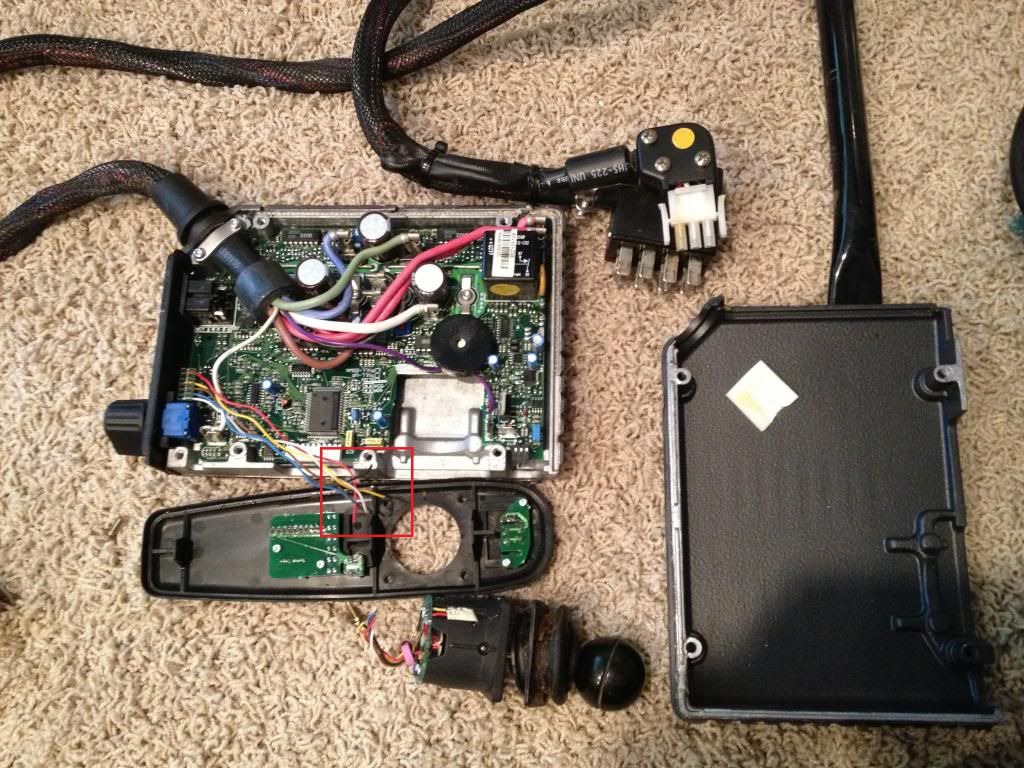
I'm using a Pride Power Wheelchair Jet 2. I've pried apart the controller - the joystick is connected with a 6-pin connector. I've cut the joystick off - although it worked, it was bent and hard to use. Below in the photo I've red box'ed the cut ends. By process of elimination I believe the red and black wires on the 6-pin are power to the joystick PCB, so I have left those disconnected. That leaves 4 wires, which should be right motor +, right motor - , left motor +, left motor -.
I tried connecting each of the 4 wires to the signal pins D0, D1, D2, D3 of the EZ-B and attempted to send a signal to operate the motors, but nothing I tried worked. I tried EZB Controls for HBridge Movement, Modified Servo, Horizontal Servo, HBridge and servo speed. Anyone have any ideas? I'm totally new with the EZ-B software so I'm sure I'm doing something wrong. On the HBridge Movement I tried every combination for the 4 signals.
My original plan was to use a Sabertooth 2x25 - I have it in hand, but this would be so much cooler (easier) if it worked!


Still waiting for my half breadboard, capacitors and resistors, Bus Pirate and whatnot. I did hear back from Rosstron pretty quick! Joystick electrical specs are:
Red +5V Supply Black zero V Supply All neutrals within 40mV of 1/2 Supply
Blue Left/Right 2v5 +/- 1V White Left/Right Inverse Mirror 2v5 +/- 1V
Yellow Forward/Reverse 2v5 +/- 1V Brown Forward/Reverse Inverse Mirror 2v5 +/- 1V
So it looks like that matches what saw in PWM voltages pretty close. Once I filter the PWM with a low pass filter hopefully this thing will move! I will update as soon as I get my parts and try things out!
Hi kbb0118,
So just wondering if you had any success on controlling the wheelchair. I seem to only be able to control it to go forwards but not any other direction.
Cheers!
I've made the breadboard low-pass filter and am attempting some tests. I'd really appreciate if someone could look it over and tell me if I've done anything wrong? Grounding and whatnot. This is my 1st breadboard
Overview
Angled view
Breadboard closeup low-pass filter
The male 4-pin I am planning to hook to the wheelchair controller as soon as I'm sure I won't fry anything with this getup
From the looks of it, it seems exactly the same as I have done. I'm assuming that the green wire will go to ground? If so, that should be correct.
If I may ask, what resistor and capacitor values have you used? I've used 160k and 1uF and I think this may or may not be the problem that I'm having.
@justindra I tried to match the UC Berkeley team's calculations (see link in post #15) since they were using the exact same wheelchair base as I am. It is hard to tell exactly what they used as they didn't document their low pass filter much.
I'm using: 9.1M Ohm 1/2W Resistor 4x5mm 10uF 25V Aluminum Electrolytic Capacitor
I'm going to try to connect it tonight!
Well, so far it has not worked. The unit does not do the "something's wrong" blinking lights, but it also doesn't move. It may require that the joystick be actually plugged in, or possibly I have to join the joystick to the low pass filter.
It will take some time to figure this out so I'm going to mark this thread as answered. Thanks for the help everyone! I'll post here if I figure it out.
I'm trying to make a remote control lawnmower to cut this steep bank I have in the yard. I bought a used power wheelchair that uses a 6 wire joystick controller, a Dynamic DL5.2i. Using slide pots and servos I couldn't get the full span using either the controller power or an remote battery, but it did work and was stable. So I went to using an Arduino Uno board. The program is basically scaling and creating the 4 signals (fwd/rev, lft/rht and the mirrors of these signals) to emulate the joystick. The 4 outputs are connected to the controller through low pass filters using 4.7 k ohm resistors and 1 uf capacitors. Those are the only connections to the controller. The controller is completely floating, no grounds or 5 volts, just the 4 output signals from the Arduino board. This setup is working very well. I get the full range to the controller and it seems to be stable. All is working well, at least for the 2 weeks it's been together. I think the key to this setup is the capacitors. I used some 25 volt aluminum electrolytics and it did not work. I switched to a CDE WMF 05W1 (1 uf 50 VDC) and it worked. I removed the ground from the caps but left them connected together and it is even more stable. Also, take voltage readings of the four inputs on the joystick connector with nothing connected but powered up. Mine was around 2.48 volts. Get as close to this as you can with the Arduino board, the closer, the more stable it is at rest. I also created a deadband around 2.5 volts so that it always comes back to the 2.48 volts in case there is any drift from anywhere. Another thought, I actually have the CDEs connected backwards, black band to the high side. Don't know if this makes any difference or not. I also think that since the low side of the caps are no longer connected to ground that a regular AC cap would work as well. Maybe it just has to be a film cap not metal.
No disrespect intended but...... perhaps there are some here that can help but maybe you should head over to the Arduino forums for more informed help. If you were using an EZB board these drawbacks would be simpler to overcome and you could get more answers to your problems here. Good luck, wish I could help. Sounds like you have a very cool and useful robot there.