Netherlands
Asked — Edited

Ping Navigation Plugin

Hey everyone,

For the last 4 weeks I've been working on my own navigation plugin, that uses ping sensors for it's distance sensing and I ran in to a few problems... Mainly that I'm not a very good programmer... Last time I made a program was in college and that was still in visual studio 2006... and about 2 years ago... But I started with full conviction and dedication that with the power of the internet everything is possible. And so far I find it kind of addictive eek ...

The Goal The goal of this project is to make a plugin that makes my robot and other robots semi autonomous in their navigation. The idea is to have a window with a picture of a robot in the middle and where you click it will go to, both on the screen and in reallife.

The robot will use atleast 5 ping sensors on the front, a Kangaroo for positioning and a compass for determining the direction. Also I will use an arduino to read out the ping sensors and possible others aswell. It reduces the amount of ports required on the EZ-B by a lot.

Short term goals Making all base functions work. By this I mean:

  • Drive controls: steering, backward & forwards, position & speed control.
  • Reading out sensors: ping sensors, compass.
  • More pretty gui features.

Long term goals

  • Static object avoidance.
  • Applying a tangent bug algorithm for navigation or similar.

When it works Goals

  • GPS for outdoors.
  • Mapping(possibly a sharp IR sensor that scans).

Current state So far I've been working on a config panel in which one can add all the required data and test features on the robot. This is both for testing and for me to learn how to make each feature so I can I apply that later on in the project.

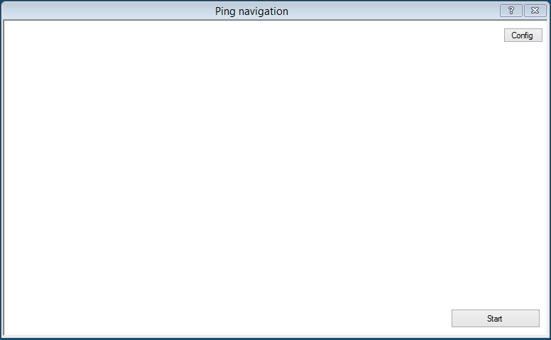
Some images: Mainform User-inserted image

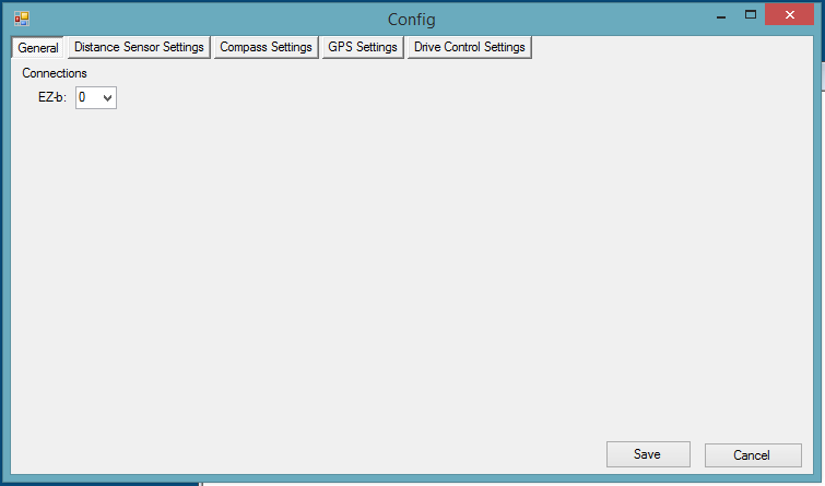
Config General Settings: User-inserted image

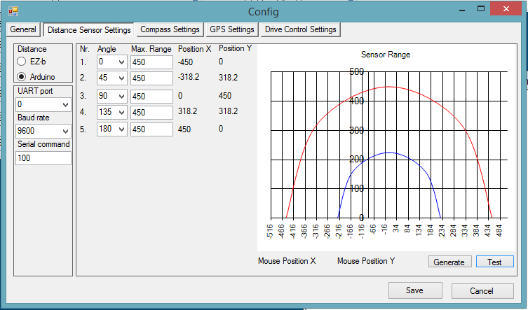
Config Distance Sensor settings: User-inserted image

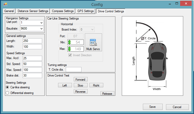
Config Drive control settings: User-inserted image

So what's working so far...

  • It remembers stuff... So all variables are saved and loaded.
  • It calculates positions based on set angles and set max range.
  • It controls servo's.

My current issue: I have not been able to get the UART working... It does nothing... I have no idea what the problem is. I tried reverse engineering it from the EZ-SDK and the Dynamixel plugin that DJ made without any luck. I usually get a long way with a clear example, those got me so far my entire plugin.

I want to use the UART to control the kangaroo and the arduino. For the kangaroo I need to:

  • Initialize the baudrate at 9600.
  • Initialize the motors by sending: "1, Start, 0x0d" and with a delay(250ms works) "2, start, 0x0d".
  • Set the motor speed by sending: "1, s-30, 0x0d" and with the same delay "2, s-30, 0x0d".

It's a work in progress, any help would be much appriciated, I will upload it once I complete the long term goals.

Also a many thank you's out to DJ and CochranRobotics for their plugins without I would have probably ran a ground way sooner :D


ARC Pro

Upgrade to ARC Pro

ARC Pro is more than a tool; it's a creative playground for robot enthusiasts, where you can turn your wildest ideas into reality.

PRO
Synthiam
#1  

This is great :)

Are you using the UART on the ez-b or the PC?

Netherlands
#2  

I'm using it on the ez-b.

#3  

This seems really cool.... I hope you finish it and get it working... :)

#4  

Hey, this looks really cool. Good job.

On the uart, I am sorry but I don't do things this way. I don't use the uart from the EZ-B but do use an onboard computer with a USB-TTL device that communicates to the Kangaroo and the Arduino's that I have in my project. I have used the uart through ARC though.

Have you tried your commands through ARC SendSerial command to make sure that they are correct?

Netherlands
#5  

@CochranRobotics It works fine through ARC, before I started with this plugin I made a movement script panel and had full control. So I know it works, so it's definitly what I've tried so far with uart... With the EZ-Script I know what code I need to set it up, but in C# I don't have a clue...

I understand, unfortunately I don't have the space nor the weight capacity to carry an onboard computer. I would love to put a lidar on top, it adds atleast 10 awesomeness points :D.

Netherlands
#6  

So after about 2 weeks of trying to make it work I had a special moment when I realized what the problem was... The serial commands weren't being received as what they were send. I felt quite stupid after finding the solution... 1 line of code fixed everything... It was way simpler than I thought it was... But everything works now. I now have full control over the Kangaroo through my plugin which is fantastic.

So... Of to the next problem.

PRO
Synthiam
#7  

Great news for Friday:) congrats!

Netherlands
#8  

I have been making some great progress with the plugin:

  • Acceleration/decceleration has been applied to the kangroo test controls. So the robot will accelerate/deccelerate with the specified acceleration up to the specified speed.

  • The test controls show realtime drive speed from the kangaroo. User-inserted image

  • Communication with the arduino has been established. The distance panel will show the actual distance measured by the arduino received by the EZ-B and it will be displayed in the graph.

Today I also received my compass, well its a 10 DOF IMU from Adafruit. I though it would be fancy to have some extra features like pitch & roll angle, altitude and temperture.

Using some quick coppy&pasting action from the examples combined with my own arduino sketch and I can now access all data from the IMU aswell. I expected to have more problems but it works. I only need to add this to the plugin. I'm imagining cockpit like gui for the compass tab in the config :D

User-inserted image

I'd say great progess, especially if I think about 4 weeks ago when I was still scratching, my head over variables and forms :P. Once I complete the gui for the compass and other sensors I should be able to start with the actual navigation :D

Netherlands
#9  

Time for another progress update. I finished making the GUI for the config tab for the Compass/10DOF imu.

User-inserted image

Added features for calibration, corrections and sorts. It also works, which is quite important :P. So far communication works fine through the arduino. However I did notice that the response time increases if one of the sensors isn't connected to the arduino.

On this note I've completed all my short term goals: Full control over the Kangaroo:

  • Setting the speed of either motor.
  • Getting the speed.
  • Setting the travel distance.
  • Getting the traveled distance. Completed the communication with the arduino:
  • To read out all distance sensors.
  • To read out the compass heading. Added some extra features that came with the 10DOF IMU:
  • Pitch.
  • Roll.
  • Altitude (relative ofcourse, due to it reading the air pressure.)
  • Temperture (also relative due to the IMU heating up after using it for a while).

So overall good stuff. Next part of the project will be making the actual navigation part. My idea was to use a "tangent bug" algorithm to do the route planning. I have yet to get idea on how thats going to work. Reading papers about it only confuses me furter, so I found this diagram, which seems to portray what I want to achieve:

User-inserted image

It seems to be the logical path to follow, so to be continued.

PRO
Synthiam
#10  

Great work! I'm impressed

Netherlands
#11  

Another week, another achievement. Last week I started working on the mainform, adding it's first features required for navigation. I made a panel which will be used to display and plot a route for the robot to follow. By clicking on various places inside the panel it will generate waypoints and connect these by lines. It has no other function that to show the user the order and planned route. In reality it would only need the x/y coordinates which are stored in a list :D. The first waypoint will be the start, the second and third, etc. will be the destination.

I also added a panel which offers the user the ability to select waypoints and see it's coordinates inside the panel. The coordinates are based on a graph where the middle of the panel is x=0/y=0 and every pixel counts as 1cm or 1 inch depending on the values given by the distance sensors. Ofcourse I took it into account that sometimes a larger field might be required, so I added a scaling feature to it in the config.

User-inserted image

I have had some issues getting this to work. My biggest issue was storing the previous line drawn... The new one would remove the old one >.<. In the end I found out that my approach was wrong and I followed a different one which did work out and was way, way easier.

Next on my lists are more features for the waypoints. Removing and adding waypoints. Displaying something that looks like a robot and displays real time information. Displaying the object resembling the robot with a heading relative to the north inside the panel and possibly sensor distances.

For the sensors I'm thinking half shaped circles growing in size the further the are. relative to a 30 degree angle from the robot. As most ping sensors have a 30 degree spread. So these circles will be projected inside the panel relative to the position of the robot, sort of making a map. Very low resolution ofcourse.

So far I'm getting closer and closer to the navigation part :D.

Netherlands
#12  

"Small" update on this project: I've been working on and off on this part of my robot project. So far it's a great learning experiance. Just whish I had more time. Anyways, I've made the first start of the object avoidance part of this plugin and it's working which is fantastic. It will now, based on sensor readings stear or reverse away from objects.

It's still quite slow, but it's a start.

My next goal will be to speed it up, get faster response time and add compass data so it'll stear around and object and will continue on it's route.

#13  

This is looking really good. I look forward to watching your progress.

Alan

#14  

That's great. Writing a plugin for this is an awesome idea. Very impressive and it must be a lot of work. I really wish I knew how to write the type of code needed to make one. Sounds like I need to add this to my bucket list.

Ya, not having enough time for things we like to do really does suck. I understand. It's one of my main gripes in life. :( However, it does help me to appreciate the time I do have and if this is my biggest problem in life I guess I'm doing pretty good. :)

Nice work so far and I'm enjoying watching your build. I love the way you've worked through each step and problem. Thanks for sharing your progress. Please keep it coming. It's very inspiring. :)

Netherlands
#15  

So after careful consideration and lots of testing, I've decided to make a major change to this project.

As it's currently configured, for the project you basically have the EZ-B as main controller, which controls:

  • The kangaroo x2
  • An Arduino which controls 5 pings sensors & 10DOF IMU
  • 2 Servo's for steering

But I've ran in to a few problems and noticed that I cannot achieve faster response times between, the Arduino to the EZ-B to pc where the distance measurement data is processed, after which a reaction is made and send back to the EZ-b, e.g. an object is in the way and it should steer away.

Now the problem is that the distance sensors don't read far enough distances that I can plan a head and avoid objects in time. It's also my goal to make my robot fast which requires an even larger measuring distance en furter a head planning or faster reads from the sensors.

To Solve this problem I've deciced that the cheapest option is to stick with my current sensors and increase the read out speed. Due to the communication to the place where the data is being processed being to slow and quite far away so the solution I've come up with is to decrease the "distance" between reading out the sensors and the place where the data is processed. So I've decided to move that part to the arduino reading out the sensors. So all controls and navigation regarding will be processed and executed by the arduino so the whole loop gets significantly reduced in length. Which should result in way way faster response times.

So what does this mean? Well I'm going to rewrite a large portion if not most of my plugin and arduino code. Most of the code is based around settings, testing and controlling the individual components, i.e. kangaroo, serial ports, servo's. All of that will be moved to the arduino. The same will happen for the actual object avoidance part of the code, which so far supprisingly enough is only like 10-20 lines code.

Where does the EZ-B come in now? The EZ-B will still be important, as it will tell the arduino what to do. At first it will give a heading and a distance to traverse, with plans for gps on the arduino. So the EZ-B will send GPS coördinates.

So for now I'm waiting for a shield for my arduino mega 2560, so I can switch out the arduino nano I'm currently using. I've already rewriten a large portion of the code for the arduino, drive controls for the kangaroo, servo's, ping sensors and the 10DOF IMU. I've also tested the first few parts with good results. Once I've switched out the arduino and rewired my robot I can test more features of the code after which I'll start reworking the plugin.

The plugin will still have features where one can test the individual functions and ofcourse plot routes and start/stop it.

So yea, lots to do and much to think about.

If anyone would find it usefull, I can post my current plugin so parts of the code can be used for other plugins or C# programs.

Portugal
#16  

Why dont you use the ping sensors directly in the EZB. I have my robot navigating with 3 ping sensors and they respond instantly. Why use arduino for this?

Netherlands
#17  

Well, the main reason is speed & costs. I want to make my robot travel at, atleast 20km/h (prefferably more)and keep the costs low(better sensors cost more). So if we add some math to this idea and the sensors I'm using, the following comes up:

Desired speed: 20km/h = 5.56m/s. Max range of the pings = 4.5m. Number of sensors I'm using = 5. (having one or more that turns to read at different angles would not be fast enough). Max read speed, about 100ms (via EZ-B) per sensor to prevent channel flooding.

Time to read out all sensors: 5 * 100ms = 500ms = 0.5s

Distance traveled within reading time: 5.56 * 0.5 = 2.78m

So this means that my robot will have travelled almost 3 meters before the next reading. And this is asuming these sensors dont give false readings. This is also without taking other processes in to account. E.g. reading out compass, controlling servo's/kangaroo, etc.

Now with an arduino, I can do the same, but the read outs are much faster as I don't have to keep in mind any channel that will be flooded. It can read out a ping sensor every 29ms(faster would cause interferrance between sensors). And don't have any delays with processing the sensor results(from EZ-B to pc and back). Meaning with 5 sensors the max read time would be 145ms. Making the distance traveled within reading time is about 0.8 meters thus leaving more time for other tasks.

It's pretty much the same reason as to why you should always keep 2 seconds of distance while driving a car between you and the car in front of you. If your sensors (your eyes) notice that the car in front of you brakes suddenly then on avarage it would take your EZ-B (nerves) and pc(brain) about 1 second to notice and react other second to brake.

My last reason is because I can and learn from it.

Portugal
#18  

That is very fast robot. So what you are saying is that the data from the ping sensors is not sent to EZB and that the arduino controls the motors. If that is the case then you are right, its faster. I saw your video and the reaction time of the motors is very slow. As i said, i have my sensors wired to the EZB and the reaction is instant. So i wonder what is causing that delay. Regards.

#19  

Sounds like a very cleaver and needed change. Nice thought process. It's fortunate you're talented in writing the needed code to do all this.

Netherlands
#20  

@Proteusy Thats exactly what I'm going for.

As for the delay, I can't get a faster response time between Pc > EZ-B > Arduino and back than 1000~1100ms. My first solution was to have the Arduino read out the pings and relay that to the EZ-B which didn't help. So now I'm going to try it this way.

@Dave Thank you for the complement. But it's more like a lot of elbow grease rather than talent :D. When ever I try to make something, I split it up into small steps, so I can focus on smaller problems and not get blinded by the whole.

For example for this project I want to achieve object avoidance and navigation. Thinking about it, just like it is, I would have no idea where to start, but if you "zoom" in further and think about it in smaller parts you can make a list of on what you need to achieve this goal:

  • Reading ping sensors
  • Controlling kangaroo X2 via serial
  • Controlling servo's
  • Splitting up serial data into separate variables
  • etc.

Once I have a list either in my mind or actually on paper I start at the top. First I need my robot to know when something is in the way, so I started searching on how to achieve this, starting with 1 sensor. Once I found out for the first one I started looking on how to add more and reverse engineer it to my own needs.

Second step I made was motor control, from experience with the EZ-B I already knew I would need serial commands to control the Kangaroo X2, so I started looking for a way to send and read serial commands and reverse engineer that aswell to my needs. i.e. making loops for Accelerating, decellerating and stopping.

etc.

I try to apply this to every small part which together make this project, step by step, problem after problem and test after test. I try to make a part of the code every week or every few weeks and hopefully when I get to the end it works. If it doesn't I'll look for a different approach.

Netherlands
#21  

I finished rewiring my robot to have all movement controlled by an arduino mega. I also finished the first part of the firmware for the arduino. It now does basic object avoidance, based on objects in front or on the sides.

Static test:

Freeroam test:

So far so good. Next up is adding compass to the navigation system. And reworking the plugin to also include robot control with arduino only.

Portugal
#22  

That does not seem to be 20km/h or faster. Also the turn angle is very low.

Netherlands
#23  

@Proteusy If I drive something... It doesn't even matter what... With 20km/h in my house, if something goes wrong, I will have to scrape whatever is going 20km/h from whatever it crashed in to. As this was one of it's very first tests on the ground to drive at higher speeds indoors would be dangerous and irresponsable. Besides it being unsafe, with 20 km/h it would cross my living room in 2-3 seconds, so there's not even a point in trying.

This was just one of my first tests after rewriting the code for the arduino... It took me 2 weeks to get it working without a hitch and I thought I would share it. So far it drives forwards until it finds something, then it'll either stear away or backup and then stear away after which it will continue on it's marry way until it finds something else.

If I were to test my robot at full speed it will either be a static test, where my robot will stand on blocks, or outside, which will not happen until I can command the arduino with the EZ-B and I'm confident it will function propperly.

#24  

@ budel0, you have come a long way and it looks real great. I look forward to more videos and hope that you might share with the community when finished.

Nice work.

#25  

This is undeniably a very smooth, quick and nicely working avoidance system. I really like the quick responce and the way it maneuvers it's self back into the open.

Am I right to assume that you've totally removed the EZB from the navigation part of this system and given it all over to the arduino mega using your code? Getting that code right and working on it for that long must have been mind numbing. However I'm sure you have a huge satisfaction factor. I'm amazed at what people with your coding skills can do. I wish I had the time and ambition to learn coding to your level. Nice work! ;)

Netherlands
#26  

merne Thank you for your nice comment, the goal is to improve it and add more features to the arduino and my plugin. Once it's been completed or if requested I can share what I made. I'm trying to make my plugin as "neutral" as possible so others have a use for it aswell, however I will first make everything so it works for me and then I'll expand on it and make it work for others. The arduino part can be modified to fit every robot.

Dave Thank you for the kind complements :D. You guessed it right, I moved all of the robot controlls (kangaroo & servo's) and sensors(ping & compass) to the arduino. The communication over wifi made the processing too slow and the best way to increase the speed was to take out the wifi and process it locally, making it about 40 times faster :D.

However it was rather frustrating getting the object avoidance to work... It used to have this problem if you would block the front and either one of the sides that it would crash the arduino, causing it to drive back and forth while constantly turning left and right... But the problem was that I based the object avoidance on objects being on either the left or right side instead of basing it on objects in front of it. Once I based it on that it worked like a charm with out crashing :D.

My current hurdle is the compass part. I want to have to possibility to send a heading and make it navigate towards that heading while avoiding obstacles. This way I could use the EZ-B to send the heading(maybe in the future coördinates) to the arduino from the pc and also control it manually. But as it was yesterday it kept on driving in circles... And it wouldn't stop going in circles :P. But I'll solve it at some point, one step at a time.

Netherlands
#27  

Another week another succes with the programming. I managed to combine obstacle avoidance with compass navigation. Now it's possible to set a certain heading and the robot will stear towards that heading within 1 degree accuracy. It can be placed towards any angle and it will correct autonomously to the set heading. While this is happening it will also check if there are no objects in it's way. If it finds an object it will disable the compass course corrections until it passed the objects that are in it's way. After which it will enable it again and return to the set heading.

The next step in this project will be reworking the plugin to include controlls which are used when all robot controlls are controlled by the arduino.

#28  

Sweet! :) You guys up north are truly geniuses. So much cool and stuff coming from the Netherlands and Canada. Must be all that cold weather.

Netherlands
#29  

So instead of doing what I said I was going to do I kind of did it, but did something compleetly different aswell... I made the foundation in the plug in where you can select a radiobutton to control the general robot controls via arduino, it doesn't do much more. I'll continue with that later, what I instead did was I scored myself an Adafruit GPS Ultimate v3 breakout board. Which is a GPS receiver.

For the last 4 days I've been playing around with it, got it working on an Arduino UNO, but then... The struggle began... What ever I tried I could not get it to work on the Arduino Mega 2560 thats currently in my robot... It wouldn't return anything no time, no latitude, no longitude... Not even NMEA sentences... Which was really frustrating... And even worse the solution was ridiculously simple... As always... I had to change one word and two signs in the sample code and it worked... Took me 5 days to find which ones but it works!

User-inserted image

So what does this mean, well after reverse enginering the sample code in to the code for the robot I can now request it's GPS position. This means that once I've figured out how, you'll be able to send waypoints and the robot will navigate there, combined with obstacle avoidance. My main reason for adding something like GPS is that it makes it easier to go from A to B with objects in between.

Going from point A to point B in a straight line is easy, set out a heading and the distance that needs to be coverd and you're set. However once an object is detected the robot will have to navigate around it, but continuing behind the object in the exact heading and spot compared to where you started navigating around it is very very hard. Its not impossible, but to achieve that you will need accurate motors, accurate encoders and a very good system which keeps track of the changes in position and actions so the robot will end up in the right spot. Because keep in mind your robot doesn't know where it is in this case. It only knows it's heading, the distance it needs to travel and if there's something in front of it.

By adding GPS, the robot will know where it is, knowing its destination and its own position, it will know what actions are required to reach its destination. It won't be accurate, the box says 1.8m radius(still quite accurate, for it's price) but 1.8m is still more accurate than nothing.

Next step is to make a system which stores waypoints and a system which calculates the heading based on latitude and longitude. The last one will be the hardest as it requires a lot of math, based on the curvature of the Earth and geometry. (Geometry wasn't my strongest course in school, give me algebra any day :D)

Netherlands
#30  

Time for a small project update. Since I got the GPS module working I've managed to find the correct formula's to calculate the bearing and distance between two GPS positions. I combined this with the compass course correction code I made earlier and started a 4 week long period of testing.

Lets just say it was a very frustrating 4 weeks in which I only yesterday at 2 am fixed the last problem... The main problems I had were that the robot wasn't driving in the correct direction...

The first problem was that certain sequences in the code were wrong, which didn't take too long to find each of these. My biggest problem was that the compass I was using didn't give the correct heading, mainly caused by not being calibrated and Adafruit the manufacturer not giving support on how to calibrate it... In the end I fixed it by using the libraries from Pololu...

The last problem was that the calculated heading was off by 360 degrees... Which is a rather interessting problem... Eg. the actual heading is 50 degrees, but it will calculate 310 degrees... With a simple tweek that problem was solved.

And finally today I could place my robot on the ground, set a gps position and it would go there and then stop at the set position. Which is great.

But it's not perfect yet. I have found new problems:

  • The compass is getting EMI, when the motor's are running the compass heading fluctuates ±40 degrees... It gets to the desired location, but not very smoothly.
  • Object avoidance: the real world is harder to evade that my living room... The robot got stuck in a lot of corners were it ended up going back and forth until I turned it off...

But in conclusion of this short update it works:

  • Object avoidance, it works but corners are hard.
  • Compass navigation, flawless. It changes course based on compass data, though the actual compass needs some attention, to remove/reduce the interferrence.
  • GPS navigation, as planned. It calculates the heading and distance between two GPS coordinates within 0.5% and navigates to the calculated position within 1 meter. (Higher accuracy would require a beter GPS receiver with ground station and way way way way complexer formula's to calculate the data based on the Earth not
    being a perfect ball, then you can calculate up to 1 nanometer accuracy with a fixed referance. In short too much work and not necessary.)

Next goal will be to compensate or reduce the interferrence on the compass and improve the object avoidance.

#31  

How fast will your robot be when fully functional? If moving greater than 1km you could switch your heading from compass to gps to eliminate the EMI issue. Other than that, shielding and distance. Maybe put the compass on a poll. You shouldn't need to move it far to dramatically reduce the emi (inverse square law).

Alan

Netherlands
#32  

@Alan The goal is to run it at about 20km/h, as for the distance, didn't really think about it. Though I am going to look into the gps compass. The only thing I dislike about the compass of the GPS is that it has a fixed update rate, which I currently set to 5Hz and the LSM303(compass module) has up to 100kHz.

But I do like the idea of a combination of the two, mostlikely the EMI will increase on higher speeds, so it might be a work around to reduce speed when using the magnetic compass and at higher speeds the gps compass. Though if the EMI actually reduces at slower speeds is something I will have to test. I will also test it at higher speeds, because it's currently running at 1/15th of the planned speed.

As for the pole, unfortunatly it's already on a pole, which is about 20cm long and I thought that would be enough. But I'm going to try and see what happens when I wrap it in aluminum foil and other search for some other EMI insulation solutions.

Netherlands
#33  

Another week and a little bit of progress.

For the last few weeks I've been looking for solutions and probable causes for the EMI that influences the compass and now I have a small list which can be usefull for anyone who wants to use a compass succesfully. 9/10 times it's a combination of problems and not just one.

- Problem 1: Motor noise, brushed motors can generate noise on their powerlines because of the brushes making contact with the stator inside the motor.

Solution 1: Apply 3x 0.1 uF ceremic capacitors on the motor, two from motor terminal to the motor casing and one between both motor terminals.(there are more variations with more or less capacitors and some with inductors).

My motors had these build in. Check if your do, otherwise the motor or the capacitors might get damaged.

- Problem 2: Electromagnetism(1), long wires between your motor controller and motor can generate a magnetic field which can distort other electronics.

Solution 1: Twist the motor wires, atleast 1 full turn every 4-5 cm.

Solution 2: Apply shielding on these wires and connect these to your ground.

The wires to my motors are quite longso, so I chose to apply shielding, it's a metal sleeving, coverd by plastic sleeving. User-inserted image It also looks rather pretty.

- Problem 2: Electromagnetism(2), the motors themselves are large electromagnets with magnets inside them.

Solution 1: Shield the motor with a metal casing and ground it.

Solution 2: Create distance between your electronics and these motors.

In my situation there's very limited space around my motors, so it was not possible to build a casing around it, I opted for solution 2 and placed my compas on a pole. I measured with an other electric compass(my watch) on what distance the motors started to influence the compass where it started to point towards the motors instead of the north. It was about 15-20cm where the field ended.

- Problem 3: Conduction(1), noise traveling from the motor, through the controller into other electronics.

Solution: Separate the motor and controller from the rest of the circuit by using a BEC and a motor controller with optical insulation. Or use separate batteries.

In my case, I do not know if the Kangaroo/sabertooth are optically insulated, however I am using a BEC and have the possibility to use separate batteries.

- Problem 4: Conduction(2), this one is only useful for those with a metal framed robots. The switching magnetic field of your motors can create small currents inside your metal frame which will cause noise.

Solution: Ground your frame.

In my case, my entire robot is made out of aluminium, except for my gear boxes, wheels and battery tray. I connected a wire from my frame to the ground.

Here's a measurement without grounding: User-inserted image

Here's a measurement with grounding: User-inserted image A huge differance.

By applying this I removed most of the noise from my system, which is good. However this did not improve my compass readings...

By doing more tests I found out that vibrations are a major player in my problem aswell. The gears in my transmission, connecting the motors to the transmission generate a lot of vibrations. The moment I disconnected the pole with my the compass attachted to it, the readings stabilized.

Now for all those wondering if all of the above was useful and how I know it was useful. Well it didn't stabilize before. I have tried to solve the problem by disconnecting the compass from frame and it would still be unstable.

To conclude this post, I have reduced, if not mostly removed the noise from my system by applying multiple solutions to different causes of noise and EMI. In the end I could not remove all EMI from my system as the motors are just magnets where the only solution in my case was to move the compass away from it. And finally there was also a mechanical influence on the compass which effected it. I'm still working on a solution.

Netherlands
#34  

So it's been a while since I posted anything on this project, been very busy, it happens. But Im still working on it when I have the time :D

In anycase, I think I managed to solve the vibration issue in my robot with a flightcontroller vibration damper and a software based filter. Which is a major milestone if it works as planned.

The issue I've been having is that the vibrations caused by the gears in the robot were causing osscilations in the compass, which would cause the measurements to vary within 50 to 100 degrees in compairison to a measurement with the motors turned off.

So I added a vibration damper and mounted the IMU to it, which reduced the osscilations within 30-40 degrees, which is a lot better than before. To get even better data I also added an exponential filter to filter the measurements. With the filter the values vary within 10-20 degrees and that's within an acceptable range.

User-inserted image [filtered],[raw] Goal: 240

Now I only need to do some outdoor testing and see if it's still swerving around while heading towards the set GPS location. If it works I'll add a video.

Arduino filter Vibration damper

While working on the vibration problem I added a few more features, mainly revolving around a SD-card module for local data storage. This gives a lot of possibilities. Namely:

  • Sensor data logging: The arduino logs the GPS position, together with compas heading and the ping sensor data. Collecting a large amount of this data could be used to make a low resolution map, based on its location, heading and distance measurements.
  • Return to home: It stores it's starting possition when it's turned on or you can set a specified starting point and command it to go there.
  • Waypoint logging/storage: Add waypoints on the fly, giving the possibility to make routes and set destinations manually.

In the future I might store all variables on the SD-card to reduce time between tests when changing certain settings and not constantly have to reflashing the arduino.