
budel0
Hey everyone,
For the last 4 weeks I've been working on my own navigation plugin, that uses ping sensors for it's distance sensing and I ran in to a few problems... Mainly that I'm not a very good programmer... Last time I made a program was in college and that was still in visual studio 2006... and about 2 years ago... But I started with full conviction and dedication that with the power of the internet everything is possible. And so far I find it kind of addictive eek ...
The Goal The goal of this project is to make a plugin that makes my robot and other robots semi autonomous in their navigation. The idea is to have a window with a picture of a robot in the middle and where you click it will go to, both on the screen and in reallife.
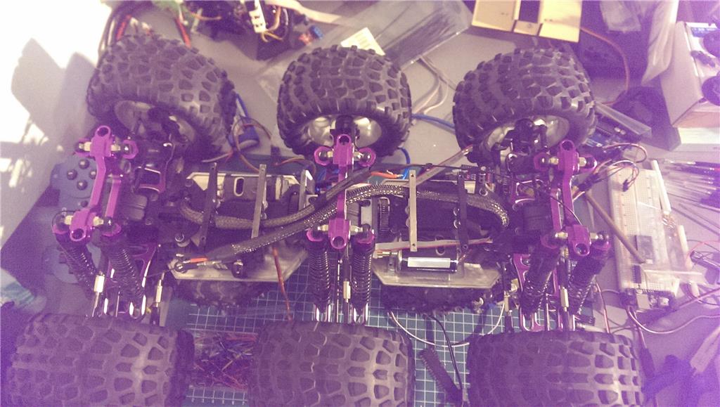
The robot will use atleast 5 ping sensors on the front, a Kangaroo for positioning and a compass for determining the direction. Also I will use an arduino to read out the ping sensors and possible others aswell. It reduces the amount of ports required on the EZ-B by a lot.
Short term goals Making all base functions work. By this I mean:
- Drive controls: steering, backward & forwards, position & speed control.
- Reading out sensors: ping sensors, compass.
- More pretty gui features.
Long term goals
- Static object avoidance.
- Applying a tangent bug algorithm for navigation or similar.
When it works Goals
- GPS for outdoors.
- Mapping(possibly a sharp IR sensor that scans).
Current state So far I've been working on a config panel in which one can add all the required data and test features on the robot. This is both for testing and for me to learn how to make each feature so I can I apply that later on in the project.
Some images: Mainform

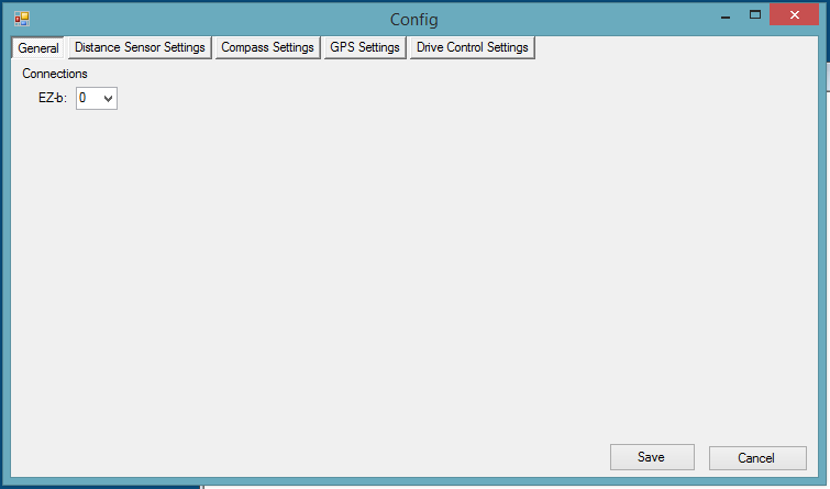
Config General Settings:
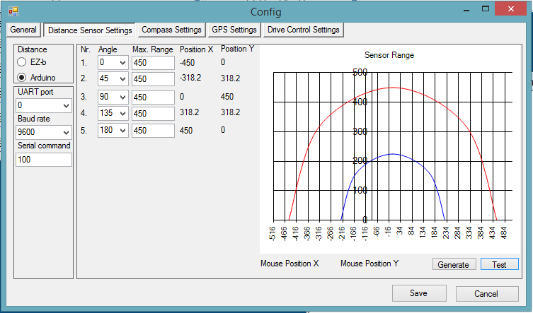
Config Distance Sensor settings:
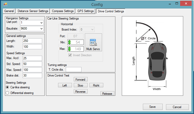
Config Drive control settings:
So what's working so far...
- It remembers stuff... So all variables are saved and loaded.
- It calculates positions based on set angles and set max range.
- It controls servo's.
My current issue: I have not been able to get the UART working... It does nothing... I have no idea what the problem is. I tried reverse engineering it from the EZ-SDK and the Dynamixel plugin that DJ made without any luck. I usually get a long way with a clear example, those got me so far my entire plugin.
I want to use the UART to control the kangaroo and the arduino. For the kangaroo I need to:
- Initialize the baudrate at 9600.
- Initialize the motors by sending: "1, Start, 0x0d" and with a delay(250ms works) "2, start, 0x0d".
- Set the motor speed by sending: "1, s-30, 0x0d" and with the same delay "2, s-30, 0x0d".
It's a work in progress, any help would be much appriciated, I will upload it once I complete the long term goals.
Also a many thank you's out to DJ and CochranRobotics for their plugins without
I would have probably ran a ground way sooner

Another week and a little bit of progress.
For the last few weeks I've been looking for solutions and probable causes for the EMI that influences the compass and now I have a small list which can be usefull for anyone who wants to use a compass succesfully. 9/10 times it's a combination of problems and not just one.
- Problem 1: Motor noise, brushed motors can generate noise on their powerlines because of the brushes making contact with the stator inside the motor.
Solution 1: Apply 3x 0.1 uF ceremic capacitors on the motor, two from motor terminal to the motor casing and one between both motor terminals.(there are more variations with more or less capacitors and some with inductors).
My motors had these build in. Check if your do, otherwise the motor or the capacitors might get damaged.
- Problem 2: Electromagnetism(1), long wires between your motor controller and motor can generate a magnetic field which can distort other electronics.
Solution 1: Twist the motor wires, atleast 1 full turn every 4-5 cm.
Solution 2: Apply shielding on these wires and connect these to your ground.
The wires to my motors are quite longso, so I chose to apply shielding, it's a metal sleeving, coverd by plastic sleeving.
It also looks rather pretty.- Problem 2: Electromagnetism(2), the motors themselves are large electromagnets with magnets inside them.
Solution 1: Shield the motor with a metal casing and ground it.
Solution 2: Create distance between your electronics and these motors.
In my situation there's very limited space around my motors, so it was not possible to build a casing around it, I opted for solution 2 and placed my compas on a pole. I measured with an other electric compass(my watch) on what distance the motors started to influence the compass where it started to point towards the motors instead of the north. It was about 15-20cm where the field ended.
- Problem 3: Conduction(1), noise traveling from the motor, through the controller into other electronics.
Solution: Separate the motor and controller from the rest of the circuit by using a BEC and a motor controller with optical insulation. Or use separate batteries.
In my case, I do not know if the Kangaroo/sabertooth are optically insulated, however I am using a BEC and have the possibility to use separate batteries.
- Problem 4: Conduction(2), this one is only useful for those with a metal framed robots. The switching magnetic field of your motors can create small currents inside your metal frame which will cause noise.
Solution: Ground your frame.
In my case, my entire robot is made out of aluminium, except for my gear boxes, wheels and battery tray. I connected a wire from my frame to the ground.
Here's a measurement without grounding:
Here's a measurement with grounding:
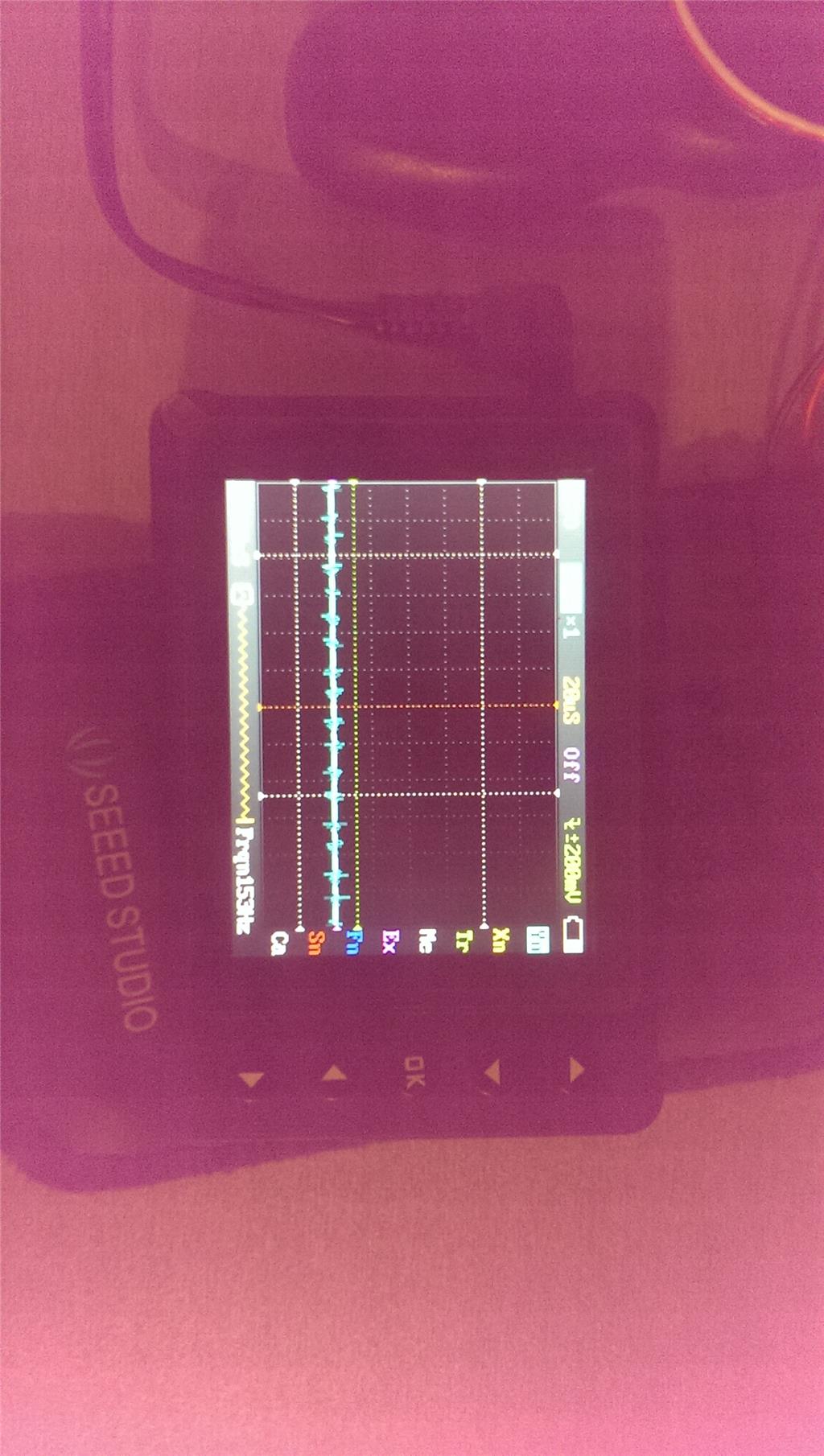
A huge differance.By applying this I removed most of the noise from my system, which is good. However this did not improve my compass readings...
By doing more tests I found out that vibrations are a major player in my problem aswell. The gears in my transmission, connecting the motors to the transmission generate a lot of vibrations. The moment I disconnected the pole with my the compass attachted to it, the readings stabilized.
Now for all those wondering if all of the above was useful and how I know it was useful. Well it didn't stabilize before. I have tried to solve the problem by disconnecting the compass from frame and it would still be unstable.
To conclude this post, I have reduced, if not mostly removed the noise from my system by applying multiple solutions to different causes of noise and EMI. In the end I could not remove all EMI from my system as the motors are just magnets where the only solution in my case was to move the compass away from it. And finally there was also a mechanical influence on the compass which effected it. I'm still working on a solution.
So it's been a while since I posted anything on this project, been very busy, it happens. But Im still working on it when I have the time
In anycase, I think I managed to solve the vibration issue in my robot with a flightcontroller vibration damper and a software based filter. Which is a major milestone if it works as planned.
The issue I've been having is that the vibrations caused by the gears in the robot were causing osscilations in the compass, which would cause the measurements to vary within 50 to 100 degrees in compairison to a measurement with the motors turned off.
So I added a vibration damper and mounted the IMU to it, which reduced the osscilations within 30-40 degrees, which is a lot better than before. To get even better data I also added an exponential filter to filter the measurements. With the filter the values vary within 10-20 degrees and that's within an acceptable range.
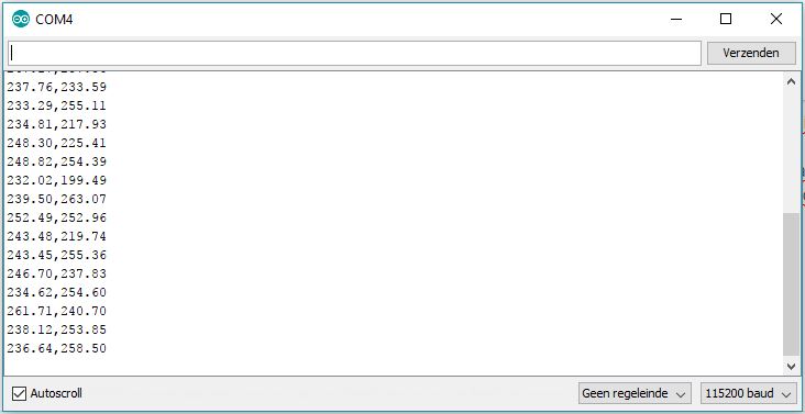
[filtered],[raw] Goal: 240Now I only need to do some outdoor testing and see if it's still swerving around while heading towards the set GPS location. If it works I'll add a video.
Arduino filter Vibration damper
While working on the vibration problem I added a few more features, mainly revolving around a SD-card module for local data storage. This gives a lot of possibilities. Namely:
In the future I might store all variables on the SD-card to reduce time between tests when changing certain settings and not constantly have to reflashing the arduino.