
rgordon
Need Ideas On Waist And Neck Rotation For Magnus
Here's the problem. Magnus will be mostly remote controlled as far as driving him around, making his arms move, waist rotation, neck rotation and such. However, certain features would be helpful if they were automated. Two such items are the neck and waist. If, for example, I rotate the waist via R/C to the right or left and then want to center it straight ahead again I want it to do this automatically. This would be more simple if I could use servos. But, I am having to use gear-motors due to his large size. I need some kind of feedback circuit or whatever....
I was thinking of maybe using an EZ-B and some type of slotted IR sensors placed at certain locations in the ARC of the waist or neck travel zone.
Any ideas for circuits, parts or mechanical stuff out there in forum land? All ideas welcome!

We need to know how these rotation joints are configured to give appropriate suggestions. Are we talking about a joint that uses a lazy-susan bearing, with the gear-motor near the outside or does it have a central axle?
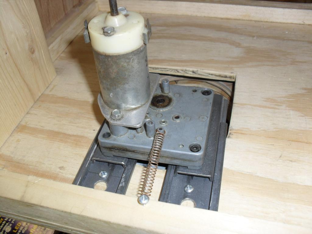
My bad. The waist joint is a large Rockler lazy-susan. It has a timing belt glued to the inner ring. A gear-motor, with a 3" cog with slots meshes with the timing belt. The motor is mounted on two pieces of drawer slide and a spring from the motor to the torso base keeps the cog against the timing belt. This lets the motor sort of float against it.
Here pictures of my smaller bot T.E.C.H. His waist is the same as Magnus except lots smaller. It is the same design with the same motor and cog and belt.
That's a great design btw.
How many teeth are on the 3" Cog & how many are on the belt? And how many degrees of rotation do you want the joint to have?
I like the lazy Susan idea with gears and motor. To have the ezb know the position isn't too tough either. Have you ever seen contact switches? There are sealed micro switches, but also open switches. If you've ever seen the inside of a pinball machine then you'd recognize them.
I'm on my iPad so I don't have a pic. But if you made raised and lowered contour cut of wood, the switch would short in different positions. That would tell your script to stop the motor.
Another idea is reed switches on a slat every 1 or 2 inches from the center out. Place a tiny magnet on the rotating part of the circle at different points that you want it to stop. As the magnet passes under the reed switch it closes. Depending on which magnet was detected will determine position. lol I think about it. That's similar to optical encoding but with magnets. But not exactly. its less accurate.
Another sensor I think I saw on ebay was a chip that is super accurate at sensing the direction of a tiny bar magnet rotating above it. You could put the magnet on the rotating part and the chip on the non rotating part. Ah ha! I found it. Ebay link
I hope that helps.
Or! Haha, such an easy and powerful solution would be to put a variable resistor in the center, or along the edge with a rubber wheel. You can determine the exactly location much like how a servo works That would be an awesome solution! You can accurately dial in any position!
The little variable resistor will turn with the body, and that adjusts the voltage to the EZ-B. Now the EZ-B knows exactly what position the robot is in.
Well, what I was trying get at with my number of teeth (ie gear ratio) question, was if attaching a 5 or 10 turn potentiometer to his 3" Cog would work or not.
Thanks everyone for the great input! I'll get back to you with the info on the cog.