
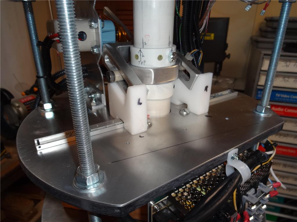
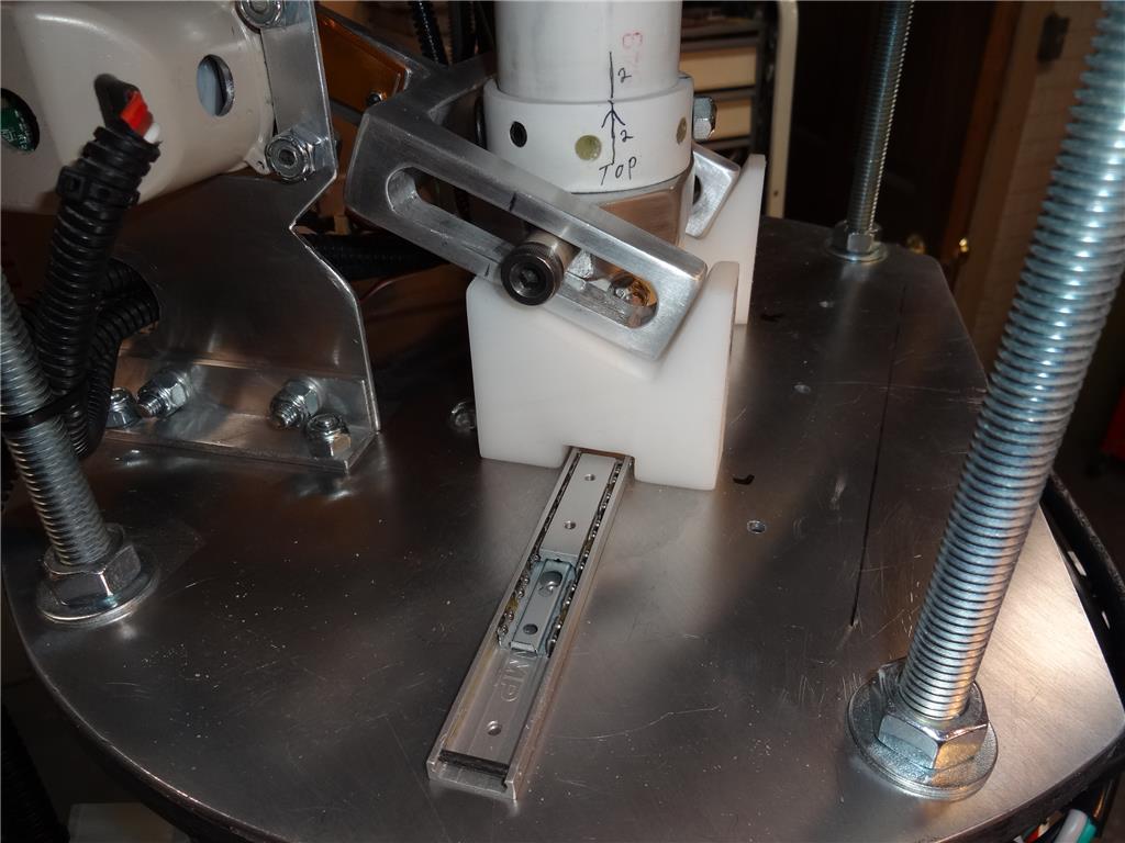
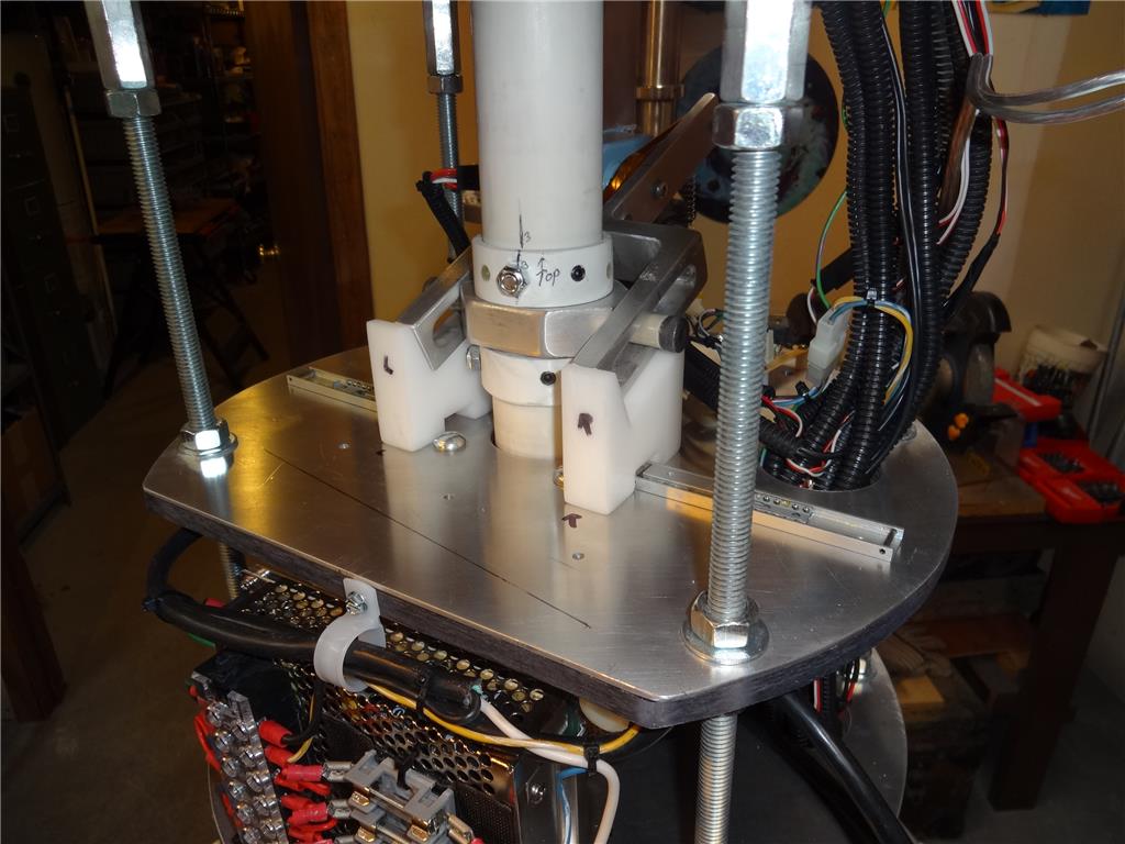
I need to find a material that will assist my bubble lifter servo lift the weight of my B9's finished bubble. It probably weighs about 5 lbs or more. Without a helper the HD servo I'm using now struggles to lift it and is slow to start moving upwards because of the weight. Up till now I've used a stiff spring as a servo helper but it was causing problems due to the way I had it attached to the lifting fork that is in turn attached to the servo and the neck pipe. The spring was attached to the front of the fork and pulling up on just one side causing binding of the neck pipe. I want to move it to the rear "handle" of the fork and perhaps make the tension adjustable somehow (adding a turnbuckle?). I also thought I'd like to use a different material other than a metal spring. Maybe a bungee cord and make it adjustable. The thing is, whatever I use I don't want the material to degrade over time or creep out of adjustment due to stretching. Does anyone have any ideas on what material I could use that would stand the abuse of wright, movement and time? I'll attach a pic or two of my present design (without any spring attached). Thanks!

Would a 12v DC motor be a better option than a HD servo because of the weight?
You could get a stainless steel hub which would bolt directly to what you need, and the motor shaft would go into that hub driving it.
Would be very quiet and uber smooth?
Could you use a large compression spring /coil that would be around the PVC tube neck tube so it would pop up better when engaged? When the bubble is down, it compresses the spring then when it lilts up it would popup? Just a thought?
Can you use 2 servos?
Do you have the new HDD servos yet.? Don't they have more power? Five pounds is a lot of weight though.
@merne mentioned a coil spring on the outside of the column. What about the inside? If you have room you can make a shaft and spring assembly, like a plunger. ? You could make it adjustable by using a threaded rod for a preload tension.
A more complex idea is a cable system with a counter-weight. Put a weight in a piece of pipe, (so it doesn't get hung up on something) in a convenient location and run a cable over pulleys, to the common ends of the fork. Add weight to give the needed counter balance. I used this in the past and had good luck with it. I could use minimal lift power to raise 250 pound covers.
By the way, I enjoyed the video, and yes I watched the WHOLE thing. LOL
It is always great to see your Buddy !
Dave, post a pic with the spring in place, please.
Could you re-locate the spring so it's at the middle of the fork tines? Run a small threaded shaft through the tines, and use nuts on the shaft to center the spring...
I was thinking something like this would be very reliable?
Thanks for all the great ideas. I've thought about each one a lot. First I need to say I'd be happy with a temp and simple solution as I really don't want to rebuild and do a lot of redesign at this time. Maybe later in the year when the snow starts flying and I have more time.
Here's what I have thought about your good ideas and suggestions and a few I had:
Use a stronger servo: Great advice but I researched the one I'm using now and It seems to be the strongest I could find at and affordable price (for me). It's a heavy duty Seiko PS050. Voltage input is between 6.0 - 8.4 VDC. I'm feeding it 7 vdc and at that voltage it's stall torque is about 1200 oz-in. doing the math that's 75 lbs-inch. Price is about 250 USD and seem to be very hard to find now.
Attach the spring to the fork more centered: Good idea and would work. Adding a spring to the center point between the forks is the proper place. However any mounting or attachment hardware would interfere or hit any already placed "stuff". A redesign would be in order. Placing the spring in the rear on the end of the "handle" would accomplish the same thing and is what my OP mentioned.
Counterbalance wright: This one really excited me when I first read it. Adding weight the rear handle would be an easy and quick way to balance out the load being lifted by the servo. The weight would help lift the load like two kids on a teeter totter. Only issue is that the weight would have to be in a sleeve to keep it from swinging back and forth when the robot rotated at the waist or leaned over. Doable. One other issue with this is it would be hard to add or remove weight to adjust the counterbalance weight.
Leverage assist: Adding an additional servo or linear actuator to assist the main servo is a possibility. Timing would be an issue as the helper servo would need to move exactly at the same as the main servo. If they are tied together they would no doubt end up fighting each other. This seems like a complicated mess and would require engineering , coding and room to keep the servos from fighting each other and burning out. Simply wiring them in tandem wouldn't guarantee exact mirror movement as all motors are different. I'd need some sort of clutch system to make up any difference.
Gearbox: Ahw... not we're talking. Use ServoCity gearboxes that are the same ones I'm using in my B9's arms to lift that heavy wrist and claw. At the 7-1 ratio I needed to lift the load I thought it would be too slow. However the seed turned out to be just fine at top speed. I don't know if the length of the arm helps to add to the illusion of speed as it swings up and down. 7-1 ratio may be to slow on the short and isolated 4" stroke of the bubble lifter. If I choose the proper servo to place in one of these gearboxes I could have more power and speed then I have now with the Seiko servo I now have. In fact I could reduce the ratio to 3:1 and still have a setup that's faster and stronger. 5:1 would probably be the sweet spot. The drawback here is I'd need to rebuild.
Scrapping the servo and using a dedicated linear actuator: Possibly the simplest solution. Trick is finding one that is speedy enough for my needs. Adding a pot for feedback of position and speed should be pretty simple. Drawback: Rebuild and redesign.
Redesign and rebuild seems inevitable, Sigh.....Truth is I've never really been happy with my bubble lifter system. Too many moving parts and it's not as smooth as I'd like.
Thanks for the advice and ideas. This really helped.
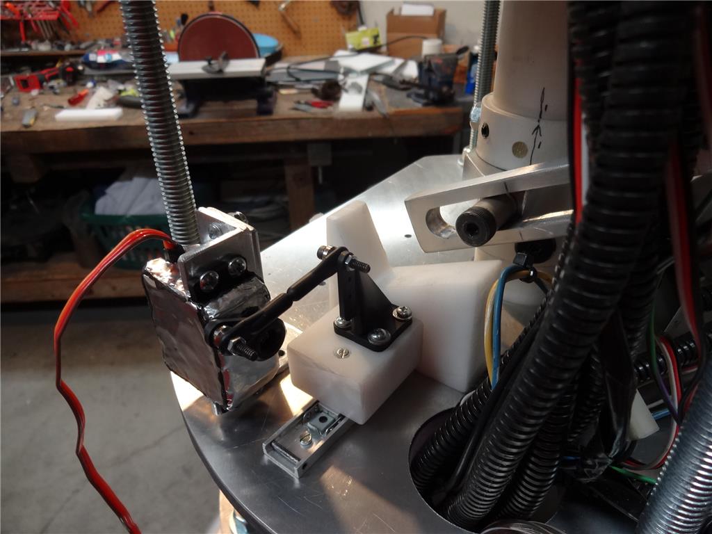
So today I've gone ahead and temporally replaced my bubble lifter servo helper. I've relocated the spring to the rear handle of the lifting fork. Actually it turned out quite well and works better than it did before when the spring was attached to the front of the lifting fork. I'd leave it like this but this design is a pain to remove and replace when I want to break down the robot and remove the torso.
I Still plan to rebuild this mech but not till I have more time towards the end of the year.
I took a little video of the final result. The thing really sucks as I couldn't really get the camera properly up inside the robot. However it's kinda fun to watch. I'll attach it below.
Thanks for all the help on this one. Dave Schulpius
Warning in advance, this video sucks. I really wasn't able to get good shots of the new mech working. However it is fun to watch so enjoy.