fredebec
France
Asked
— Edited
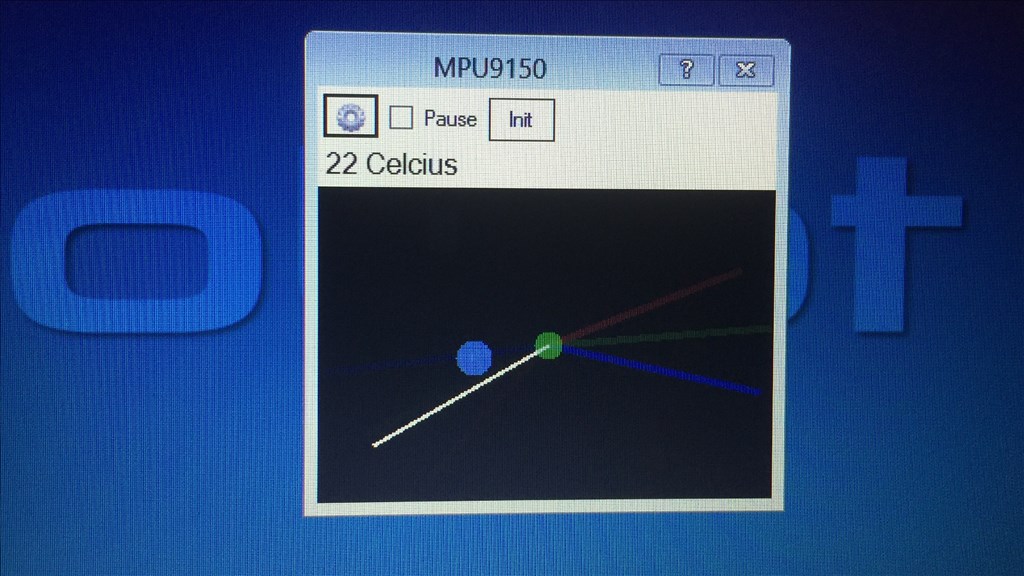
Mpu9150 - Temperature Sensor
Hi,
I have bought the MPU9150 sensor and try to use the temperature sensor. But the sensor always displays 22 Celcius, whatever the condition...
I have followed the tutorial, and Gyro and compass seem to work just fine. I think it is just me who do not know how to use it, so any help is welcome... Thanks.

I can report the same here. Temp stuck on 22c. Compass and gyro working.
I'll throw my hat in the ring too and say I'm having the same issue. Accel, Gyro, compass are all running fine and updating no problem with the example script. But like the others, the temp stays at 22 C and does not change when exposed to subtle but different heat, even using a simple "run once" "Say("The temp is " +$TempC ) script.
@fredebec and @olegodo.
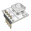
Can I ask you guys, what does it say on the back of your sensors? I ask because the MPU9150, 4 in 1 sensor I ordered says this on the back...
I'm curious to know why it doesn't say "Temprature" on the back as well, as it is meant to be a 4 in 1 sensor (unless I as sent the wrong one), and might go to answer why the temperature is not updating.
That is correct the MPU9150 does not do temperature if you look on the spec sheet from Sparkfun.
Interesting. That's not what the store description says...
confused
Yep, ez robot states it's a 4 in 1.... I guess we only get a 3 in 1?
The MPU9150 does provide temperature but I have not seen this well documented on any datasheets or from any vendors. I have an MPU9150 I got from ebay (Non-EZ-Robot) and it will provide temperature data, but I don't believe it was meant to provide room temp or weather type temp. I think of it as more like an "operating" system temp, like CPU temp sensor in a PC. In my experiments I used a heat gun to blow on the device the temperature would climb. Once the heat source was removed it slowly dropped back down.
here is the spec info on MPU9150 Features: