PRO
afcorson
Australia
Asked
Do you know if ARC is compatible with a RoboClaw 2x30A Motor Controller? - see link: https://www.basicmicro.com/RoboClaw-2x30A-Motor-Controller_p_9.html
Related Hardware (view all EZB hardware)
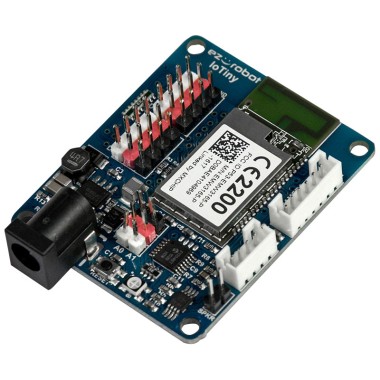
EZ-B Iotiny
by EZ-Robot
Control IoTiny with Synthiam ARC: 100MHz Cortex‑M4 Wi‑Fi IoT/robot controller-camera, servos, ADC, I2C and digital I/O for easy internet automation
Wi-Fi / USB
Servos
8
Camera
Audio
UART
✕
I2C
ADC
✕
Digital
✕

Most defiantly ARC and the EZB are compatible with Roboclaw. Although I haven't used the Roboclaw I was looking into it for my robot.I ended up going with Sabertooth motor controller with a X2 Kangaroo attached for position and speed control. You can control the Roboclaw 4 different ways and is able to receive feedback from limit switches, pots or encoders. Depending on what you want to do with it will depend how you set it up and the feedback device you use. It will defiantly have a learning curve and you'll have to study and find out how to send commands to it to control it. I'd suggest you download and start reading it's manual. That will have all the info you'll need to decide how to set it up and operate it. Good luck and have fun!
I have tried everything I can think of to get my Roboclaw 2.x30 V5E to work but to no avail. I can't get past the onboard error LED flashing 3 or 4 times indicating the Logic Battery is either too high or too low. I have tried 3.3v, 7.2v and 5v connected to the LB-in. I wanted to disable the logic battery but there seems to be no way of doing this with this model. I have used the Sabertooth Control, set the baud rate and simple serial type correctly, so I don't know what the problem is. Any advice appreciated. roboclaw_datasheet_2x30A.pdf roboclaw_user_manual.pdf
Have you contacted the manufacturer? Sounds like maybe it’s a damaged unit? Or they need to update their manual to provide the features.
There is no Roboclaw control in ARC, besides understating how RoboClaw works is also important to familiarize with ARC Custom Movement Control and EZ or JS scripting.
Some points:
Oh - ptp, i assumed based on his question that the roboclaw hbridge used the same protocol as the sabertooth. My bad
Yes to all 4 questions. See images for wiring. I doubt the EZB will work until the error is cleared on the Roboclaw. I have the 24v power supply connected to the Roboclaw main +-. The motor's brakes are connected directly to the 24v battery. The left and right motors are connected to M1A, M1B, M2A and M2B on the Roboclaw. The EZB has D5 connected to S1 on the Roboclaw. I have also attached an image of the general settings of the vendor's software. According to the user manual, error light flashing 3 times indicates the logic battery is too high, flashing 4 times and it is too low. To my mind this is nonsense as I am not using a logic battery and the unit is supposed to automatically set the logic power source. I have tried connecting 3.3v power from the EZB to the LB-in on the Roboclaw and also 5v power to same. No luck there either. I may have to contact the vendor unless you have some ideas I can try.
How are you powering the EZB ? Source and voltage.
I'll post a solution to your problem.