
Robotz012248
USA
Asked
— Edited
L298n Motor Driver
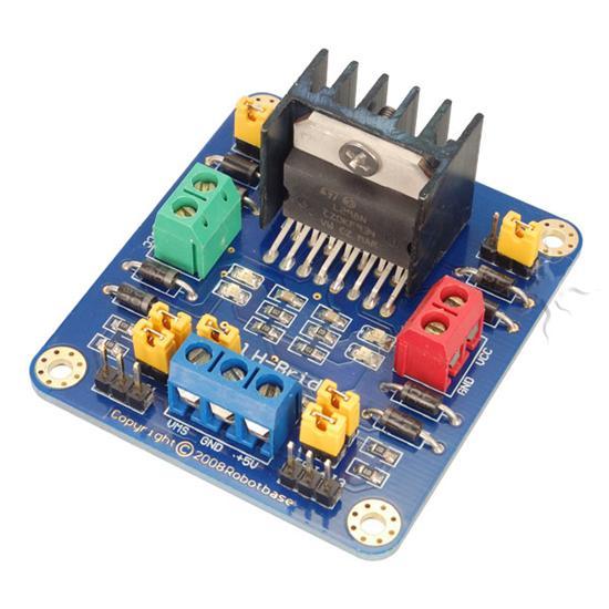
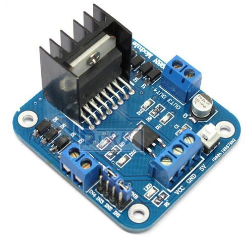
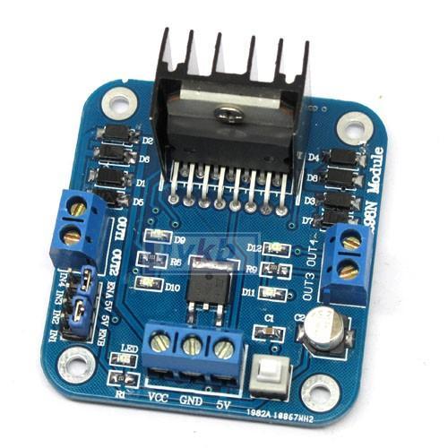
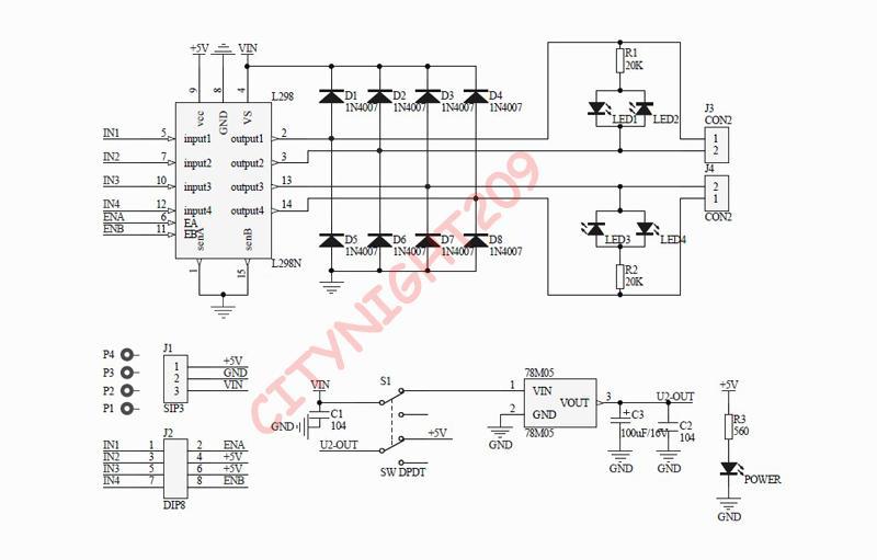
I ordered this before my stroke and now I can't remember how to wire it up? I attac hed pics and diagram. Any help would be greetly appreciated. Lloyd

DJ, "PWM of the EZ-B" is it simply any digital port???
@ Bookmaker ,
I would never speak for DJ..but I am very sure the answer is....'YES'. All the digital port signal pins can provide PWM.
Question I have is how you control PWM control in an EZ script...do I use servo(DX,XX)?
Also, will VB script work in next ARC version?
v/r
Kevin
@Robotz012248 - I just hooked up my motor controller (just like your but the layout is a little different) and it works brilliantly. I did find a couple of tricks that may help you. I soldered a female plug to the end of two servo cables. One end I plugged onto the motor controller and the other end plugged onto the EZ-B. The way I plugged it onto the board I only used two servo cables and two extra female ends. See Pics.
@bret.tallent: I see what you did, however...........I'm a bit confused on the PWM that DJ added. I need more info on it. DJ told me to prob for the pins that DO NOT have +5 volts on them. On my controller I have 4 pins that are marked: ENA - 5v - 5v - ENB. these pins have a jumper on them from the factory. I'm thinking these are the "ENABLE PINS" Does that sound right? So the PWM would be connected to the enable pins???????? The other question. It looks like you attached only the (red) 5 volt pin on the three terminal screws that are motor voltage ( ie. VCC - Gnd - 5v ) Wouldn't the battery power leads (12 volts in my case) got to VCC, which would be positive, and battery ground to the GND terminal?
Yeah, I am unsure of the PWM pin he was referring to. I did not use that as I am only driving a small omnibot with this and his speed is acceptable as is. The PWM is only for changing the speed in this instance and I don't need that. And yes, good eye. I hadn't connected the power or motor wires yet as I did not want to convolute the image too much. I just wanted to show how I wired it to the EZ-B.
So that single red wire from the EZ-B powers the circuitry in the board, and thr connections from the battery power the motors. This is a pretty good set up but it takes 5 ports to run your motors. Not bad if you don't have too much other stuff, or are using more than one EZ-B.
Thanks for clearing it up for me.. Actually, I would have missed the 5 volts from the EZ B to the driver. You saved me on that one! Thank you bret. I guess I'll have to try to get DJ's attention on this and the PWM.
Actually DJ sent me a wirng diagram that showeed the 5v pin.
I received my motor controller from Dj and hooked it all up. The robot turns great but i cannot seem to get it to run forwards or backwards. When I select forward or backward, I can hear the motors engage on the gear for a split second then it will stop providing power to the motor. I am wondering if any one has run into a similar situation.
When setting up the controller I had to configure the ports so that it would turn in the correct directions. Before I had configured the ports to turn the correct direction, the robot was able to move in all 4 directions. but the directions were incorrect. ie left was forward, forward was turning right, backwards was right, and right was backwards. I wouldn't have a problem with it but it effects the radar control while the robot is moving.
I can also configure the ports so the the robot will go forwards and backwards correctly but not be able to turn.
I have double checked all my connections and am not seeing any loose wires, or wires plugged into an incorrect port on the board.
thank you for the help!
Aaron