Robotz012248
USA
Asked
— Edited
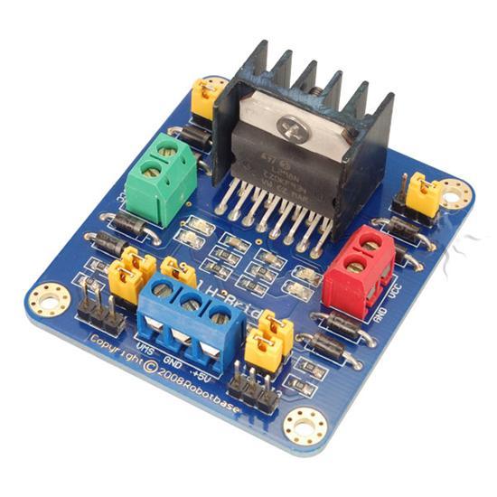
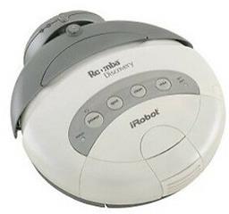
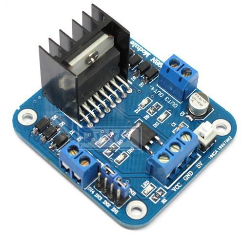
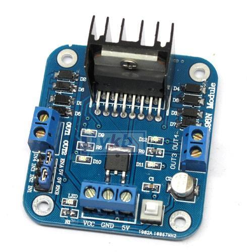
L298n Motor Driver
I ordered this before my stroke and now I can't remember how to wire it up? I attac hed pics and diagram. Any help would be greetly appreciated. Lloyd

Hey Lloyd!
Good to see you remembered how to upload photos! You're almost back to your old self! Just like riding a bike!
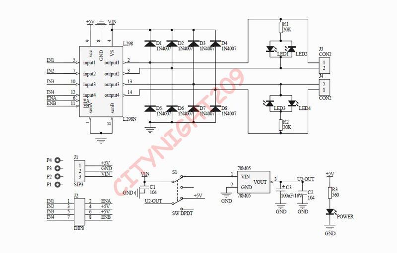
I drew a diagram for you. And in summary, this is how it works...
In ARC, use the HBridge Motor Control. Press the Config button and select the pins that you connected the L298's INPUT Pins too (example D1, D2, D3, D4).
If the directions are reversed, simply go back into the CONFIG menu of the HBridge Control and change the configuration around to D4, D3, D2, D1. You may need to try a few combinations to get it right. Sometimes it confuses me too!
PS, the only reason i didn't begin the connections of the L298 INPUTS to the EZ-B at port D0 in the diagram was because there wasn't much room when drawing it haha
haha
Thank you for your help DJ. I'm a long ways from being back to myold self. I know its going to be a long road back. I know , I recovered from my first one so I know it can be done. I'm determined to overcome. You once said you would lik my story so in the near time I will write it all down for you. I have a friend that has offered to give some of his time to hep me with my robot progects. Thanks again for answerrig my call for help. Lloyd
I'd very much like your story - you are a great inspiration to many people, driven by your determination to never give up. Your passion for Robotics is admirable and I think your story should be shared. How many other people are building their own robot arm or robot wheelchair or robot assisting device? Just you man!
Much thanks to you DJ. I've always been a very determined individual. You will seee in my story some of the things I have had to over com in my life. It would please me so very much if I could enspire anyone, in any way. One of my tennents in life has been .............. as I age I never want to find myself saying "I wish I would have............" If I find I have difficulty doing something, I just find a new or different way to do it! If that meens I have to build a device to enable me then thats what I attempt to do. Enough of that for now. I have another questiion about the L298N driver. The driver still doesnt allow for controlling motor speed. Could I put linear taper pots in between the motor outputs and the motor itslef? Motor power will be from 12 volt, 9 aMh battery. What value would I use for this? 5K, 10K, or what? Would this work at all? Thanks again,
To control the motor speed, you can use the new PWM control in ARC (if you have the latest version).
Connect the one pin from the PWM of the EZ-B to the ENABLE pins of the HBridge. To figure out what pins to connect on the HBridge, first pull the jumpers off. Then probe with a volt meter to see what pin does NOT have voltage. Do not connect the EZ-B to the pins with +5. Instead, connect the EZ-B PWM to the two pins that do not have +5.
The one PWM will control both enable pins of the HBridge
@DJ - is this the same motor controller you are now offering? And it takes 4 DO ports to operate? Does the one you sell also take 4 ports function?
Thank you for your help DJ. Much appreciated. @ bret.tallent: This is not the motor controller that DJ is selling, that only takes one connection to the EZ B.
@Dj thanks! mm!... How many volts and amps should be the energy source? Would it work with a 9 volt 2 amp?