United Kingdom
Asked — Edited

Inmoov Heavy Head And How Do Other Inmoovers Cable Their Robots?

Hi everyone Very interested in how you all approach the InMoov arm wiring and hiding the cables between arms and torso. Very interesting how you wired it Merne.

Also I have the speaker in the mouth and find that head settles forward on power down and tends to pull the neck out of the neck socket [bob houston style neck]. have a great weekend lorn


ARC Pro

Upgrade to ARC Pro

ARC Pro is more than a tool; it's a creative playground for robot enthusiasts, where you can turn your wildest ideas into reality.

#1  

Damm it. I just wrote up 3 paragraphs only to hit the wrong button on my phone while uploading pictures and lost all of my typing I put in, flower iPhones? stress

@Lorn, Second try, lol :D

I used 14 pin flat cable and servo cables both work fine. I ran all my cables out of the forarm then up thought the biceps out the back top of the biceps where the back bicep covers attach. Then were the servo for the rotcenter(arm rotates) attaches to that part there is a square hole is were I run all my cables thought.

Then I run all the wires, though the slots on the back side of the pivconnector(s) the runs/lays between the top torso part except the rotcenter wire that the servo attaches to outside that will run though the square hole on the servo pivmit( the part that rotates the arm up and down. This wire then goes on the back side of the torso to my EZB controller.

The pot that controls the shoulder Pot runs outside up into the other wires then though a slot on the torso to my EZB controller too. Make sure to leave a little slack and all the cables for movement of the parts.

For the shoulder servo wires I run them up in between the shoulder holder back on on top of the torso with the other wires going though the slot on the toros to the controller too.

User-inserted image

User-inserted image

User-inserted image

User-inserted image

User-inserted image

User-inserted image

User-inserted image

User-inserted image

As for the neck moving down when the servo power is released, we need to as bhouston and anyone else who uses Bob's design. I use Mr. Drupp's neck design, I find it look more like a neck. I think Bob has done a great job of several modifications to the Inmoov for our community but I like Drupp's neck, personal preference :D

You might have the neck position part to loose or not a strong enough serval to hold his position when there's no power to it hope all this helps.

Cheers

Edited Ohgreat, now Bob's gonna be mad at me for not following his tutorial on uploading pictures sorry Bob. stress;) :)

#2  

@Lorn.

Forgot to mention, all Inmoov builders wires their's a little different so you might want to see if others share their wiring experiences.

United Kingdom
#3  

Hi Merne Great pictures and very nice InMoov. And thanks for taking the time to write it [twice!] I am going to rewire same routes as you have done, to keep it all tidy.

I think the problem I am having with the neck [which has only just started to happen since I finally got around to fitting his skull top/side plates and ears in place] is both weight and the round cup over the ball joint wearing out a bit. So its not properly gripping the ball joint. Tried tightening up the servo linkages, and even thought about adding weights at the back of the head to hold it in place.

I am planning to print the Drupp neck when my new printer arrives. Everyone keeps saying I should try it. My Wanhoa i3 control board failed again so I have ordered a new original Prussa Mk-2S printer so just waiting on that to arrive.

I had almost finished printing a new arm to fit the flexi-hand modification to, so thats yet to be completed totally. Also am planning on printing another head, so lots to keep me busy.

Also must get a voice BOT working! Oh and a new stand for him... Have a great Sunday Lorn

#4  

Thanks Lorn. You could try a spring in the back of the head to help keep it in place for now until you get Drupp's neck complete.

#5  

Hi Lorn, I have seen somewhere somebody had a spring that fit around the piston that raises the head. It was about 2 cm dia and 5 cm or so long.

#6  

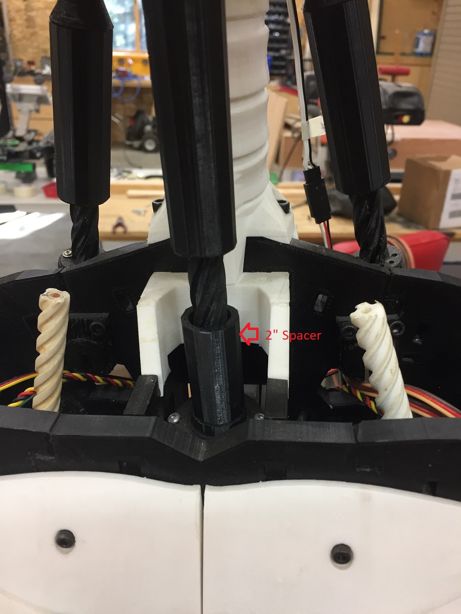
@lornecampbell, I've put a 2"spacer on the piston that lifts the head so that it can only go down so far. This will prevent the neck joint from pulling off. The spacer is made from 2" of the ThroatPistonBase. Cut off the end that doesn't have any threads in it. Also make sure that ball joint fits tight. I put some grease it as well. Hope this helps. User-inserted image

Canada
#7  

Hi Lorn, Look at post # 100 under my Inmoov project,

https://synthiam.com/Community/Questions/7706&page=10

It show the spring i use to hold the head straight when the servo is release. :D

United Kingdom
#8  

Hi everyone thanks for all your comments and pictures. I will mod the neck and that looks like it will sort out the problem. Plus my new printer should arrive this week so I can get 3D printing again. Lorn

#9  

Hi there, I know it's been awhile... I also went through all the iterations of neck on the InMoov starting with the original Flex/Extend/Rotate then moved to Bob Houston's neck, then made mods, then built Drupp's Parloma neck. I've designed a two servo lead screw driven neck that provides precise control over head position and fits into the parloma neck footprint: https://www.thingiverse.com/thing:3781132

Enjoy!

United Kingdom
#10  

This is very interesting, I have built the Drupp Parloma neck design on my InMoov a few years back.

What advantages does this new design have over the parloma neck design?

#11  

Control over the head is more precise and certain. There is too much play in the parloma neck, and mine developed slippage in one of the gears. Tracking is more easily facilitated. Active range of motion is increased. See initial video: https://youtu.be/R95s6OxsMGg

United Kingdom
#12  

Thanks, I might have a closer look at your design and give it ago. Although I hadn’t experienced play and slippage, there is a lack of range of motion as you have highlighted on the parloma neck design, which has bugged me for a while!

I like your YouTube clip.

#13  

I use Gael's neck design it is like Bob Houston's design but I like it better, I use  ez-robot HD servos and I have no issues with movement or  head dropping.  I  print the neck gears with nylon and the other parts with PET G.  I use an IO-tiny in each wrist to control fingers elbow and shoulder servo's so no wires leave the arms. no long wire runs just a pos and neg power wire. to the torso.  cool

#14  

@nallycat - What a great idea! Got any photos of mounting and routing cables to the ioTinys? ARC supports five boards - I have 3 right now.

None of the past necks really performed to my expectations, hence the new design. Plus, I love a project. The linear drive mechanism provides excellent fine tuned control over head position.

Thanks!

#15  

User-inserted image @mayaway   I took these pictures to show you the Io-Tiny locations   one in each Wrist.  you can see no wires going to the torso.  except the power, also you can see the elbow is Aerius design and it uses only a EZ_ROBOT HD servo to raise the arm, I advise if anyone is going to make this, make all the gears out of nylon filament as I had PLA break, ABS and Pet -g flexed to much and the gears slipped under load .    User-inserted image

United Kingdom
#16  

Hi all Great idea with the IoTiny in the arms.

#17   — Edited

@nallycat Thank you! Any pointers for: Printing in nylon. I have some filament but never had luck with it. I have an 8" Maker Farm Pegasus. Any tips for what works for you? Hmm, Aerius Design? What, where is that? If the servo is "outside" the arm, I might consider building a linear lead screw drive for that! Anything to look out for routing the 2 shoulder, 1 elbow cables down to the ioTiny? Esp up where the movement is? Oh yeah, any hurdles getting motions in sync with all the boards? Do you just call the MovementPanels from script? 1.D0, 2.D0

#18  

@Iomcampbell  Thanks you,  if you look at the pictures I posted you will see only one tendon on each servo for the fingers, it is a design of mine that I tested for about a year.  works great and very easy to adjust, I will post a video when I can find the time. @mayaway  The elbow is a planitary gear and works very well if it is printed correctly.   here is the site to build one https://www.thingiverse.com/thing:2778760  do this as a test as it took a few tries to get it working correct.  to print nylon you must make sure it is very dry, nylon filament is very hydroscopic and picks up water like a sponge.  I use a food dehydrator to keep it dry. without one you will need to dry in your oven for 6 hours or longer around 150 deg. it will not print with any water present  extruder 250 to 270 bed 80 print the gears no infill.  I print on glass with hairspray.  As far as using two Io-Tiny all the inmoov owners that I know use at least two ez-robot controllers as there are so many servos.  the difference is I use one ez-robot controller and 2 Io-tiny's not a big deal.  the other advantage of this elbow is the forarm cover does not have to be on and that makes working on the fingers very easy.  also the hand can touch the head try that with Gaels elbow you can,t do it.   also the forarm stays put even with power off.    the elbow is very well designed but is a pain in the behind to get it correct and you must use ez-robot hd servos no other servos will work.

#19  

@nallycat - Are those nylon temps in *C or *F

Canada
#20  

User-inserted image

I have used the ioTiny in each arm from the beginning, much easier wiring.   Nallycat  is correct about drying nylon although I use elmers white glue for the bed. Nylon print temps

#21   — Edited

@mayaway   I Knew you were from the U.S.A. but the amounts are in celcius .  we older Canadians were Imperial but be converted to Metric so now we are ampidextrous.  did you have a chance to look at the videos on the site https://www.thingiverse.com/thing:2778760. It shows the range of motion.  https://www.youtube.com/watch?v=nzcvqF31b7g&t=41s

#22  

@3dGuy  Do you dilute the Elmers glue with water and how much, I have been using aussie hair spray as that was one of the recommend hairspray's and it does work very well I never have lifting or warping, but it has perfume and when I print it smells like a Hair salon.  I cannot remember if I got the IoTiny  idea from your design. but thanks if I did, I love your designs.  just one last thing if you look at the Aerius elbow you can see he places the ioTiny on a support on the elbow made for it.  I had mine in the wrist before I made the new elbows but I would think the location is easier to work on the ioTiny in the aerius  elbow. I am to lazy to change locations though.

#23  

@nallycat - Thank you! Yes. The whole construction is quite impressive. Will the arm fully extend? I can see that it goes to 130* flexion which is a great improvement. How do you manage only one braided line to each finger? Do you have return springs tucked away somewhere?

Canada
#24  

@nallycat,   I  don't dilute it. Just spead it evenly with a paint brush. Let it dry for a couple minutes once the bed come to temperature.

#25  

Thanks 3dGuy;  I will definately give the elmers glue idea a try, is it easy to clean up afterwards. the hairspray is easy,  just clean with hot water. @mayaway  Yes the arm fully extends.  I will have to make a video about the hands.  hard to describe you will have to see. you don't have to reprint the original hands.

#26  

Thanks 3dGuy; I've been using CubeStick for $9 USD a bottle but it lasts a long time. I print mostly ABS on a 60*C Bed - I've wondered about good alternatives.  @nallycat oh do! on vid of the hands - their action could certainly be improved upon. The original setup is just fussy. I've thought about a lead screw linear drive solution for there too. It sounds like you do have a powered flexion against a spring loaded extension in the fingers?