rgordon
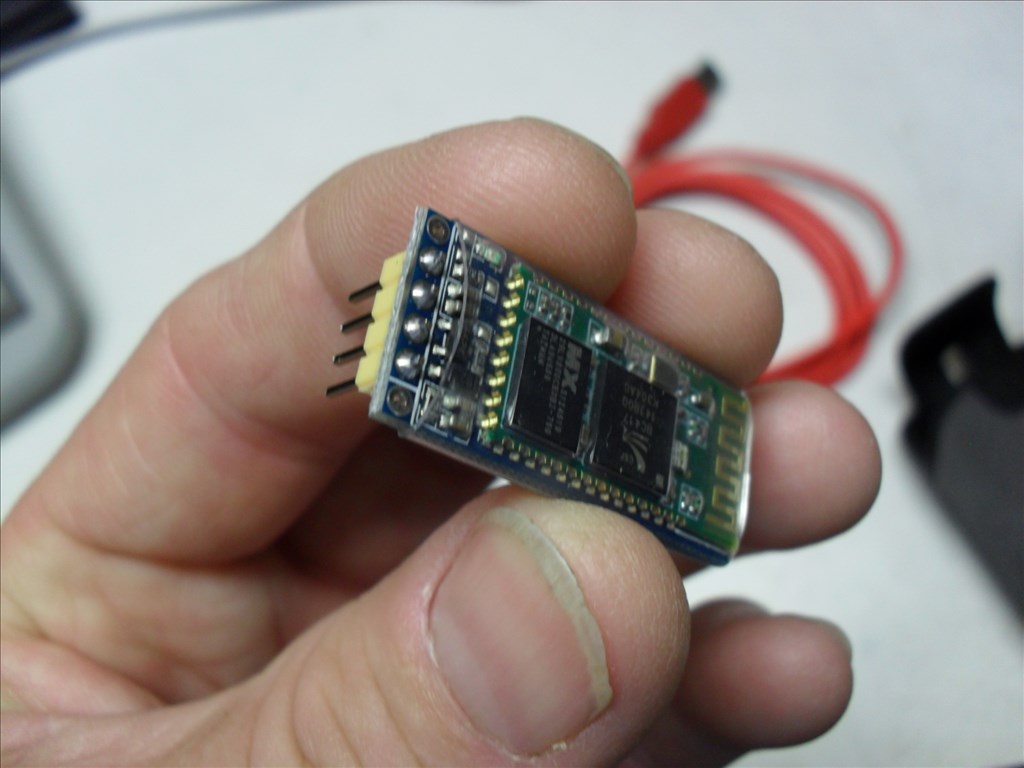
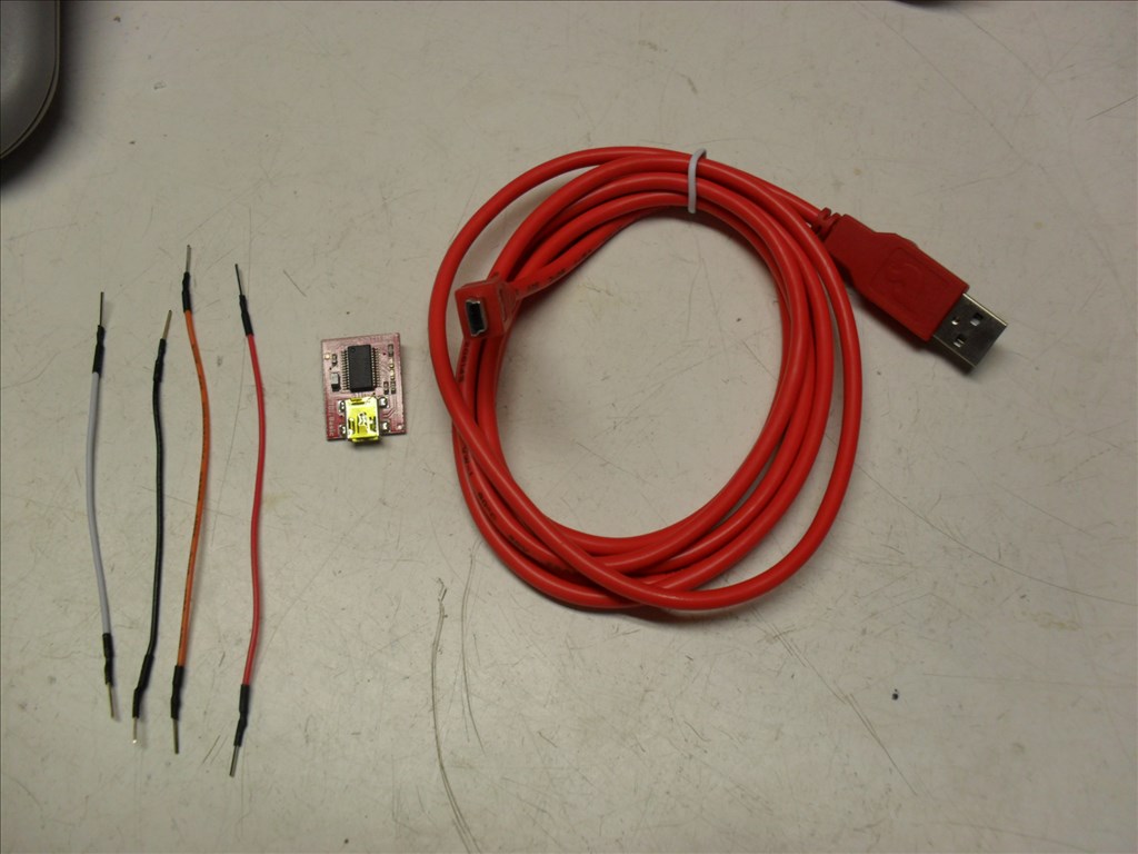
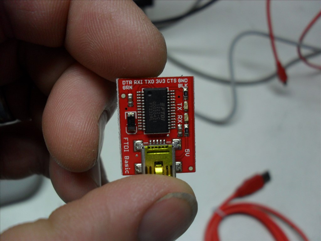
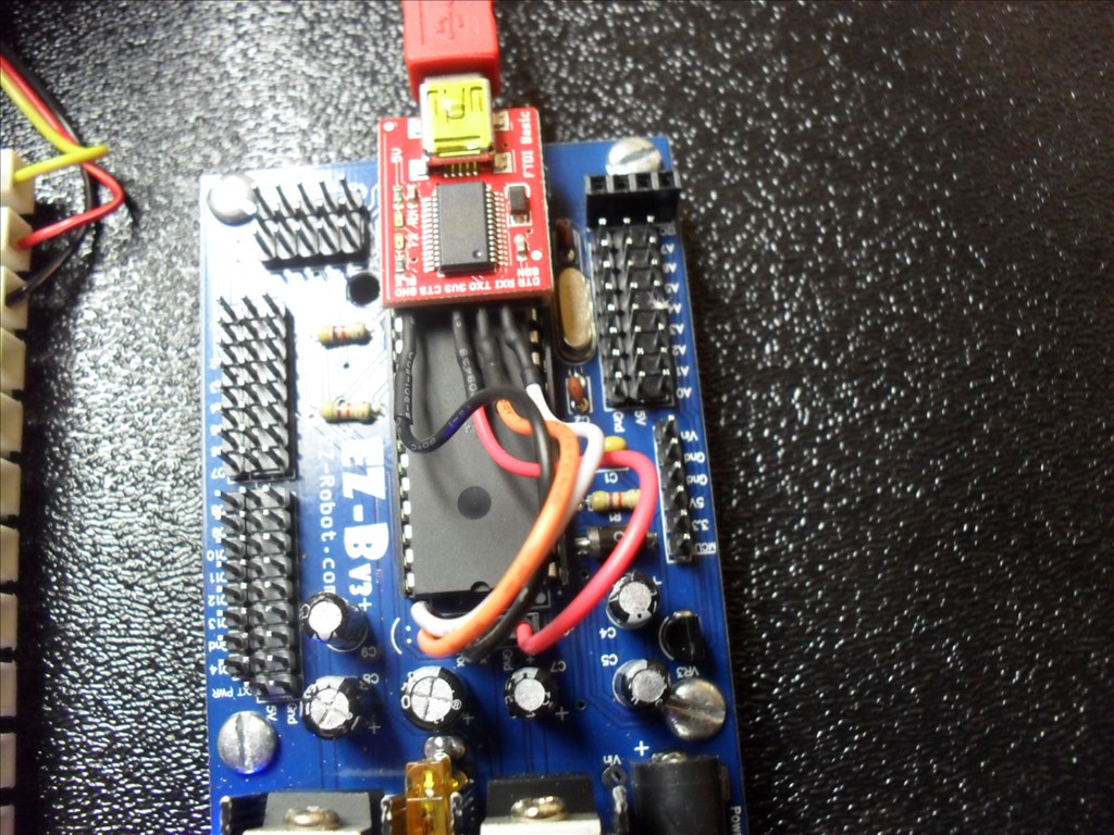
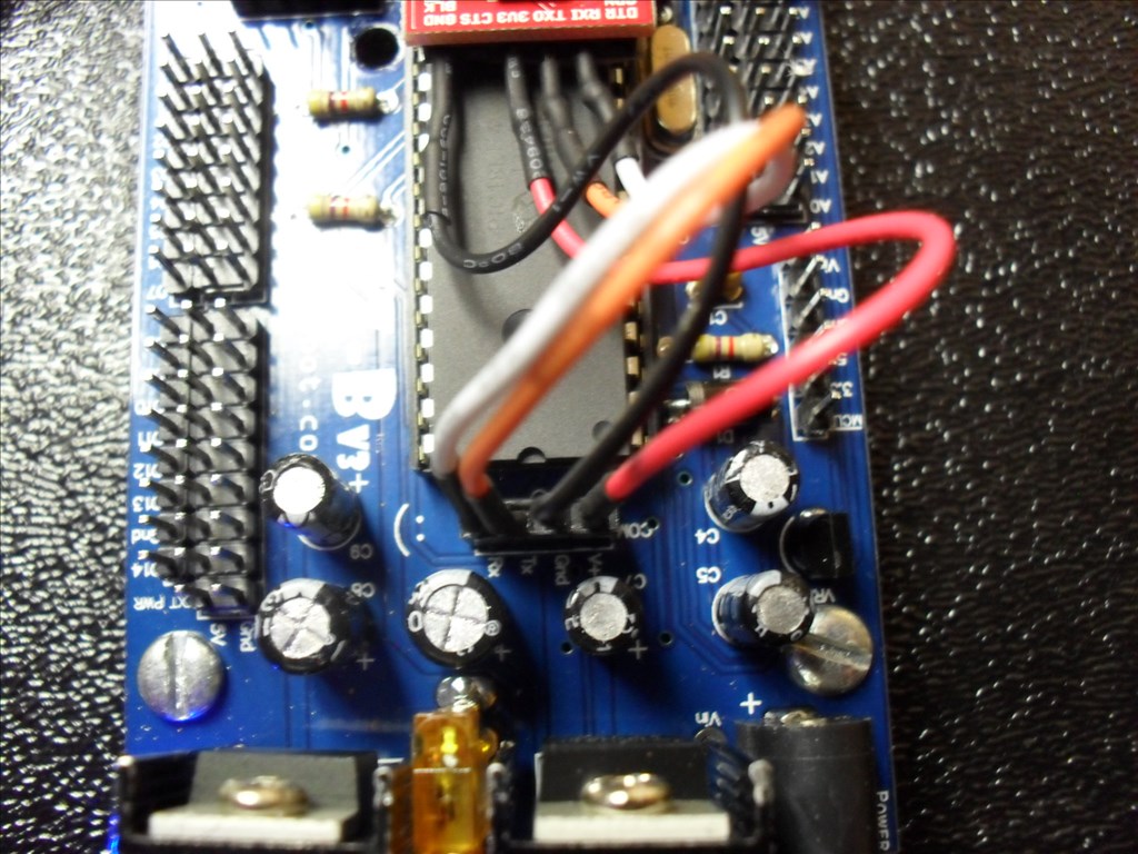
Here is how I hooked up the SparkFun FTDI (USB to TTL) Adapter in place of the Bluetooth module that sits on top of the EZ-B.
- I very carefully removed the Bluetooth module from the EZ-B by using a small flat blade screw driver to pry it up. The double sided tape eventually let loose from the IC Chip and I pulled the module free from the EZ-B header .
I used the male jumpers that I got from the EZ Robot Store to hook up the FTDI header to the EZ-B header. VCC to VCC <- EDIT: Found out this connection is not needed. GND to GND Tx to Tx Rx to Rx (Yes that's right Tx to Tx and Rx to Rx. I thought it should be Tx to Rx and Rx to Tx but that did not work.)
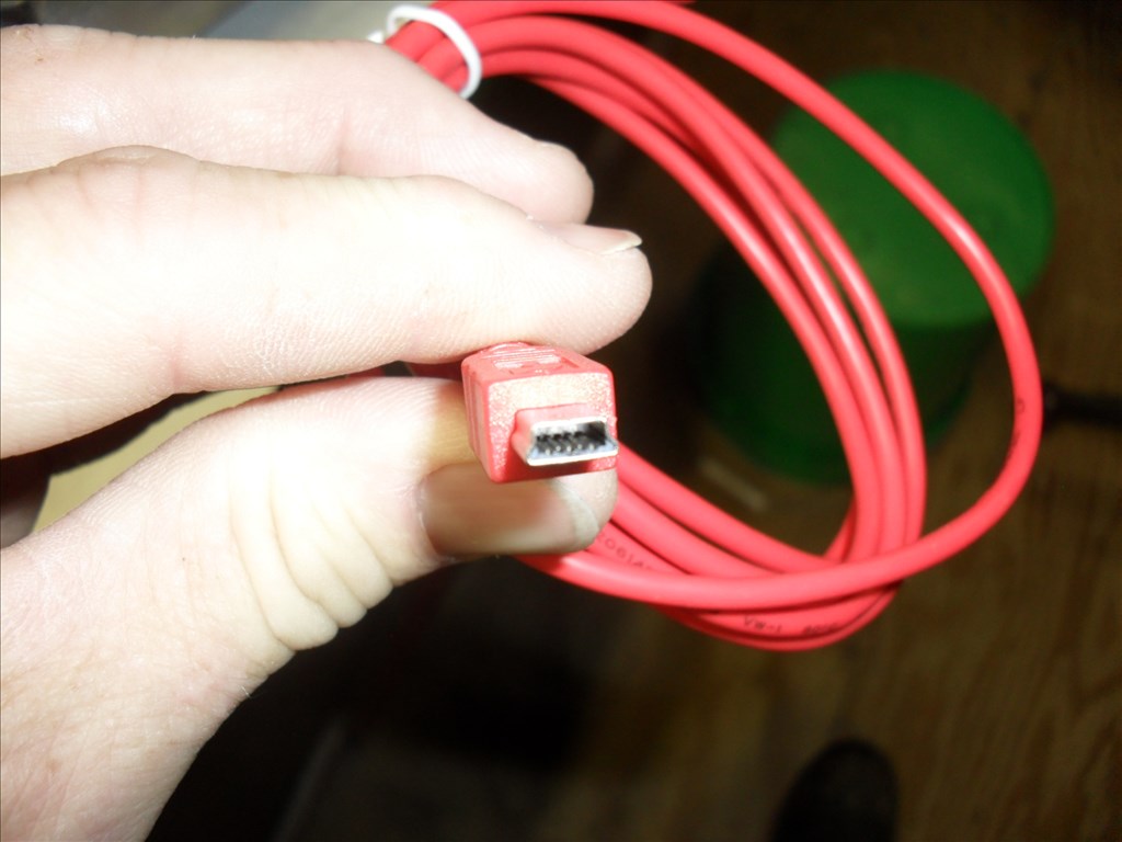
I hooked the SparkFun Mini-B cable from the FTDI board to the ASUS Mini ITX motherboard.
I powered up the EZ-B using a battery pack and then powered up the ASUS Mini ITX motherboard.
Windows 7 Home Edition (64 Bit) informed me that it could not find a driver so I let it search the internet.
It eventually found, loaded and installed a "FT232 USB UART" diver and assigned it to COM 7.
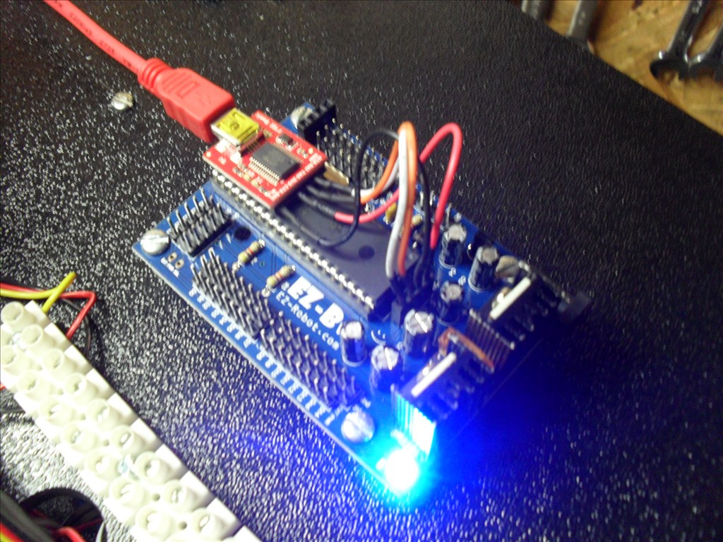
I started ARC, chose COM 7 and clicked on Connect. The EZ-B blue LED went from blinking to solid blue and all looked good. I hooked a servo to D0 and tested its operation with good results.
Notice anything interesting in the picture above?..... When I unhooked the battery pack from the EZ-B the EZ-B remained on. It was being powered from the Mini ITX. Connection was not lost. The blue LED remained on. However, I found that the servo would not work anymore until I hooked the EZ-B battery pack back up.
<- EDIT: Found out the VCC to VCC connection is not needed. I have now removed the VCC connection between the EZ-B and the FTDI.

that last part is interesting. Thanks for the info! ill bookmark this for sources later.
@rgordon Yep, you'll find that the USB from the mini-itx will power the EZ-B but it will be limited by the internal 3.3V regulator of the FTDI chip (50mA). I would suggest just leaving the VCC connection out and powering the board strictly from the barrel jack (or externally). This VCC to VCC connection is essentially taking regulated 5V from the EZ-B and feeding it into the 3.3V output from the FTDI, probably not advisable.
Without the VCC line from the FTDI connected you will still be able to communicate no prob, as long as the GND to GND connection is being made the RX/TX logic will reference the same GND reference when grounds are shared.
Thanks for the tutorial! This is a question that comes up in the forums/support quite often.
well done
@skater_j10 beat me to it (for a change ).
).
Nice tutorial, this will come in handy. And good job on the links
Very useful info @rgordon
Thanks
The un-named USB TTL adapter that came with my Elechouse WiFi adapter also needs to be connected TX to TX and RX to RX, so this appears to be a common mis-labeling on these adapters (ie, they are telling the user what pin to hook up to, rather than the function of the pin).
Alan
Hey guys...should I go back and replace the pictures so they don't show the VCC connection or just leave it and let the EDIT notes take care of it?
I'd say it's clear enough without changing the pictures so it's up to you really.