
Mulberry
USA
Asked
— Edited
H Bridge Not Needed If Motor Not Reversed?
Hopefully this is straightforward. If I am NOT reversing a 12 volt motor but just turning it on then off then I don't need an H-Bridge, correct? Power will be provided by an outside source.
Thanks,
Daniel

You could possibly get away with using the Transistor/Mosfet based switching circuit to enable and disable the motor. Since it will only be required to turn one direction this would be enough however you would need to check the components of the circuit to ensure they can cope with the current. You will also need to include flyback diodes.
My Transistor Switching Circuit Tutorial
Hello Daniel , a hbridge is reversable but if you just need a simple on / off control then you caN use a darlington switching transistor. The pos connection is always connected to the power source. The Darlington transistor closes to connect the ground completing the circuit and turning your motor on.
EDIT-I see Rich also posted while I was putting the post together and includes a more detailed tutorial. Great job on that tutorial I don't think I saw it in that much detail before.
You need a 1k ohm resistor , Darlington transistor and one 60v or higher diode. The resistor goes inline from the digital pin of ez b and protects the digital output. The diode prevents feedback from a motor starting and stopping.. here is a generic sketch of how this is arranged when using a motor.
One other option would be a relay. If you have several things you want to turn off and on you could get a relay board that has multiple. relays and is compatible with EZ-B.
True, a relay board could do it but is pretty much only a transistor switching circuit and relay anyway... I guess if making circuits is not something you like to do then it's the better option.
This 5vdc relay will work great with the EZB. Digital ports can open and close each relay and the DC motor be turned on an off when the relay operates. This one can individually operate two devices.
www.ebay.com/itm/5V-Two-2-Channel-Relay-Module-With-optocoupler-For-PIC-AVR-DSP-ARM-Arduino-/181026509345?pt=LH_DefaultDomain_0&hash=item2a26055221
These relays are all over the place. You can get them on Amazon and Ebay. You can get them with from one to very many relays.
Excellent. Thanks everyone.
So David this is for the motor that turns my soil sampler. I'm using a servo to open the door, an actuator to run the arm out and a 12 volt motor to spin the scoop. Perhaps I'm doing the Rube Goldberg approach again by making this too complicated. I did consider wiring my scoop with my actuator into a single connection so it comes out spinning. Do you mind describing what you did?
Daniel
Sure Daniel,
Actually I really cheated here. I was lucky enough to score one of Mike Joyce's original Soil Sampler units. After I installed it in the tread section I attached it to both one of the chest buttons and a relay activated by a digital port on EZB. That way I can either activate the automation by a chest button or with ARC. I don't have a motor that opens the sampler door. When the unit starts up it just pushes the scoop out through the door and then it starts to spin. You can see it working at the end of this vid:
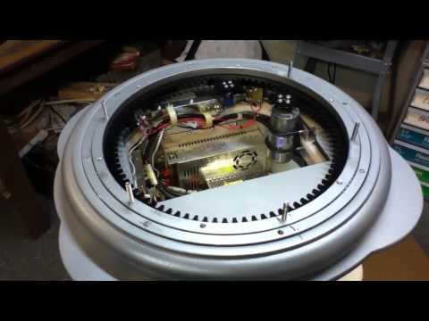
Here's a pic of the unit:
Here's mike Joyce's installation page with some good info and pics and vids of the unit: www.b9robotbuildersclub.com/pub/parts/b90002/soilsampler.html