
Asked
— Edited
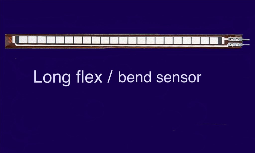
Flex Sensors
Has anybody used, or know if these can be used with the EZ-B v4? And if do, how do they connect? These flex/bend sensors would be great if they worked with the EZ-B and ARC. Not much information on power, but they can be used on analog or digital (although I think analog would be better).

A bit of an update in regards to the flex sensors. After a couple of weeks break after receiving some very bad news regarding family issues, I've got back to robots to take my mind of things. Anyway, I got home today and found that the sensors had arrived. But unfortunately the happy feeling soon went away after I hooked them up to my v4.
Using an ADC reader set at 100ms update time, I first tried wiring one up just using signal and ground pins on an analog port. With the sensor flat, the noise reading fluctuated quite a bit between 0 and 7, and bending the sensors didn't make any difference.
I then tried the way that was documented on the website using a 10k pull up resistor (as they recommended). I ran the Vcc through a 5v regulator to a digital pin, and tied in the 10k between the ground and signal wires and ran them to the ground and signal pins on an analog port. It reduced the noise (readings between 0 and 4, mostly between 0 and 2), but flexing the sensor made little to no difference whatsoever.
So unless anyone has any other ideas, I think I just blew $60 (3 sensors, shipping, import tax) on something I can't use. So I might look in to one of the ideas Richard or Dave mentioned. Kinda sucks though, not just for the waste of cash, but these would have been ideal with easy fitting to the bumpers. mad
Hmmm @Steve G you should definitely get some response on the ADC, instead of 5V I would tie the 10kohm pullup resistor to 3.3V. The ADC pins are 5V tolerant but can only read a voltage between 0-3.3V.
Reading the specs it looks like the resistance changes from 10kohm to 20kohm when flexed. So initially if you are using a 10kohm pullup you should see a value of 1.65V on the ADC port and when flexed the voltage should go up to ~2.5V.
Please check if your solder joints are good on the sensor itself or double check if the correct ADC port is selected.
@Jeremie.
Thanks for the reply. I can confirm that the solder points are clean and well attached using a solder/flux mix (which I use elsewhere with good results). And I defiantly had the correct port selected from the config menu. The only voltage it was reading was flutuating between 0 and 0.2v at the most when either flexed or straight. I even tried different ADC ports just to be sure. I can try using the 10k on 3.3, but the documentation was using an Arduino on 5v on their example so I would have expected it to work.
@Steve G, Can you try reading the output from the sensor with a Voltmeter?
Will do. I'll try it tomorrow morning and report back.
Try swapping the leads on the sensor.
@Steve G... Another idea I tried for my robot Questor was using pieces of a metal measuring tape. It seemed to work fairly well but I never got around to actually installing it before I took Questor apart. What was nice was that it makes contact no matter where it is pressed along its entire length. The spring steel and specific shape of the tape measure allows it to spring back to normal after the robot moves away from the object it came into contact with. See post # 17
A further update on these sensors.
Thanks for the advice Jeremie and Dave. I tried hooking up the sensor again using Jeremie's idea of not using the regulator, and running all the wires straight off a 3.3 analog port with the 10k. No change.
Then I tried Dave's idea of swapping the wires around which made a very slight difference as the noise values were reduced between 0 and 2, so bending the strip changed the value to around 4 to 5 briefly, but it was too unstable to use because of the noise fluctuation causing false positives.
Then tried a combination of both Jeremie and Dave's ideas, and the reading shot up to 255. So I added back the 5v regulator on a digital power pin and tried again... SUCCESS. With the sensor strip flat, the reading sat around 185/190. With about a 5 degree bend the value dropped to 170. 20 degree bend, 150... and so on. Definitely a hugh difference and very much usable now. So now to tidy up the wiring and install the strips inside of the foam bumpers.
Thanks for all the advice Alan, Richard, Dave and Jeremie. I'm very grateful for the help. And to rgordon as well for your input. Where were you when I needed you? You could have saved me a few beer tokens . Seriously though, I had a look at your thread using the measuring tape idea. That's a pretty cool idea and may try that some time on another project. Thanks for the link.
Cheers everyone.
Steve.