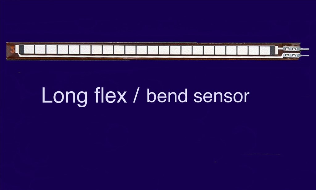
Welcome to Synthiam!

The easiest way to program the most powerful robots. Use technologies by leading industry experts. ARC is a free-to-use robot programming software that makes servo automation, computer vision, autonomous navigation, and artificial intelligence easy.

Get Started
United Kingdom
Asked — Edited

Flex Sensors

Has anybody used, or know if these can be used with the EZ-B v4? And if do, how do they connect? These flex/bend sensors would be great if they worked with the EZ-B and EZ-Builder. Not much information on power, but they can be used on analog or digital (although I think analog would be better).

Flex / bend sensors

User-inserted image


ARC Pro

Upgrade to ARC Pro

Unleash your creativity with the power of easy robot programming using Synthiam ARC Pro

AI Support Bot
Related Content
Synthiam
United Kingdom
#1  
The idea I had for these was to place them inside of a rubber or foam bumper of a tracked or wheeled robot, and act as a bumper sensor. When the bumper touches something like a door frame when the robot is turning, the flexing of the sensors would would trigger a script to stop motors, reverse, and re-track to avoid the obstical with a script.

These apparently work with Arduino, so they should work with an EZ-B.
PRO
Canada
#18  
Hmmm @Steve G you should definitely get some response on the ADC, instead of 5V I would tie the 10kohm pullup resistor to 3.3V. The ADC pins are 5V tolerant but can only read a voltage between 0-3.3V.

Reading the specs it looks like the resistance changes from 10kohm to 20kohm when flexed. So initially if you are using a 10kohm pullup you should see a value of 1.65V on the ADC port and when flexed the voltage should go up to ~2.5V.

Please check if your solder joints are good on the sensor itself or double check if the correct ADC port is selected.
United Kingdom
#19  
@Jeremie.

Thanks for the reply. I can confirm that the solder points are clean and well attached using a solder/flux mix (which I use elsewhere with good results). And I defiantly had the correct port selected from the config menu. The only voltage it was reading was flutuating between 0 and 0.2v at the most when either flexed or straight. I even tried different ADC ports just to be sure. I can try using the 10k on 3.3, but the documentation was using an Arduino on 5v on their example so I would have expected it to work.
PRO
Canada
#20  
@Steve G, Can you try reading the output from the sensor with a Voltmeter?
United Kingdom
#21  
Will do. I'll try it tomorrow morning and report back.
#23  
@Steve G...
Another idea I tried for my robot Questor was using pieces of a metal measuring tape. It seemed to work fairly well but I never got around to actually installing it before I took Questor apart. What was nice was that it makes contact no matter where it is pressed along its entire length. The spring steel and specific shape of the tape measure allows it to spring back to normal after the robot moves away from the object it came into contact with. See post # 17
United Kingdom
#24  
A further update on these sensors.

Thanks for the advice Jeremie and Dave. I tried hooking up the sensor again using Jeremie's idea of not using the regulator, and running all the wires straight off a 3.3 analog port with the 10k. No change.

Then I tried Dave's idea of swapping the wires around which made a very slight difference as the noise values were reduced between 0 and 2, so bending the strip changed the value to around 4 to 5 briefly, but it was too unstable to use because of the noise fluctuation causing false positives.

Then tried a combination of both Jeremie and Dave's ideas, and the reading shot up to 255. So I added back the 5v regulator on a digital power pin and tried again... SUCCESS. With the sensor strip flat, the reading sat around 185/190. With about a 5 degree bend the value dropped to 170. 20 degree bend, 150... and so on. Definitely a hugh difference and very much usable now. So now to tidy up the wiring and install the strips inside of the foam bumpers.

Thanks for all the advice Alan, Richard, Dave and Jeremie. I'm very grateful for the help. And to rgordon as well for your input. Where were you when I needed you? You could have saved me a few beer tokens :D. Seriously though, I had a look at your thread using the measuring tape idea. That's a pretty cool idea and may try that some time on another project. Thanks for the link.

Cheers everyone.

Steve.:)
#25  
Outstanding! Team work! So just make sure we feed it 5v useing the risistor your useing and make sure the leads are attached properly to the strip?

If you have time please do a how to and a video.
PRO
Canada
#26  
Great @Steve G, glad you got it working!

I don't mean to be a buzz kill but a flex sensor is essentially just a variable resistor, changing the leads around won't change anything in terms of resistance, remember there are only two leads and resistors aren't polarity sensitive. I can almost guarantee that the flex sensor can work on any voltage regardless if it's 3.3V, 5V, or otherwise.

My theory is that since the flex sensor has crimp connections onto the resistive substrate the plastic may have melted a little during soldering process and provided intermittent contact. After a few more tries it may have made contact again.

If the sensor starts reading really low again, it's likely the this is the case.
United Kingdom
#27  
@Dave.

No problem. I'll try to knock something up. Great teamwork. High 5's all round.;)

@Jeremie.

Truth be told, I didn't think the polarity would make a difference either. I was careful when soldering and can't see any visible damage/melted plastic as I had already tinned the wires so the soldering was very quick (there was a warning on the website saying to take care when soldering on to these sensors). I've got another one to do for the other bumper so I'll have another play around with that one and post back. BTW, you're not being a buzz kill dude. Any info you supply is always good and always appreciated.:)
United Kingdom
#28  
@Jeremie.

Maybe you were right (I didn't doubt it for a second). I wired up the second sensor, this time without a regulator, and it worked. I did the same with a third strip I had and it worked too:) . The readings now are 138/140 straight, then 120 and 10 degree bend, and so on. And the first one I hooked up now works without a regulator too. So it is possible I did do a little heat damage I can't see.

@Dave.

I took a couple of pics and posted a video demo of the second sensor I just wired up for you. It's pretty straight forward so you'll get this straight away. But if anyone else coming across this who wants to do the same, I wrote a quick tutorial as well. So here's how I did it...

1.) Using a servo extension cable, snip off the male connector and strip the white and red wires. Then tin the ends with solder.

User-inserted image


2.) In the middle of the White and black wires, strip back the outer casing to bare the wire, and tin with some solder.

User-inserted image


3.) Solder a 10 Kohm pull up resistor to the tinned White and black wires mentioned in step #2.

User-inserted image


4.) Carefully and quickly (as has been mentioned in above posts;) ), solder the White and red wires to the sensor connections.

User-inserted image


5.) Add some heat shrink to insulate the solder joins.

User-inserted image


6.) Connect the servo wire plug to an ADC port, wires matching the pins.

7.) load up an ADC meter in ARC, set the port the sensor is connected to, and bend away. As mentioned above, you should see a static reading of about 140, then the further the sensor is bent, the lower this value will drop (as seen in video below).:D

NOTE: For a little added stability, apply a small drop of clear silicone adhesive over the crimp connectors on the flex sensor, as thay are a bit fragile and this will give added strength.

PRO
Canada
#29  
Awesome @Steve G!

Thank you for sharing your findings and creating a great tutorial!
United Kingdom
#30  
No problem at all. Just happy I can share and give back to the community.:)
United Kingdom
#32  
No problem Dave.

Hope it helps.
#33  
Love the tutorial vid and that makes sense for specific animatronic things. However, and I apologize if I missed this in another thread, I was hoping to utilize the ADC ports to operate flex sensors in this sort of function:

http://www.instructables.com/id/Arduino-Wireless-Animatronic-Hand-1/

I tested it out with the Arduino and it does what I want it to do, I just dont know how to "map" in the script the adc flex sensor input to the real time output of servo control.

My hope is to use ADC 0-4 to control servos on D0-4 repsectively on the EZ-B4. The other issue I am having is using the MPU6050 variables to control servos as well.

I have some ability with circuits and assembly, but I have the programming skills equivalent to just learning that the strings on my shoes keep them on, next year I hope to learn to tie them...

Again I apologize if these question have been answered elsewhere.
PRO
Synthiam
#34  
That's easy - if you know how to do it in complicated C++ Arduino, then you can certainly do it even easier in ARC:D . Here's how...

1) Add a new EZ-Script control
- Project
- Add Control
- Scripting
- EZ-Script

2) Paste in this code

Code:


:loop

Servo(d0, getadc(adc0))
Servo(d1, getadc(adc1))
Servo(d2, getadc(adc2))
Servo(d3, getadc(adc3))
Servo(d4, getadc(adc4))

sleep(100)

goto(loop)


*Note: you may have to add a multiplier of sort to the GetADC() for each of the positions to dial in your accuracy. As you may have seen with your Arduino setup, the resister values on the flex sensor determine the accuracy and voltage being returned.
#35  
Thank you DJ! I am very proficient with copy and paste:) This makes me so happy, I've spent months reading how to books in arduino trying to figure out this I2c and wifi thing to no real avail. I can get the circuits to read right with meters but seldom get the code to operate correctly. (impatient with paying work getting in the way I guess), then I saw your creation and fell in love with it. A heartfelt thanks to you and your team.

What would the multiplier you speak of look like?
#36  
@artchas... analog values are from 1 to 255...servo positions are from 1 to 180, so you would use a "multiplier" to convert them to a servo position... The multiplier in this case is 0.7058... You would multiply all your analog readings by .7058 and that would covert them to a servo position from 1 to 180....

Code:


:loop
$adc0= Round(getadc(adc0) *.7058,0)
$adc1= Round(getadc(adc1) *.7058,0)
$adc2= Round(getadc(adc3) *.7058,0)
$adc3= Round(getadc(adc3) *.7058,0)
$adc4= Round(getadc(adc4) *.7058,0)

Servo(d0, $adc0)
Servo(d1, $adc1)
Servo(d2, $adc2)
Servo(d3, $adc3)
Servo(d4, $adc4)

sleep(100)

goto(loop)
#37  
Thank you Richard for the explanation!

So literally a mathematical function is in place. I see. Hypothetically I could then use this same concept to acquire and apply reading from a accelerometer for servo control as well?
I will look at the SC32 already in the EZB script and see how that is called for reading when I get time and see if I can figure that out. I am guessing I would need to use the add control function for the MPU6050, then set up a script that tells it to read that (similar to above with the exception that I would use the Hex address X or Y variables) and then assign that variable to a servo...? Am I in the ball park?

I see that the MMA7455 under I2C is already set to control servos in the settings. I will look at that too.

Thank you again