
Redzone
USA
Asked
— Edited
Finger Tip Sensors For Inmoov Hand
@Richard R. Are you going to use the finger tip sensora on your inmoov? I'm printing a new hand and would like to make use of the sensors but I don't think ezb support them directly.
Is it very hard to use the i2c from an andrino. Thanks.

If they were analog, then no problem. However, I still haven't done my homework on I2C yet LOL...I wish I could help you dude... Probably @Rich could help you on this one...
@Richard, it looks like the sensors are analog, but I am not sure how to wire it to the EZB. It only has to wires. I think it would connect to the ADC? So one wire would connect to the signal and the other to ground? I am not sure. Any help is most appreciated.
Thank you https://www.todayifoundout.com/index.php/2010/01/how-to-make-a-ridiculously-cheap-analog-pressure-sensor/
Ok, so if they are an analog sensors you can connect them to one of the 8 analog ports on your ezb.... One wire goes to ground and the other to the signal pin. To test it bring up the ADC value control in ARC... As you use the sensor (press on it) you should see the values change... What you would then do is create a script to read the adc port and when the pressure sensor on that port reaches a specific value (that you determine a head of time)... you can then have the servo stop or back off or whatever...
That sensor looks easy to build, might be the answer,but like you @merne, I have no idea how to hook it up to the EZB. The Robotshop and Solarbotics sell several different pressure/force sensors maybe one of those could be used.
....@Merne, you might need a resistor (10k maybe?) inline to make the sensor work a little better...
Also a good idea is to test it with a multimeter first before testing it on your ezb...
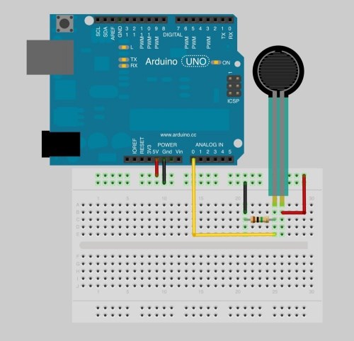
Thank you @Richard. I found a picture of an Arduino using a pressure sensor and it also has a resistor, a 1 MegaOhm Resistor. It also shows it is using 5v power. So is this how I would connect it or does the EBZ / sensor not need the power?
From that picture it looks like the resistor is on both Ground and signal. I not sure as I never used one of those pin boards before.
Also I thought the ADC on EZB is 3 volts, I could be wrong. Would that matter?
Here is the link. https://www.sparkfun.com/tutorials/389
Thank you.
@Merne... that's exactly how you would connect to the ezb... You are also correct, the analog ports on the ezb are 3.3V... You may need a lower value resistor... A direct connection from signal pin to ground won't hurt anything so you can experiment with resistor values until you get the numbers that work for you...
Thanks Richard. I will try that out. Just to be clear I would connect the ground and signal together or if using a resistor connect them both to the resistor then to ezb adc.
I am making thu resolved by you. Thanks.