Asked — Edited

Ez-B On/Off Switch

i thought about my wall-e... and thought...and thought... and one of the things i thought of was an on/off switch(painful to open up, close, open, close, etc.) I decided to put a power button/switch on the power cable, the only thing is which one! Not sure what websit to go to or what voltage to buy it from. Fine on connecting it. just need to know voltage and where.


ARC Pro

Upgrade to ARC Pro

Don't limit your robot's potential – subscribe to ARC Pro and transform it into a dynamic, intelligent machine.

United Kingdom
#1  

What size supply are you using? The 6xAA batteries or something bigger?

I'd assume any rocker or push switch will do the job to be honest though.
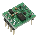
#3  

can you give a different link to the switch @McJeff? Dont really want to make an account. My dad (the money man of the house)doesnt really support my hobby so he wont want to either.(age 12)

#4  

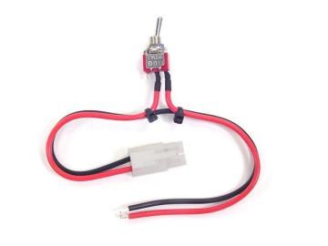
I have personnally used a simple rocker switch, buyed in a simple DIY store, for my Wall-E, like this one:

User-inserted image

and here is the result:

User-inserted image

It is working well...

Canada
#6  

that looks like it should work just fine

#7  

thanks.

@fredebec- Do you have a link to your wall-e(project showcase maybe?)? Looksd very clean.

#8  

@techno pro I like how that looks

#9  

Hello,

I'm looking forward to use the digital outputs of the EZ-B to turn on/off a night vision camera installed on my Rovio... I'm a total beginner, as you can guess. I thought I could use the data wire to connect it to the base of a transistor, but I could not find a proper way, somehow I always ended up with a lower voltage on the emitter of the transistor... and the cam needs quite exactly 5V. Anyone knows how to use the EZ board to turn on/off some devices powered through it? That would help me a lot since I want to be able to reinitialize my robot (rovio Wowwee) when I'm away (the cam has a different IP and a built-in on/off switch that allow me to reboot the rovio... however sometimes the camera just shuts down (while the robot is docking actually...) so the rovio shuts down too. Therefore I use the EZ board as a safety circuit, more reliable, that would allow to reboot any device or circuit installed on the robot.

Bottom line : how do I get to power on/off a port on the EZ board ? :)

Thanks a lot.

United Kingdom
#10  

To use the EZB to turn on and off external items such as lamps, cameras etc. follow the Tip120 & Tip122 Transistor Switching Circuit tutorial.

You needn't use the stripboard method however it does produce a nice and neat board. You can also put the components inline as mentioned further in that topic.

#11  

Ok, thanks a lot. I just saw your answer and I'm gonna look into the tip120 you mentioned. In the meantime I did something very... let say, "amateur" : I used a servo as a switch by attaching contacts to it!:D Not very satisfactory, though...

Another question : My EZ B disconnects and shuts down, for a reason that seems obvious and due to my amateurism : I connected two servo's circuits (striped from the servos provided into the kit) to the motors of my rovio so I can give more power to the rovio that became to heavy and now I can assist it when self docking by sending some juice bursts to maneuver properly. However, when it tends to turn off the EZB due to some current spike I guess. I of course thought of adding diodes to prevent power from rovio to go into the EZB but then I can change current direction so servos will work in one way only, which doesn't allow maneuvering. Do you know a way to prevent any current spike, knowing that Rovio's motor may receive current from both Rovio's power (different circuit/brain/power supply) and from EZB ?

My goal is to achieve a perfect telepresence with enough safeties to always be able to reboot any failing system remotely. I know that at the end I will always need a physical intervention but at least I'd like to prevent what is preventable, such as surge or power spikes or even some interferences that seem to make the EZB crazy at some point (I have many IP cams in my place to follow the robot wherever it could get stuck).

The best would still be a programmable circuit that would automatically reboot the battery pack or, even better, a DC internet enabled power switch. I have an AC power switch that allows me to turn off the Rovio untill the battery gets totally discharge so when I turn it off again it does restart the rovio. It takes two hours to achieve the process but at the end I gain control of the robot again, but it is useless with the secondary system made with EZB since it is connected to a battery pack that turns off itself once there's no more juice pumped out from it : you need to puch its button to -resend the juice again. If I could connect to the Rovio's different battery a little circuit that could be bluetooth or, better, wifi enabled, and built with an on/off switch connected to the EZB battery pack's on/off button, then I would have achieved such a goal.

The thing is that I could find nowhere any suitable Web/ip enabled on/off switch. Any idea on this one ?

Thank you again for your help.

Elfege

#12  

There is a company that provides free software so a PC can be assigned a single TCP/IP comm port. That same company also offers just what you are looking for: IP-Switch

#13  

I did follow your steps to make a switch circuit and it works. However I seem to lose around 1 volt in the process, any idea why? I used the exact same components as described.

#14  

CAN easy use a mosfet as a high current switch without any power loss or heat MOSFET IS LIKE A SWITCH its has very low ohms and any circuit can easy drive it

Another reason on using a mosfet you can easy use it as a high current switch and use a tiny low current spst to turn it on

LIKE if you want to switch a 10 amp battery you need a very big toggle switch ,but with a mosfet like 37 amp one ,you can use small low current toggle or pushbutton switch

Cant do it with switching transistor unless you use a big transistor and heatsink.

Thats biggest advantage of using a mosfet over a transistor

#15  

I just saw your answer, thank you !

#16  

REASON you are losing 1 volt is transistor,with a mosfet ,most are under .1 ohm or less Just like a regular switch is.

The circuit is the same for both. (e)emmiter on transistor is (d)drain on mosfet,the (c)collector on transistor is the (s) source on mosfet ,and the (b) base on the transistor is same as the (g) gate on the mosfet,N-CHANNEL is what type you need

#17  

robot-doc that idea of a IP-SWITCH gives me a idea on how to make a internet control switch for EZB ,once i get back as i have time will look at making a simple design.

Since i am now retired ,i have full time to design circuits for EZB forum and put them up for anyone to use them.

#18  

elfage, I don't think that your board is shutting down due to a current spike (at least not in a way that a diode would fix). It sounds as if your motors are drawing too much current and the board is "browning out." They are sucking the power out of the board, and the voltage drops too low for the board to continue to operate. It is designed to run servos, but not too much more than that. I don't understand exactly how you are trying to feed power from the EZ-B into the motors that are powered from a seperate source, but that is not going to work. You can control them with EZ-B through a motor controller, or perhaps a transistor, but you cannot feed power directly from the board to a DC motor. It sounds as if you have your answers on a switch to turn it off and on, but I hope this helps you with your issue of the board dropping out,

#19  

FYI i use the servos's circuits to control the motors. The motors are connected to 2 separate sources : one from EZB's and one from their original source...

Another question : shuts down happen also while docking to the charging station (two separate chargers : one for the 6v nimh battery that feeds the rovio, the other for the EZB's 10000 mah lithium battery pack (originately an iphone/ipad/other_devices juice pack, made by Anker)

Thank you again for your kindness. I should definitely have a guy coming to see my work! Anyone in NYC? :)

#21  

Here is another idea using a magnet and a reed switch and electronic SPDT switching circuit to turn on a high current mosfet.

Once ii get back with design and make the circuit,it will not use any current in the off mode.

KINDA like a flipflop works apply the magnet is switches on and then to turn it off apply the magnet again next to the REED switch inside the robot.

#22  

I'm not too far away; Boston. But, that's still a haul. Can you post pictures of your wiring? Connecting two sources to the motors sounds problematic. Pictures would make it easier to understand than trying to describe it. I won't be back at my computer until tomorrow evening, but between now and then someone will probably have an answer for you. If not, I'll take another crack at it.

Incidently, using a servo like a mechanical switch is not too far fetched. I am working on the same thing myself. Instead of using contacts, I am using micro buttons. I hope to post some video by this weekend.

#23  

I just saw your answer, thank you ! I'm doing some research to understand why I'm losing 1 volt with my circuit. It's so sad to be ignorant! :)

#24  

ELFEDE a few post back i posted info on why you are losing 1 volt ,hope this helps you out

#25  

I saw that thank you! I had modified this post but it's still there...

#26  

TOO bad i am not in your area,i dont drink beer it bad for you ,but still can buy me a drink of soda

#27  

I don't drink beer either, as a matter of fact. But I have my own soda maker! You're most welcome! You can find me on FB if you want.

BTW it seems that a transistor fixed the power issue I had with EZB shuting down while Rovio was docking. I'll let you know if it happens again, but it seems pretty stable now. I made some research online and finally found some articles about induction. That was the magic word to know to find out what was causing this problem.

I ordered a power relay on amazon, even thought I still think of making my own switch using an OSFET, as you suggested me. I want to have my own circuit, of course, but the relay will be much easier. I found wifi enabled relays too, but it's damn expensive and, most of all, I don't know which one to chose! I found this here : http://www.controlanything.com/Relay/Relay/Wi-Fi_Relay_Controllers

I saved the link so I can come to this soon enough, but it will definitely drain too much power. I read somewhere that I could add more power to the EZB... I'll need to look into that... but it will add weight...:) the usual issues, I guess. I posted a video of my robot playing with my cats, it's there : http://www.youtube.com/watch?v=0rdwijq4Ldc

Thanks again, Elfège

#28  

RELAYS are not great for many reasons,one they use a lot of current to drive them,very slow switching,big in size and cost alot more then mosfets,

MOSFET thats about 37 amps is $.88 plus a resistor and diode for inductive load

#29  

Pk, I'll see how it goes then. I didn't know it would use much current. I'll go to radishak today and buy a mosfet. I guess I'll need a diode too. I tried to put a diode yesterday but it didn't give the expected result. But It was a diode randomly striped out from another device... Would you let me know what diode and mosfet I need ? Actually, just the diode because you already told me about the mosfet somewhere above.

Many thanks again.

United Kingdom
#30  

The diode and mosfet are detailed in the TIP120/122 tutorial

1n4001Diode IRL3103PBF Mosfet

Although others can be used depending on the application.

Page 2 post 5 shows the other diode position for across the load rather than across the mosfet/transistor

#31  

IRLU024N IS A BETTER CHOICE for the mosfet its rated at 17 amps and at mouser like i said is $.88 SO ITS CHEAPER

MAIN reason is better is smaller package and then the price

ALSO EBAY HAS IT FOR 3 FOR $2.49 and free shipping

IRLU024NPBF MOSFET 17A $2.49

#32  

One i found about checking and testing mosfets that,that dont need a very high current mosfet ,like in robots that draw not high current 17 amps is still high for robot ,but size is very small PLUS BIGGEST is cost compare to a mosfet at a higher current like IRL3103 AT $2.14 EACH

IRLU024N will take of any current or load needed on any robot design ,and dont need to have different current rating types

SECOND if you buy many like me its 25 at $.66 each

LAST time i bought IRL3103 WAS 25 at $1.67 each WITCH was needed for my H-BRIDGE design that needed 16 of them

#33  

elfege ,a good choice if going to radio shack is NTE2904 at $2.47

ALSO a diode is only needed for inductive load,i made a tutorial on this on and why Inductive load is when driving a relay or a motor straight from the switch SECOND the IN4001 is very low rated voltage and wont handle high voltage kickbacks from a motor or relay coil

#34  

Robotmaker, I've reread your explanation of why a transistor looses so much power and it can't be understood. I'm a little knowledgeable about such things and I can't follow it. When you get back from China and you find time in your new retirement schedule could you explain it more clearly and in simple terms?

United Kingdom
#35  

Fred, all components I've listed have been given by you in previous posts and topics. You are effectively arguing with yourself. If there are better than what I have listed in the clear and complete tutorial please bring them to attention explaining why and I may update the part numbers to suit in the tutorial. Everyone wants the most cost effective and efficient solutions along with as much information so that they make an informed decision based on their specific requirements, nobody cares who provides the information just so long as it's there.

I don't expect a clear and helpful reply but I may be proved wrong.

#36  

Ok can do that ,but its pretty simple ,measure the resistance of transistor emitter to collector is very high ,and then check the resistance on a mosfet its very very low like a switch .most are .1 ohm or less.

Just like ELFEGE said when he lost 1 volt ,i done tests long time ago when learning about mosfets witch i know alot about NOW and with my tests with a fully turn on transistor you lose more then 2 volts.

MOSFET is like a switch when its fully turn on.one main reason h-bridge designs now made uses them.

ZERO voltage drop

#37  

YES RICH that is what i did,try to give others a low cost idea and give very good detail as much as i can.

DONT need a tutorial to post info that is needed in other posts.

And i did make a tutorial ,but problems it had was hard for others to read or find useful info,because of the mess others made . but will make another one with photos of my design and a lot of info from web plus my info i have from mtesting mosfets that i dont many has done.

THIS info about the mosfet was for ELFEGE so it wasnt against you

ITS the same if i post a idea in other person post and you have a better idea you can post it too.

WE are all here it help others build robots ,LETS KEEP IT LIKE THAT please

#38  

OK, so its resistance that causes the voltage drop. The electricity is fighting to get to where it needs to go. Why is that, how come the voltage hits resistance inside a transistor and not a MOSFET? It sounds like a MOSFET is like you switch where it is fully on or fully off. But whats going on inside of a transistor?

#39  

ITEM about mosfets it uses 6 transistors to make the mosfet design ,plus low resistors and other parts.

#40  

here is very good info that compare both

One thing to keep in mind about Darlingtons is that, by their very nature, there is a substantial voltage drop between the collector and emitter. This causes more heat dissipation in the device, and results in less power to the load. In some cases it is acceptable, in others it isn't. It may result in the need for a heat sink, making it more expensive overall than a different transistor which wouldn't need a heat sink under the same conditions.

I GUESS IT BETTER to find proof then try to explain it

here is the link that has a lot more info too

darlington transistor vs mosfets

I think on every post i made or reply too,its much easy to find info on the web for proof then try to explain it.

MAIN ITEMS I said about why a mosfet is better choice,low voltage drop across the collector to emitter,less power loss and no need for a heatsink

formula is in the link and they mention TIP120 AS A EXAMPLE

#42  

Thanks DAVE,going to use it in my tutorial on mosfets

#43  

It's really great to have you guys as advisers! I learn so much in so little time! I'm going to radio shack right now after a busy day. :)

#44  

ELEFEGE WE are all here to give good advice,and with your design you will help us in your ideas too.

Thats what i see great about this forum others helping others to make a good robot design

#45  

Hello guys ! Ok, well I think it is fair to say that I have done a good job thanks to your advices. I have a new question but first I want to let you know how my Hybride customized Rovio is doing : It works and safeties work too. I have overall 3 different batteries, one is kicking in automatically only if the two others fail and if this happens I have to quickly return the robot to its charging station because it's a 1amp battery and the robot might easily drain up to 6 amps, 5 for the EZ board + 3 for the rovio itself (it might share something like 1 amp with EZ board since its 3 amp battery is one of the safeties). It has a total of 3 cameras, one has night vision and can be controlled from iPhone, with a built in I/O switch that turns on/off the rovio. This camera itself is turned On/Off by the relay + transistor that I could set thanks to your advices (for some reasons I could never get the mofset to act as a switch... I gave up since I have largely enough amps to support a little 5v relay). NEW ! Today I installed an arm that I customized so the wrist can turn on itself. I'll post a video on youtube very soon so you'll be able to see whole thing at work, I just need to convince my wife to film it while I maneuver from my computer and my iphone. I still need to find out if there's a way to make a circuit that would prevent current from backdrafting into the rovio from EZB since its two main motors are still connected through both EZB and Original's Rovio controllers. and it really does not like it, I'm even surprised it didn't burn out yet!

Elfege