Asked — Edited

Ez Heat And Project Box

Morning All

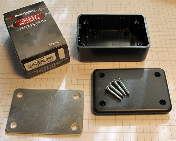
Does anyone have experience or an opinion on putting an EZ Board in a project enclosure box (like the ones from Radio Shack)? I want to protect from damage and dust inside my B9. My thoughts were to cut side vents for heat ventilation. I plan to get as large a box as possible to insure circulation.

Thanks,

Daniel User-inserted image


ARC Pro

Upgrade to ARC Pro

Stay at the forefront of robot programming innovation with ARC Pro, ensuring your robot is always equipped with the latest advancements.

#1  

You could drill some breathing holes and put one or more fans inside or outside of the box.

United Kingdom
#2  

There have been discussions about similar in the past. The waterproofing of it it discussion may be of some use.

The main concern would be the heat generated by the regulators and even if it's not much it will all mount up.

Add in some vents and a fan and it should be good to go.

Better yet, the EZ-Case 3D Printed case may be just what you need.

#3  

@Mulberry , what kind of project are you doing? Are servos going to be connected to the EZB?

#4  

Thanks All

Hi J. It's a life size B9 robot from Lost in Space. The unit has several servos including some strong ones powered by 12 volt batteries so I'm using Pololu H-Bridges. I'm now considering simply a cage of sorts to avoid damage. Perhaps a mesh desk organizer flipped over (see below) and a fan as Rich recommends. The various robot sections are quite cumbersome when you move them about so I need something to protect electronic components.

Daniel

User-inserted image

User-inserted image

#5  

A metal cage might act as a faraday cage and block the Bluetooth or WiFi signal (depending on if you are using a V3 or V4 board). I would stick with plastic.

I think you will be fine if you cut some vent holes in a plastic project box, and mount in a low voltage fan like a CPU fan.

Alan

#6  

Good point Alan.

Thanks,

Daniel

#7  

Small cardboard box with vent holes? Just an idea. Any which way that's a cool B9.

#8  

Thanks Technopro. He's 98% complete now. That photo is about a year old. I have one EZ board currently running the lower section and will use another for the upper section once the new boards start shipping.

Daniel :D

#9  

Final Solution.

So I took a 6 x 3 x 2 Radio Shack project box. Flipped it over and mounted my EZ Board on the inside of the lid. I then cut the side panels out of the box itself leaving the four corners with their screw mounts.

Safe, secure and well ventilated.

Daniel cool User-inserted image

User-inserted image

User-inserted image

#10  

Nice EZ-B cover. It beats an exposed EZ-B getting something dropped on it or what ever could happen while its in a bot or even on a desk.

#11  

@Daniel, Nice looking B9. I haven't had the pleasure of seeing your big guy all grown up and put together. You've only sent pics of a part or two.

I mounted a small fan and pointed it at the regulators on my V3 EZB. I found they didn't really heat up all that much so I removed the fan and cut down on some of the noise coming out of my B9. I know the new V4 will not have regulators so I'm not sure how hot it will get.

Just wondering; what kind if damage could you expect with the EZB being inside of the B9?

#12  

@dschulpius , the ezb v4 should really not generate any significant head. The onboard regulators are to power the processor and the WiFi modules only. There is very little current used by the onboard equipment. The only concern you may have is if you are running several high torque servos. If you are running 5 or more high torque servos then I would consider using external / direct to battery power wire. This is because the current is traveling through the tracings of the board and there is a reasonable limit. I would estimate that at 5 amps.

#13  

Thanks @Josh, I kinda felt that was going to be the case. I'll be using mostly external power for all my servos and will feed the new V4 EZB's I have coming externally also with 12vdc. However I will have to regulate a few small boards and sensors currently needing 5vdc being fed from the V3's I have installed now and will be replaceing. I know the new V4 will feed through the 12vdc I will be powering it with and that will go straight to the current components that will attach to it needing 5vdc. I feel Daniel will have to do this also when he receives his V4. I think I remember him saying he'll be running a V3 & V4 in his B9. Am I right @Daniel?

So bottom line is the new V4 EZB shouldn't have a heat issue.

#14  

Hi Dave

I may just use two V4's in my B9 rather than a V3 and V4 (I have 3 V4s coming). That way the components are all the same, especially with the control graphics.

Quick question though. You say above:

" I know the new V4 will feed through the 12vdc I will be powering it with..."

Are you saying the V4 eliminates the need for an H-Bridge?

Regarding potential damage: I just want a bit of protection as I move components about plus my son tends to get over zealous with his basketball in the garage.

Daniel :P

#15  

@Mulberry The EZB4 will run off of voltages between 7 ~ 17V or somewhere around there. The H-Bridge is used to control and drive motors only. The EZB board cannot drive 2 wire motors directly... You will have the power, but you can't control them with PWM... So you will need a motor controller (i.e an H-Bridge) if your project is using any DC motors... 3 wire Servos can be controlled directly from the EZB4 board (provided the voltage is within the spec of the servo)...

#16  

Thanks Rryerson

But it does not mean a 12 volt servo could be wired/powered directly through the new board, correct? Currently I use an H-Bridge to prevent damage with my big servo with a separate power source. It lifts a lot of weight.

Daniel

Canada
#17  

Looks great Daniel! The v3's need sweet cases too :)

United Kingdom
#18  

Wow, loving the B9:) Can't wait to see more of it!

Like what you've done with the v3 case too.

#19  

@Mulberry A 12V servo will work just fine if your input voltage to the board is also 12V

#20  

Hmmm. I thought the V3 couldn't handle 12 volts and an H-Bridge was needed to prevent damage when reversing the current. I say this because I blew-up (literally) a battery pack when I was messing about with a large servo. I didn't have an H-Bridge and when I stopped and reversed the direction the thing went boom (acid everywhere). Cool to see....after I calmed down

Daniel :D

#21  

I was talking about EZB4 where the board throws input voltage to the pins (no 5V reg on board for accessories)... If you use 12V to power the EZB4 board 12V will come out on the pins.. Powering a 12V servo no problem... EZB3 as I understand it has an on board 5V reg so pins have a max voltage of 5V...

#22  

Daniel, keep your H-bridge setup just as you have it. It makes reversing the DC motors simple and does provide protection if it has it built in. Some H-Bridges do, some dont. If you read the spec sheet on the web site where you bought yours at you will see your does provide reverse current and over voltage protection. That will protect you to a point but if you feed more current (amps) or voltage back into the h-bridge it will fail. Or worse, you could get a chain reaction allthe way back to your EZB. H-bridges are the way to go for reversing DC motors.

Also remember we are talking about several things here; Voltage, Current (amps), V3 EZB and V4 EZB.

V3 EZB has on board regulators that will power servos and other things at 5vdc from the power pins of each port. They will give you 5vdc no matter what voltage you power the board with. Each port has 3 pins; 5vdc, ground and signal. You get your 5vdc power to run servos and other things by hooking up to the 5v & ground pins. You can only pull up to 5 amps (current) total from all things powered from the V3 EZB. The 3rd pin (the singnal pin) also provides 5vcd but is not rated to provide any current (amps) draw. You cant power anything from this pin. It's just used to send signals to turn stuff on and off like servos. It does other things too but I wont get into that now.

V4 EZB will not have any voltage regulators on it. What ever voltage you power the board at will directly feed to the power pin (the old 5vdc pin) of each port. From what I hear you cant pull more then 5 amps total from anything or all that is powered by these ports. I'm not sure what the power min/max is for the V4 EZB but the V3 accepts between 5vdc and 17vdc (I could be a little off here. Please check for your self). ;)

Hope this helps, Dave Schulpius

#23  

Yep. It does help Dave.

Thanks,

Daniel

United Kingdom
#24  

@Dave Just to confirm, you are correct with the V3 voltages. I would say that the V4 probably is going to be around the same as it has an onboard regulator for the 3.3v circuit.

The amount of current the V4 can handle will ultimately come down to the PCB trace thickness, widths and lengths which are unknown so I wouldn't like to hazard any kind of guess.

#25  

@Rich, Thanks for keeping me honest. I was pulling all those values for the V3 EZB from memory After reviewing the help section it looks like I got the port voltages right;


Peripheral Power
Each type of port (Digital/Analog/i2c) include +5 and GND pins. The +5 and GND are powered of the 5 Amp DC Regulator which are protected by the heatsinks. The power pins of the EZ-B can power small motors and servos. The heatsinks will get very hot when more power is used by the peripherals.

The Signal pin is connected to the EZ-B Microchip for reading or writing data from Digital or ADC. (my own voltage testing shows me it supplies 5vdc and it's been well documented that it will support next to nothing in current draw). 

From the online EZB manual:
The EZB requires a minimum of 5 volts DC. The ideal voltage is 7.2 volts. Consult the end of this document for maximum voltage specifications *Note: The higher the voltage, the hotter the regulators will get!

From the end of the above referred to document:
Input Voltage (min) - 5 Volts DC
Input Voltage (max) - 17 Volts DC
Input Voltage (recommended) - 7.2 Volts DC @ 3 Amps

From above it looks like I was right about V3's input voltage. I stated: Min 5vdc and max 17vdc. However thanks for helping me to keep it factual. ;)

Here's a link to that online V3 & V 2.1 manual: synthiam.com/Manual/EZ-B%20Technical%20Manual.pdf

It's very true when you imply that V4's true specs are mostly a mystery to us till it ships and a manual is supplied. confused