
sampaano
USA
Asked
Is it possible to connect a motor shield like an Arduino A000079 Motor Shield to the iotiny to control a pair of DC motors? If so, how would it be wired?
Related Hardware (view all EZB hardware)
EZ-B Iotiny
by EZ-Robot
Control IoTiny with Synthiam ARC: 100MHz Cortex‑M4 Wi‑Fi IoT/robot controller-camera, servos, ADC, I2C and digital I/O for easy internet automation
Wi-Fi / USB
Servos
8
Camera
Audio
UART
✕
I2C
ADC
✕
Digital
✕

Hey, you can upload the Firmware to connect ARC directly to an Arduino...I guess thats the easiest option!
Hi, good luck EzAng
@Ezang:
Please stop spamming ! Can you please explain how your answer helps answering the user question:A000079 Motor Shield documentation: https://store.arduino.cc/usa/arduino-motor-shield-rev3
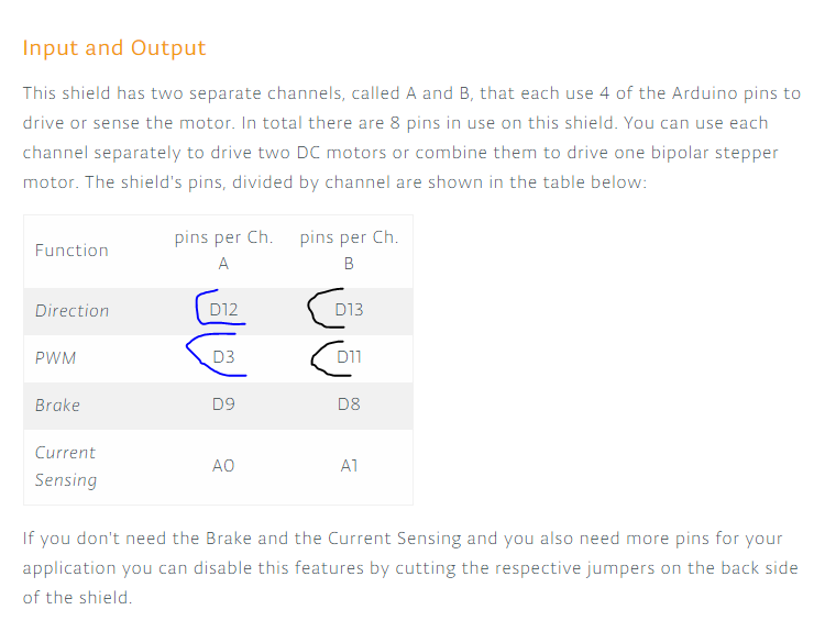
You need to connect: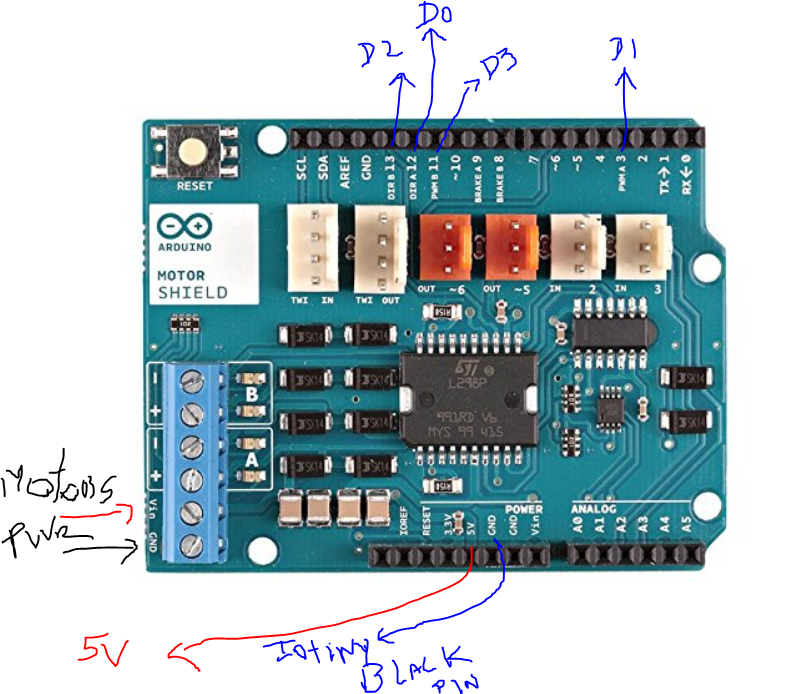
Shield D12 - Iotiny D0 Shield D 3 - Iotiny D1 Shield D13 - Iotiny D2 Shield D11 - Iotiny D3Plus you will need to connect: Shield GND - Iotiny Black Pin (GND) The shield requires 5V to operate the circuits logic (not the motors), and sources from the Arduino 5V shield.
Out of the box the Iotiny has a stable 3.3v :
looking to the shield schematic: https://www.arduino.cc/en/uploads/Main/arduino_MotorShield_Rev3-schematic.pdf
uses L298N: https://www.sparkfun.com/datasheets/Robotics/L298_H_Bridge.pdf
The L298N accepts 3.3 v, but the shield is built to source 5V from the arduino board.
you have three options:
This is only the wiring part, to make it work you will need to use custom Movement panel.
PTP - so does this hbridge work by having the direction true (forward) or (false) reverse? And to stop, simply stop the PWM?
yes it similar to this one too: https://www.dfrobot.com/product-656.html https://image.dfrobot.com/image/data/DFR0004/RoMeo%20V1.1%20sch.pdf
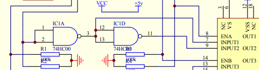
basically they use a single pin (dir) and nand circuit to generate two different signals with opposite values to control the in1 / in2:
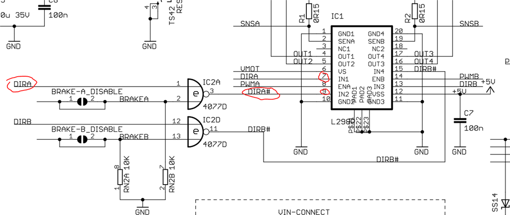
and the PWM 0% to stop moving.The brake pins are used to send HI/HI or LO/LO to the IN1/IN2 that forces the H-Bridge to block the coil movement, so is an active/energized brake.
*** Wrong check the next post ***
The previous post is incorrect, I was in a middle of something, to clarify:
the truth tables:
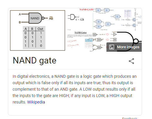
The truth tables are not the same. The arduino motor shield uses a XNOR (4077D): https://www.ti.com/lit/ds/symlink/cd4077b.pdf but in the schematic is displayed as NAND (not correct):the dfrobot uses a NAND gate:
and is correct they use the NAND as NOT gateWhen i did the the post i look the nand symbol and following theirr implementation logic (XNOR) i assumed a NAND and XNOR produce the same output.
They used the wrong symbol for the 4077D ic.