smiller29
USA
Asked
— Edited
MRB1 (My Robot Buddy V1) Project
Welcome to my MRB1 (My Robot Buddy V1)
I have removed the post because it was corrupted somehow and all the pictures and formatting was lost.
This post needs to be deleted.

This forum seems to not let me post two links in the same post for some reason. Here's the Castle programing Kit link: Castle Link V3 USB Programming Kit
Dave, you did post both links. You just accidentally posted the second link at the top of the response
@Monterdur I made these. Here are the two versions I have attached the Left side to make the right just mirror it.
Sensor L_Plate.stl
Solid L_Plate.stl
@Dave Schulpius you can use larger magnets if you need to. The sensors below are simple to use you supply 5v and one pin is signal they also have an LED that shows when triggered. Using these small magnets have the sensor and the magnets about 5mm apart with thin layers of plastic between them and they work with no issues. You just need to make sure the correct poll of the magnet is facing the sensor for it to trigger.
The Buck converter does not require much current at all to operate this circuit. I not sure if I am going to stay with 12V for the motors or go with 24V so I can get max speed and torque out of the NEMA 17's I am going to see if 12V gives me what I want but this change should not change anything else.
It should noted that you can drive like 5 NEMA 17 motors at once at max speed and load on less than 2.5 amps at 24volts.
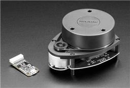
Hall effects 3x1.5mm disk Magnets
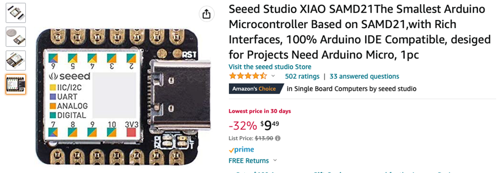
Just another note I love this little package so far it has worked really well. Here is the link to it.Amazing 3D design work smiller thank you very much. I am a newbie and I have a silly question . If I am planning on building my InMoov with an EZ-B V4 do I still have to hack the shoulder and elbow servos? Not hacking them would only limit the rotation of the arm and forearm correct? I notice when I hacked a few servos they all move according to the potentiometer. I'm having a bit of a hard time understanding how when I move the potentiometer slightly to the right the servo turns to the right without stopping. It only stops when I bring the potentiometer back to the center (neutral) position. So when the shoulder potentiometer moves the arm up what is stopping it from turning once the arm reaches it's full arm extension? The servo is no longer programable you are at the mercy of the potentiometer if I am understanding it correctly.
@Monterdur, I understand where you are at I was in the same place when I started my project. This is what helped me get a much better understanding of how to make things work. I found some really good video sites that can really help you on this project and if you have not seen these them I would recommend you check them out.
Steve Rayner Cyber_One Kyle Campbell To answer your question yes you are going to need to remove the pot and the stops in the servos so they can rotate 360 degrees.
When you relocate the pot and set it position it will control the starting and stopping point of the servo. Think of it this way if you say urn the pot all the way counter clockwise the servo would be stopped at zero degrees if you turn the pot half way the servo would stop at 90 degrees if you turn it all the way clockwise it would stop at 180 degrees note most servos that say they turn 180 degrees don't really have that range of motion. If you put a servo horn on a servo you can see how this works if you have a servo tester.
This is very good information smiller. Thank you so much. I have not seen any of these videos. I have a lot of very interesting homework ahead of me. Your description is very clear and makes sense. I now have a good approaching point thanks to you. Many thanks smiller.
Just sitting here watching TV with the wife and thought of another new shoulder design that would be really cool but I would have to make a completely new torso and neck for my inmoov build.
Maybe at some point I will build a new remixed Inmoov highbred with some of these concepts that pop into my head.