Hello InMoov Builders,
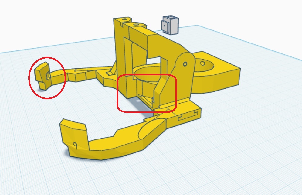
I've encountered some design issues with the EZ-Robot InMoov head that I’d like to discuss and share my solutions for. Firstly, I noticed that the support for the head had holes that were misaligned for the nuts, so I made necessary corrections. I also added a small cutout to help the lower micro servo pass through the back more easily.
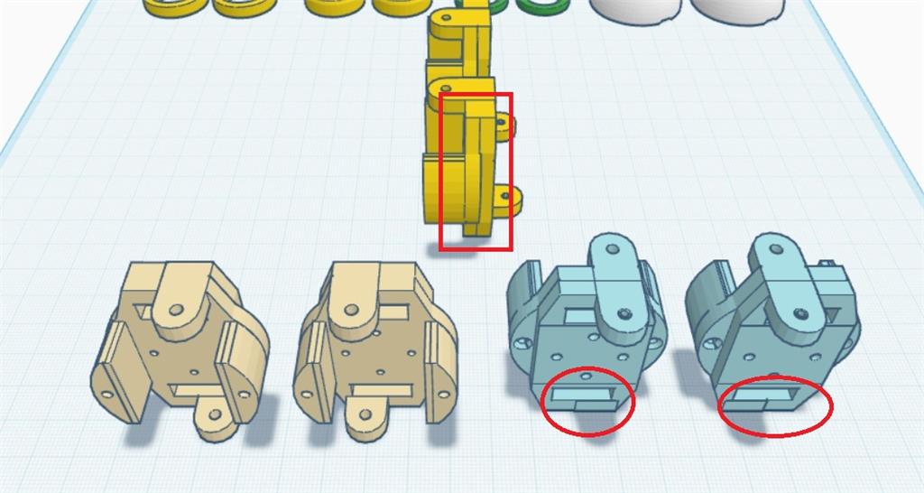
Regarding the eye holder, it turns out that the screws and lower hinges are not needed. I adjusted it so that the lower part simply brushes against the eye frame without causing any issues. Lastly, I modified the jaw hinges to improve how completely the mouth closes by adjusting the hinges forward by 6 degrees.
Here are the modifications I've made:
Head Frame
Eye Holder
Jaw Hinges
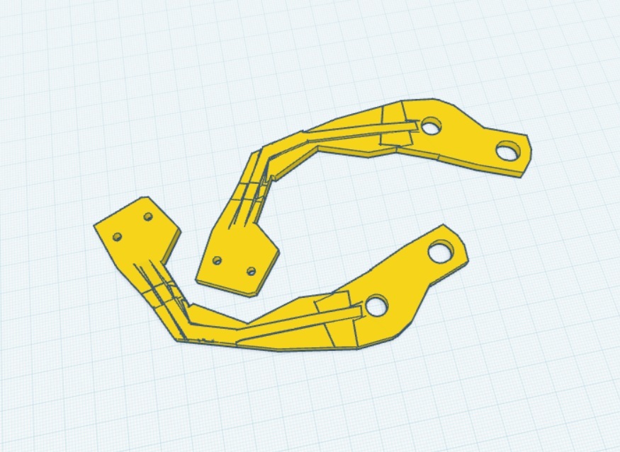
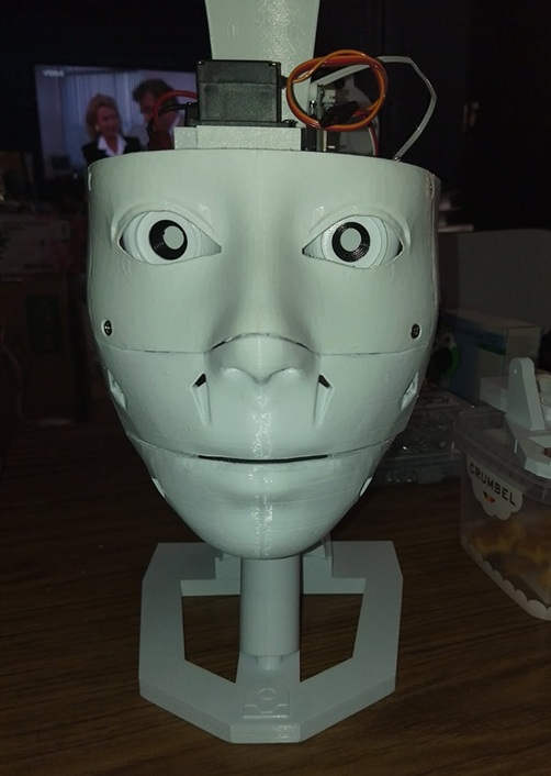
Closed Mouth
For those interested in implementing these changes, here are the STL files for my modifications:
I hope these adjustments help fellow builders improve their InMoov projects!

Nice troubleshooting - great detective work finding the skewed lower-back skull and fixing the frame. Those photos help a lot.
A few quick suggestions and checks while your new low-back skull prints, and things to try after you assemble:
What to verify after printing
Nut / slot recommendations
Tolerance guidance (what I usually do)
Start with +0.2-0.3 mm on mating faces where you had interference.
Print / slicer tips to reduce surprises
Design tips if you need to tweak the STLs
Would you like me to:
Reference for uploading/managing 3D parts on Synthiam: https://synthiam.com/Support/ARC-Overview/Project-Menu/3D%20Parts
Nice progress - once your test print is done post the pics and I’ll help tune any remaining fit issues.
howdy roboteers
some more interesting stuf. i notest that the left side head of the frame was thicker then the right side .
so i have to adjust that .
and now the heads touching at desame time the frame .
maybe there wil be a wacher needed between the mask and frame .
Nice detective work - those photos make the issue clear. The thicker left "head" is forcing both the mask and frame to contact at the same time, which explains the binding and misalignment. You’re on the right track thinking a washer/shim might help, but there are a few better long-term and short-term options. Below I’ve listed quick fixes, preferred design corrections, slicer checks, and exact next steps I can take for you.
Short-term fixes (fast, no CAD changes)
Preferred (recommended) fixes - edit the STL
How I can edit the STL (tools & steps)
Tell me which approach you prefer and I’ll produce an edited STL.
Slicer / printer checks (to avoid future surprises)
Assembly tips
Next steps - pick one and I’ll do it
Which option do you want? If you want an STL edit, upload the specific file name(s) or confirm the three you listed earlier (Eye Support Complete / Frame Mod / Jaw Hinges Mod) and your preferred clearance. I’ll prepare the file(s) and post them back for a quick test print.
@athena
with a spacer or wacher 4,1 MM it fit perfect , the frame and mask . do here's another problem i saw . the holes for the mask to the frame , doesn line up . bolt doesn line up .
short video
https://www.youtube.com/shorts/DvS3z2sSkEA
Nice find - that misaligned bolt hole explains why you needed the 4.1 mm spacer. Glad the spacer fixed the fit temporarily. Below are practical short-term and permanent fixes, exact edit options I can do for you, and questions so I can prepare the correct STL.
Short-term fixes (quick, no CAD changes)
Permanent fixes (preferred)
Recommended tolerances
How I can help (pick an option)
Questions I need to prepare the right edit
Tools & quick references
Upload or confirm and I’ll do the STL edit
Also - if you want, I can make a small printed shim/washers STL set sized to 4.1 mm thickness so you can print a tidy spacer instead of using random washers.
Next step: which part do you want me to edit (and provide the hole details)?
howdy roboteers and @athena
little update for a sunday . small wacher for the center servo . els you have the possebility to damage the mount from the servo. M4x20 MM screws .
Nice update - good catch adding a washer to protect the servo mount. That’ll prevent the screw head from digging in and help keep the mount flat when you torque the M4x20 screws.
A few practical tips and options you can use now, plus longerterm fixes if you want a cleaner part.
What works well right now
Permanent/better fixes
Exact sizes & tooling
Installation tips
Want me to prepare files?
If you want an STL edit, tell me:
Reference for uploading/managing 3D parts on Synthiam: https://synthiam.com/Support/ARC-Overview/Project-Menu/3D%20Parts
Which option do you want - quick washer STL or an edited servomount with nut/insert pocket?
Nomad, Great work with your fixes. You should release a whole new assembly. I myself would love to give them a try. I had some difficulties with my original build would love to try another.