
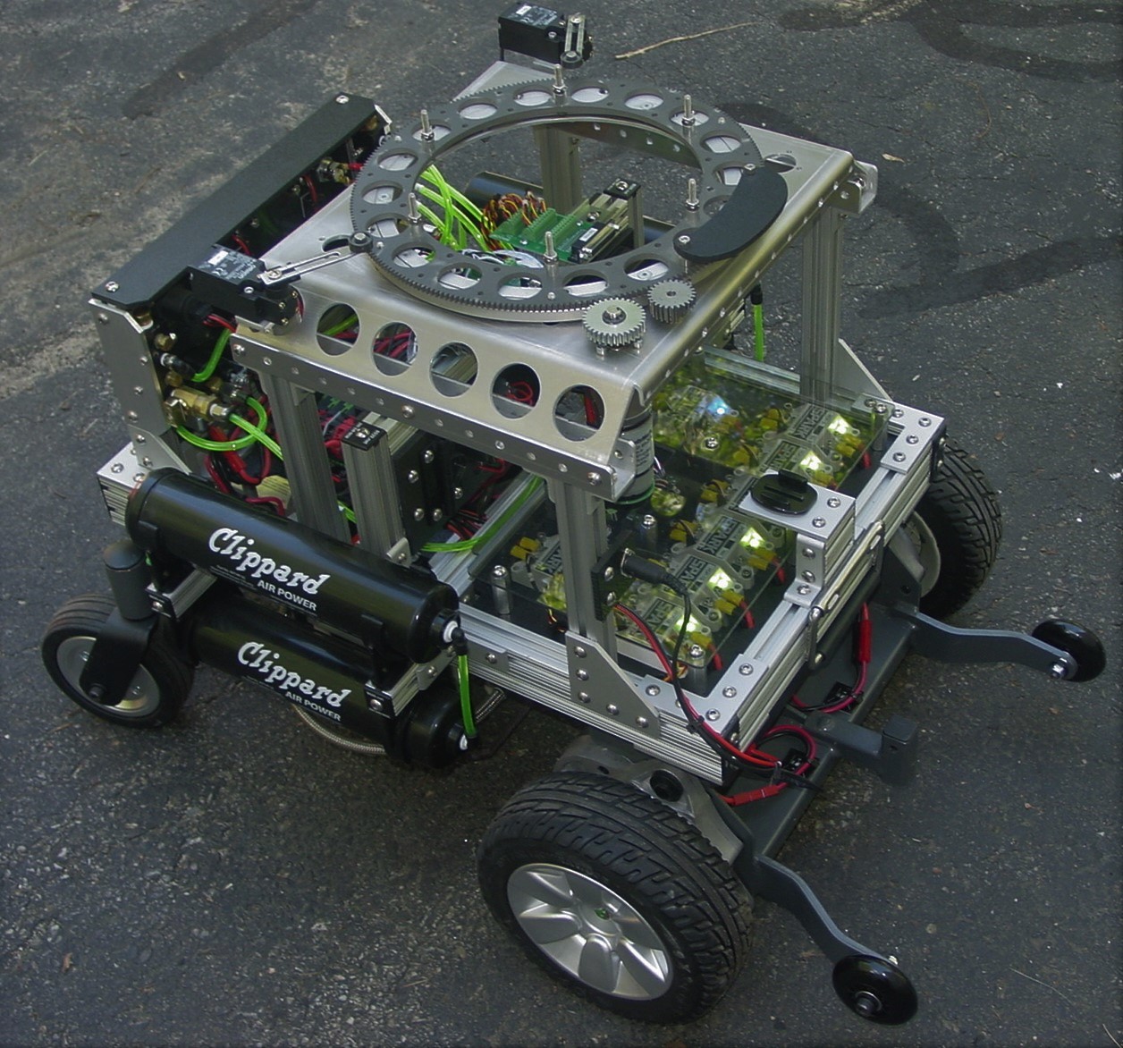
Last fall I completed the ARMadeus Mk. 12 project, the latest edition in a series of large scale robots. The Mk. 12 uses a power wheelchair as the base and includes a new, anthropomorphic personality module. A detailed construction article was published in the November/December 2018 issue of servo Magazine. Once again, ARMadeus was featured on the cover. My design philosophy of making modular robots and subsystems with off the shelf components was implemented throughout every stage of this project.

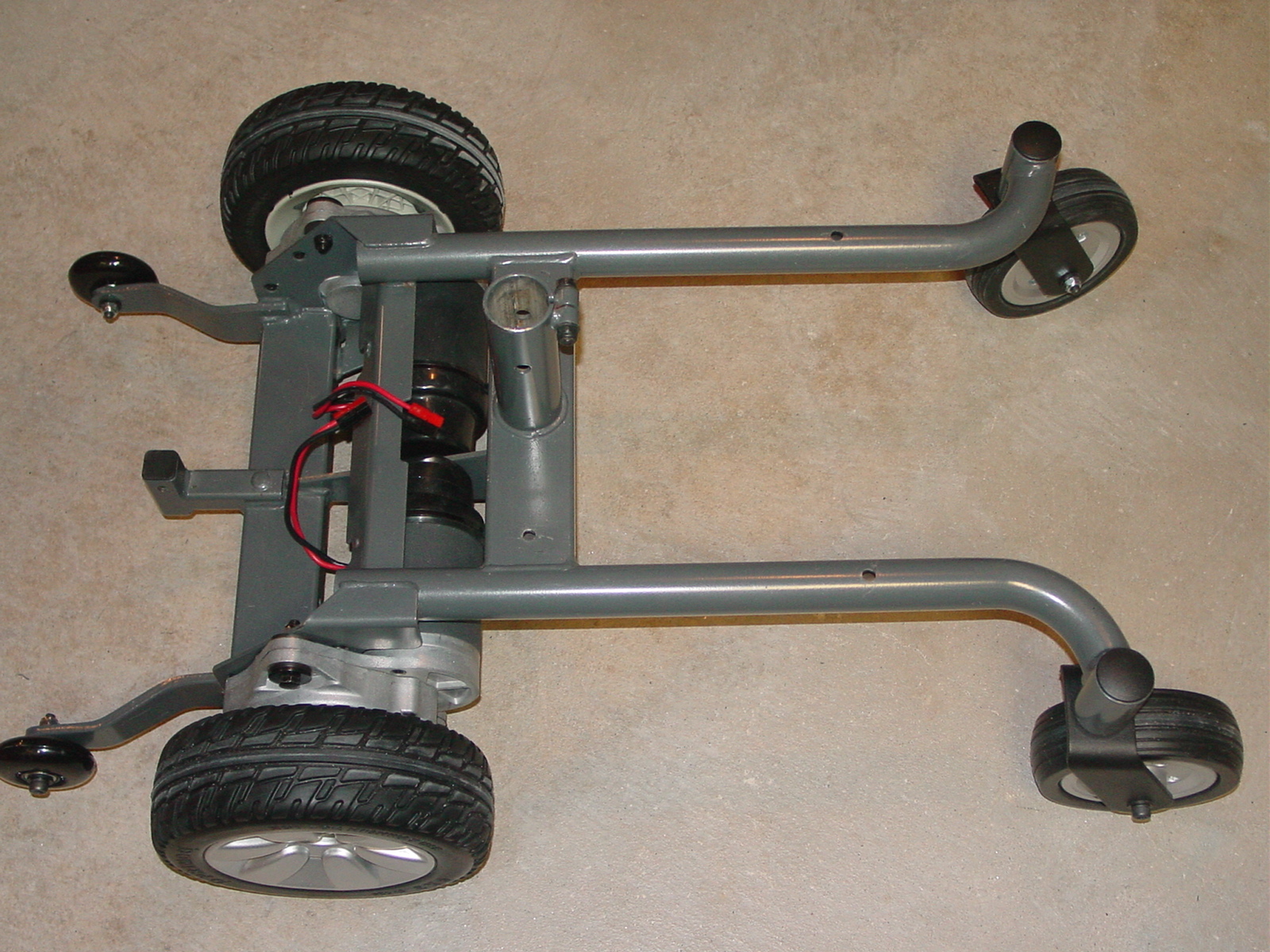
The project started with used parts from a Jazzy Select Elite Power Chair. I had been wanting to do a power chair to robot conversion for quite some time. Finding an ideal frame on eBay was the spark that got things started. Rather than buy an entire surplus power chair on eBay, I bought only the parts I needed, the frame, drive motors, and wheels. Changes to the stock power chair chassis were minor. I removed the electromagnetic brakes from the drive motors and installed 45 Amp Anderson Powerpole connectors to the motor leads. I removed the top 4.5 inches of the seat post tube, and enlarged 4 holes in the welded steel frame for mounting electronics. The assembled power chair chassis weighs 51 pounds and contributes to a low center of mass. This was not going to be a lightweight robot. Since the stock power chair is designed to support a 300 pound load, this new universal robot base should be able to handle anything I could design.
The next step was to construct the control module frame using 80/20 aluminum, T-slotted extrusions. The control module frame houses all the electronic, power distribution, and pneumatic subsystems. It drops onto the chassis and is secured with just four 1/4-20 brass thumbnuts. A lot of thought and effort went into finding suitable locations on the frame for all of the different subsystem components. I wanted the overall design to be as compact and efficient as possible, but still be modular and accessible.

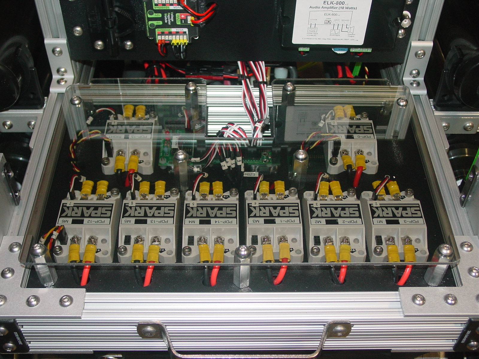
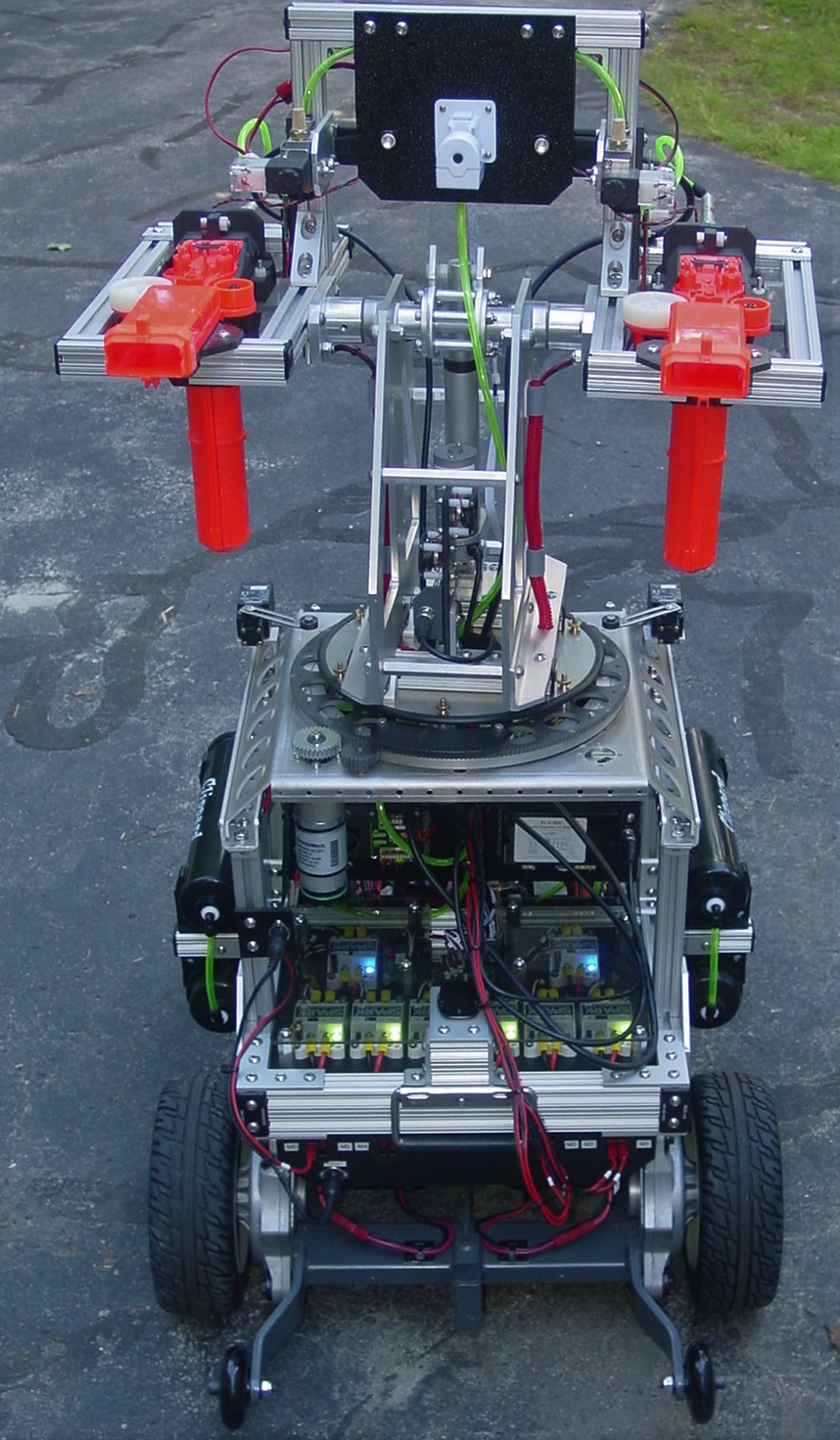
Starting at the front of the robot, the subsystems were designed to be easily incorporated onto the control module frame. Leading the way is a bank of eight SPARK electronic speed controllers, Two controllers were dedicated to the main drive motors, one was configured with limit switches to control the turret rotation motor, while the remaining five were allocated for individual actuators in the personality module. A polycarbonate shield protects the exposed terminals of the motor controller bank.
Next in line was the centrally located, vertically mounted EZB v4/2 controller and associated electronics assembly. One challenge was how to reliably connect the EZB I/O lines to the personality module. Groups of related EZB signals were wired to three, DIN rail mounted breakout boards from Winford Engineering. servo signals were connected to a DB25 board, digital signals for switching LED lights and/or solenoids to a DB9 board, and sensor signals to a DB15 breakout board. With matching breakout boards in the personality module, all the control lines could be routed with just 3 standard data cables.
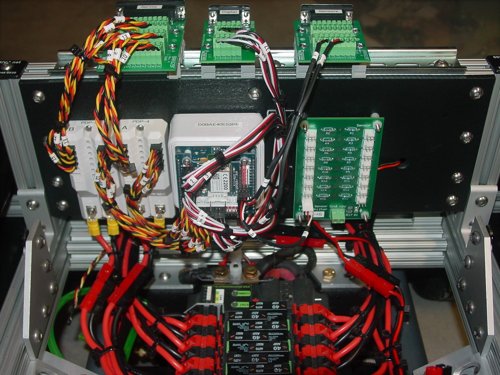
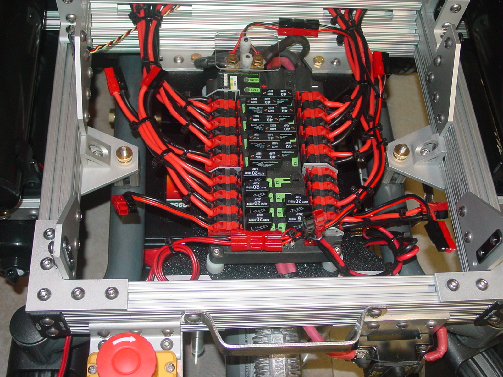
The power distribution panel with circuit breakers for each branch circuit was located directly behind the EZB controller assembly. 12 AWG wire and Anderson Powerpole connectors were used extensively to minimize voltage drops and facilitate debugging. Main robot power is supplied by a 12V/35Ahr battery mounted in front of the compressor, on a 3/8 inch thick polycarbonate plate suspended from the control module frame.
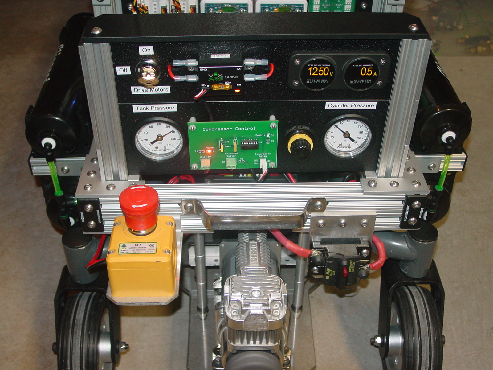
At the rear of the robot, a second vertical assembly contains the pneumatics control hardware. This subsystem design allowed open access while keeping the compressor wiring and tubing as compact as possible.
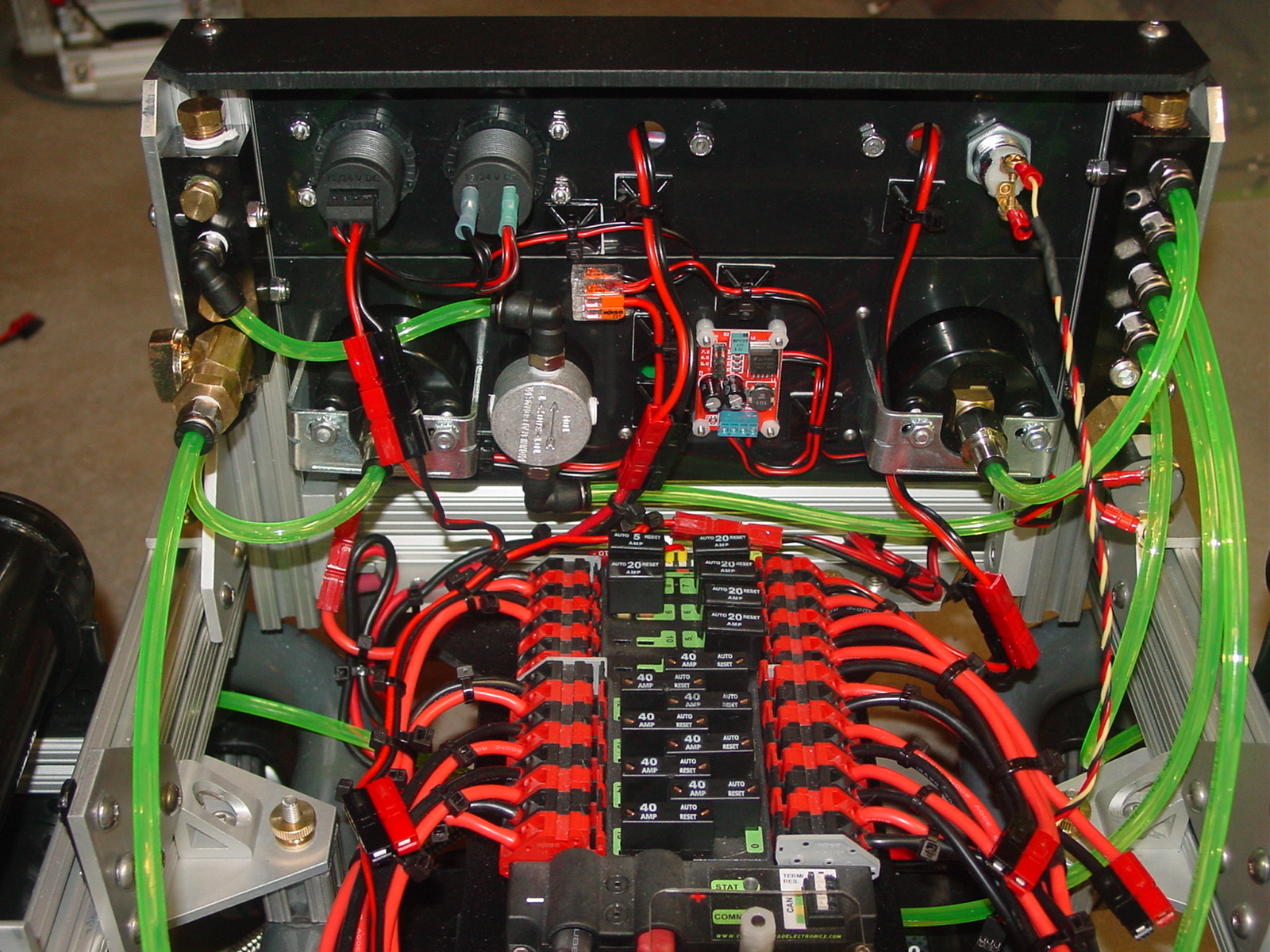
The main breaker/power switch, e-stop switch, drive motor override switch, battery voltage and current meters, and pneumatic controls were installed at the rear of the robot.
The completed Mk. 12 universal base weighs 132 pounds. Using a power chair as the base for a large scale robot was a good engineering decision. The heavy-duty base is stable and robust. Forward/reverse movement is eerily silent. Turning motion is smooth. Even though the 10 pound drive motors were intended to be run at 24 Volts, they are quite content operating with reduced speed and torque at 12 Volts.
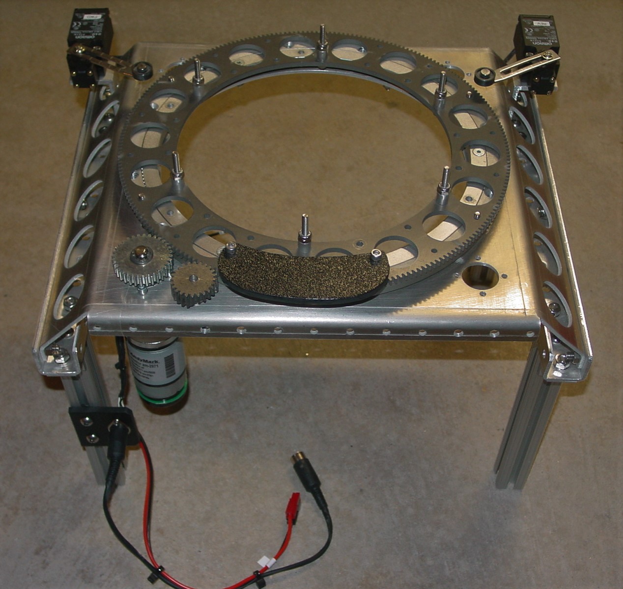
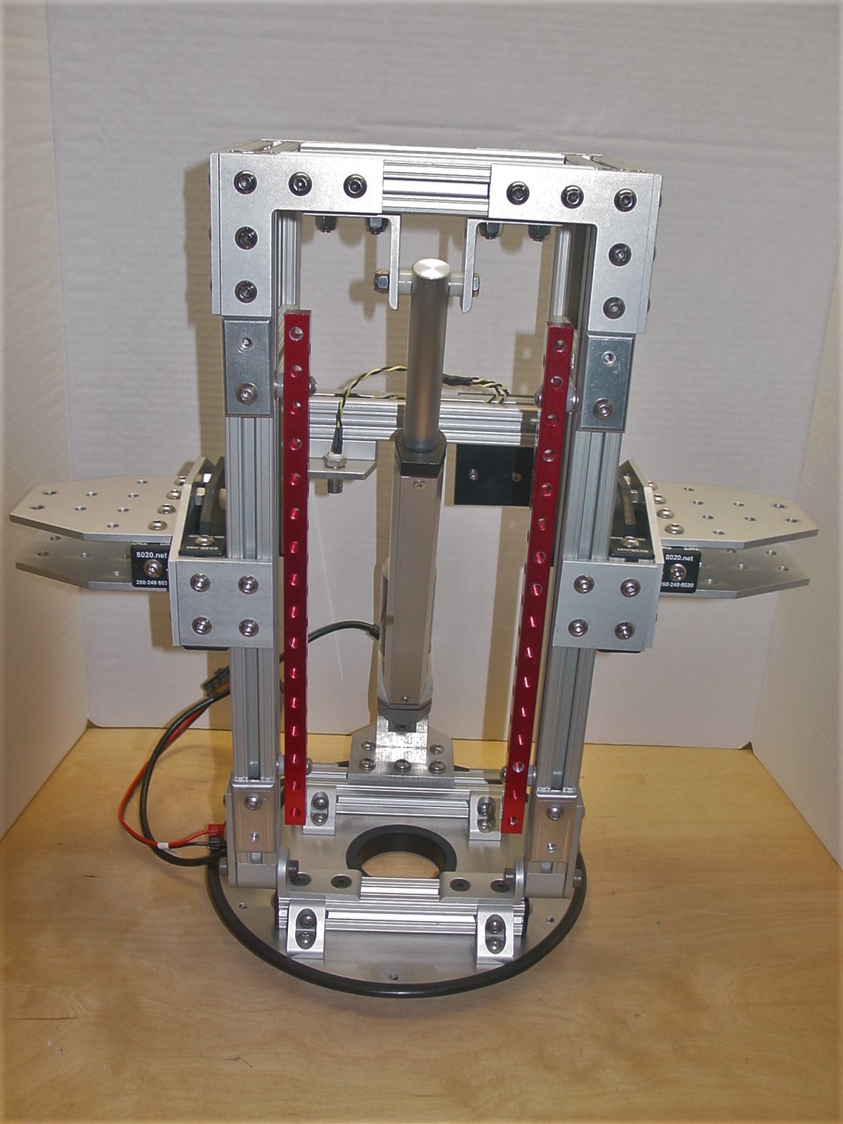
With the universal base complete, it was time to construct a new personality module. Starting with a 10 inch diameter aluminum base plate, the core mechanical component for every personality module, I built a 16 inch tall torso frame. A linear actuator tilts the torso +/- 30 degrees.
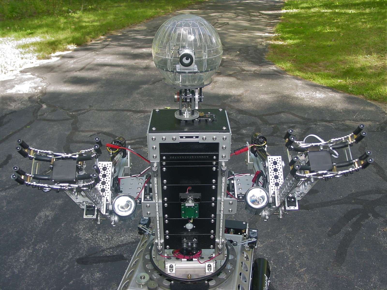
One of the original design goals for this new personality module was to provide a convenient platform for experimenting with digital and analog sensors, Two 12 inch long Nutstrips serve as mounting rails for individual sensor boards. The chest mounted sensor array supports up to 5 sensor boards. The current sensor array is configured with an IR distance sensor, X-Band and PIR motion detectors, and a LIDAR laser rangefinder.
The shoulder blocks on each side of the torso for mounting arms were constructed with standard 80/20 hardware. The modular nature of these blocks permit different arms to be attached to the torso. With all the support electronics already incorporated in the base unit, it would be a relatively simple operation to replace one or more of the Mk. 12 arms with Mk. ll NERF disk launchers, creating a 'Frankenbot' hybrid.
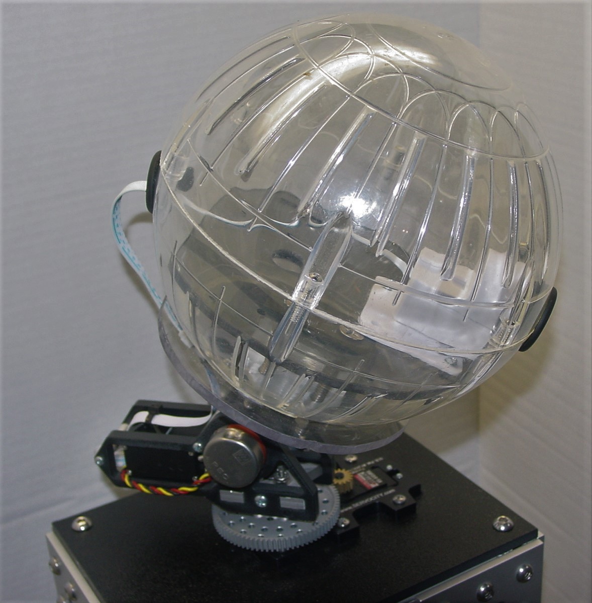
Two servo gearboxes from ServoCity provide the pan/tilt function for the 7 inch diameter, hamster ball, head with an installed EZB Wi-Fi camera. The combination of turret rotation, torso tilt, and head pan/tilt give the camera an exceptionally large viewing range.
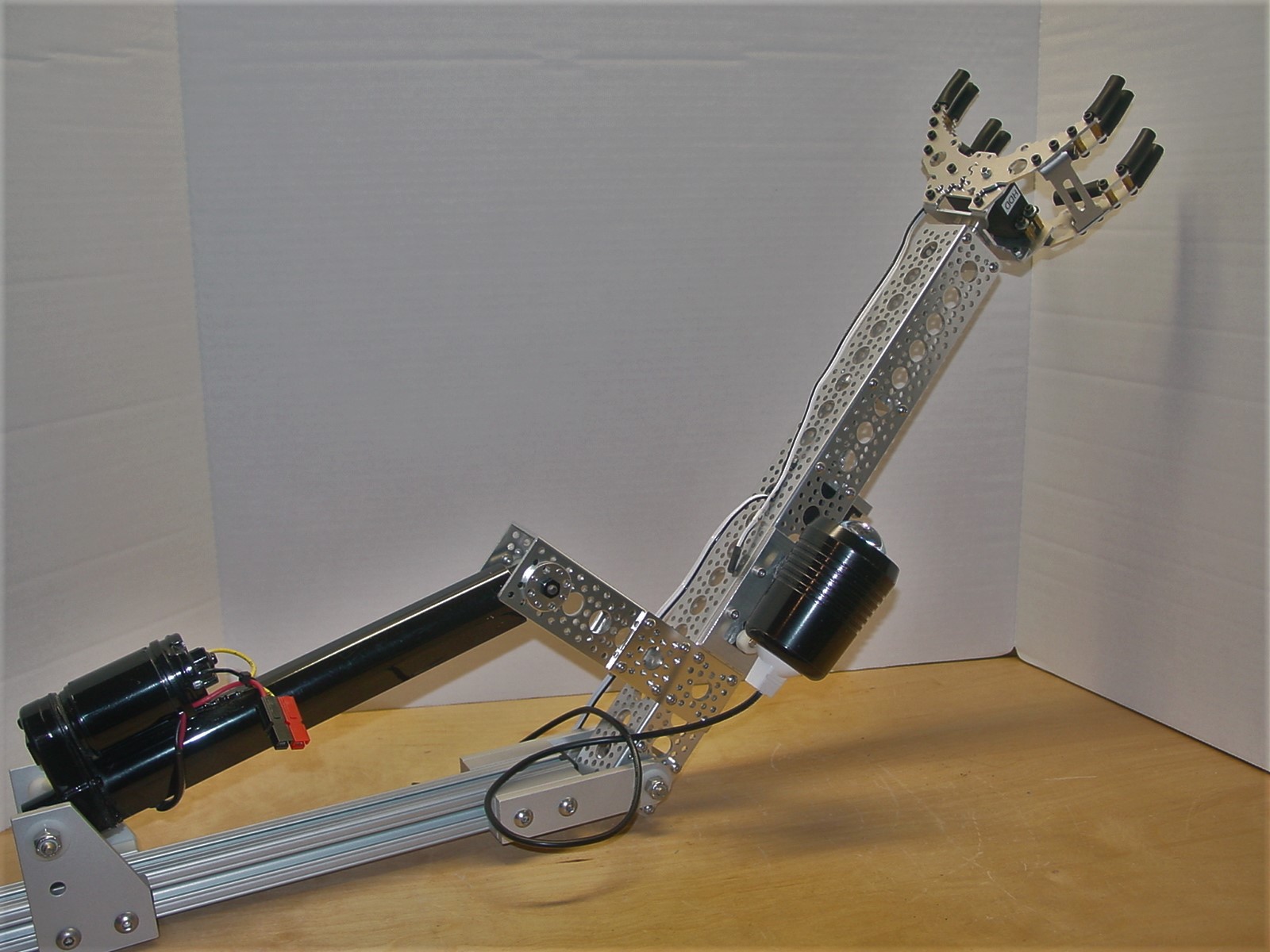
The arms were primarily made with a mix of 80/20 hardware and Actobotics parts from ServoCity. The 15 inch long forearms rotate 90 degrees. EZ-Robot HDD servos in each arm rotate the wrist and open/close the gripper. The grippers were low cost versions I found on eBay. Short lengths of latex tubing on each finger add some useful gripping compliance, while providing some protection from the sharp edges of the stamped aluminum fingers.


A self-imposed, non-negotiable design requirement was that the Mk. 12 base be backward compatible with the dual NERF disk launcher module from the previous Mk. 11 project. With some minor changes to the launch trigger wiring to accommodate the new data cabling protocol, the launcher is a fully operational member of the Mk. 12 personality module family. The second video demonstrates the range of motion and the pneumatic firing sequence in full auto mode. 40 disks launched in under 6 seconds.
No small animals were harmed in making the functional test video. The main drive motors were disabled. A 6 ounce chipmunk vs. a 168 pound robot. You do the math.
I'm satisfied with the design and performance of the redesigned ARMadeus base. I don't foresee any major base development efforts on the horizon. It's taken nearly 20 years to get to this point. After these pictures were taken, I did move the the speakers from the personality module down to the turret frame. Speech synthesis and audio file playback capability are common features shared be all the personality modules. It made sense to keep all the audio hardware in the base.
What's next? I do have some thoughts brewing for a new potential personality module, a single arm unit with extended reach.
Discover more robots
Billderwent's Boris V2

Orwnic82's Ez-B Processor Quadrotor

@Jim Congrats for getting on the cover of Servo! So awesome! Wish I still subscribed so I could have got that issue.
That is a pretty clean robot design, great work! The camera inside the hamster ball is a clever idea, makes it look like a big eye ball
In the video I was stunned by the boldness of that chipmunk, it did not fear ARMadeus at all. Must have been either Chip or maybe Dale. I had a great laugh!
This is amazing!! Super congrats getting the cover of servo Mag - that's a HUGE validation for your project. I can't believe how clean the wiring is on your robot. You know me, everything is a rats nest. To see your setup is just down-right awesome!
What future features are you planning on adding? Anything that you've considered that i can help with? Let us know! I always enjoy the challenge of making a new skill control for ARC.
@DJ Thanks for the favorable comments. With that much potential signal activity between the controller and the rest of the robot wire, management is critical, and definitely worth the effort. No rodents are going to find a home in my bot. The breakout boards and data cables simplify debugging and reduce the chance of hook up errors.
As far as new behaviors are concerned, I do have one wish list item. Unlike a lot of robot builders who use servos for primary locomotion, I use differential drive with electronic speed controllers driving 2 heavy duty dc gearmotors. Unless I'm doing something wrong (definitely within the realm of possibilities), I've never had much success getting true proportional control using my Logitech joystick with a Movement Panel. I get the best results using a standard joystick control by inserting an IMX-1 mixer from RoborLogic between the EZB and the drive motor speed controllers. Speed and turning rate are directly proportional to the analog joystick deflection. It would be nice to have a control that mixes the X and Y PWM signals in a similar manner without the use of an external mixer.
:D Wow that looks Fantastic! I always thought a wheel chair would make the perfect robot and your's is the proof !