Rsp Robot

R2D2

Spain
robot video thumbnail

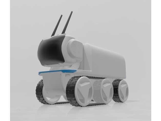
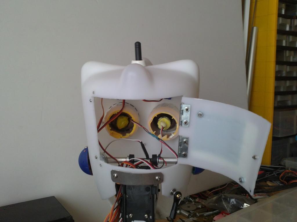
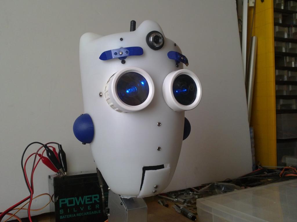
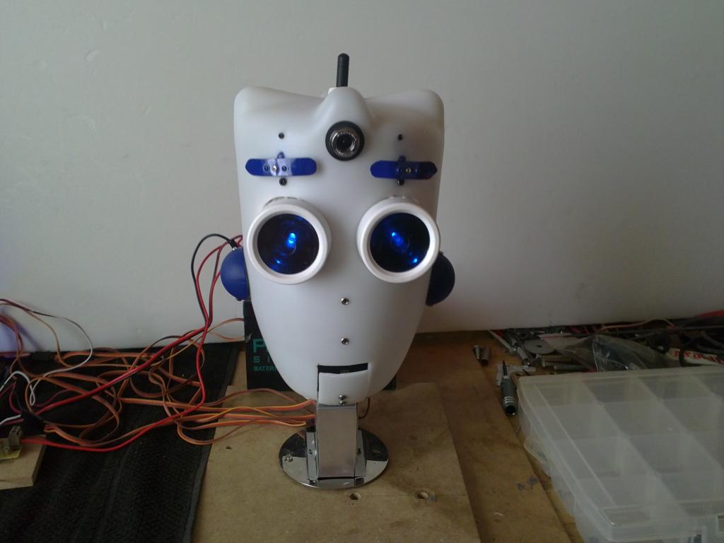
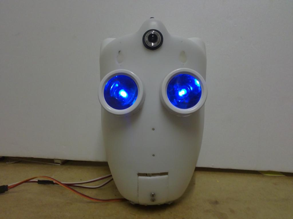
Hi all! I'm excited to share this project with you, this is the robot RSP, I bought my second ez-b (v3) and having checked with my first robot(MY ROBOT) , I decided to undertake a larger project, its height will be of 5.4 feet (1.65 m), currently under construction I have the head, and gathered the materials for the traction system, some voltage regulators, 2 rc esc, several batteries, etc.. I enclose a drawing of how it will look when completed and some photos and video. I hope this project will have a mutual sense of teaching and learning for the entire community that will inspire others and that I may be inspired by all your valuable ideas, more information soon.:P

User-inserted image

User-inserted image

User-inserted image

By — Last update

ARC Pro

Upgrade to ARC Pro

Unleash your creativity with the power of easy robot programming using Synthiam ARC Pro

#1  

Very Cool!:)

LOL, I started Vacuum Forming some custom parts for a Scratch EZB Robot Build as well, with Camera mount and "EYES", similar to yours...lol!:) Very Nice.

#3  

R2D2 thats really cool !:)

#4  

Very cool!) nice work! Reminds me abit of one of the older models from the movie: I-Robot ,,,

Spain
#5  

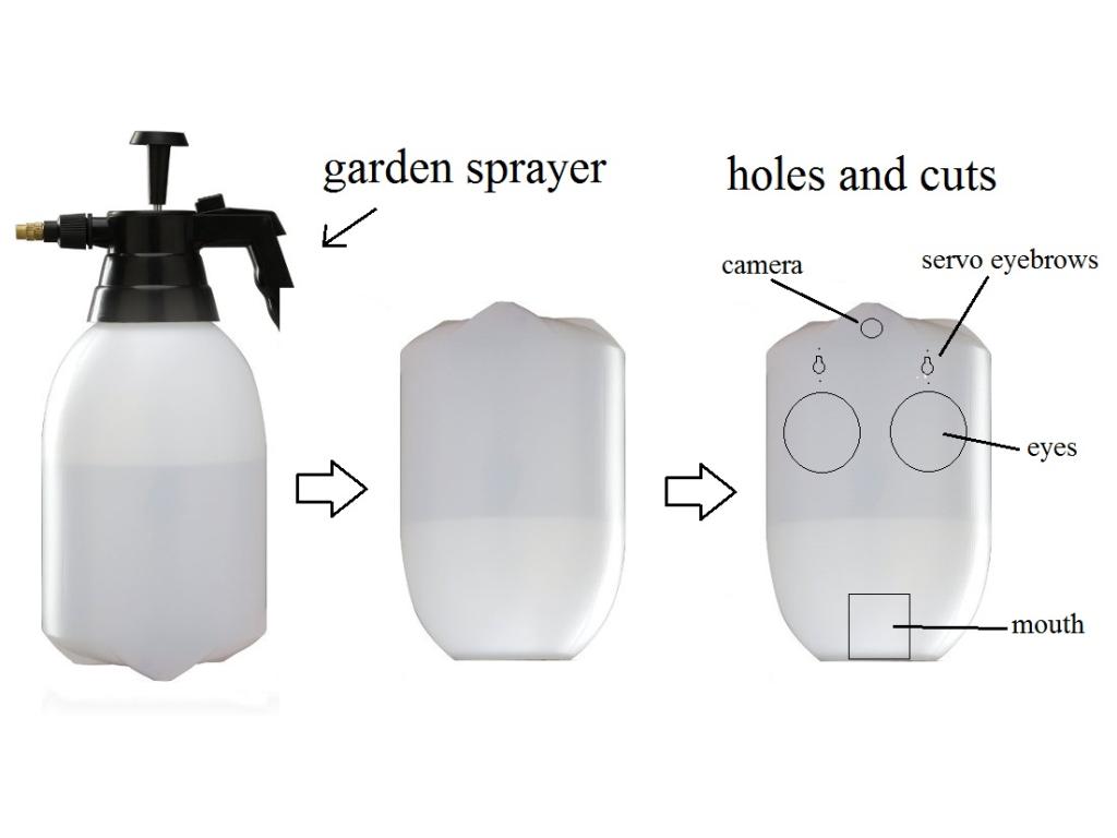
Indeed RR333! the robot from "I robot" has been an inspiration to me, but I do not use titanium to build it, use a sprayer, garden should be recycled plastic and is a very hard blows, but easy to drill.

User-inserted image

;)

#6  

This is so cool! I too am planning on a large bot (after B9 of course) - I will be following your progress closely for ideas and inspiration.

Spain
#8  

Go! few lovers of big robots, I'm glad there's another story for recycling. After searching and searching for a strong traction system, reliable and economical, escontré this: DAREWAY.

User-inserted image

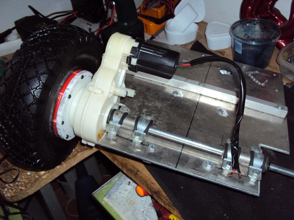
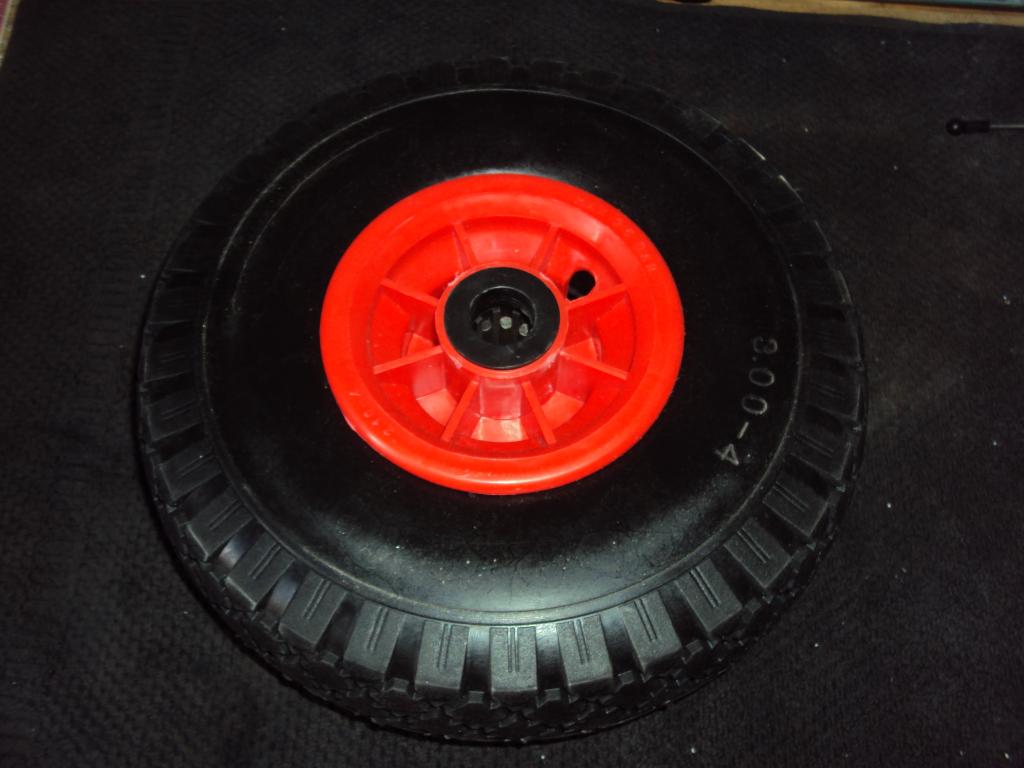
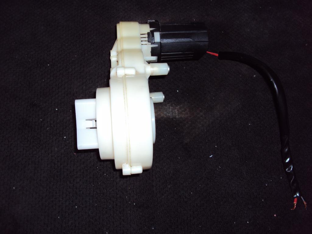
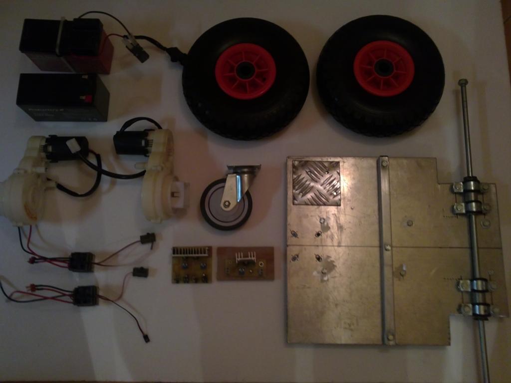
is the child version of the Segway. I could buy one used and extract their powerful engines with gearbox, a 12V 7A lead battery and the axis of the wheels (very important so that the weight does not damage the gear reduction) all riding on an aluminum cut to size. The original wheels were discarded because they were dareway plastic in return bought a wheelbarrow rubber wheels that offer much more grip and traction.

Spain
#9  

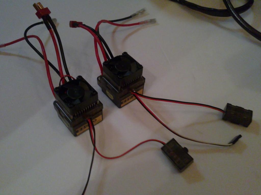
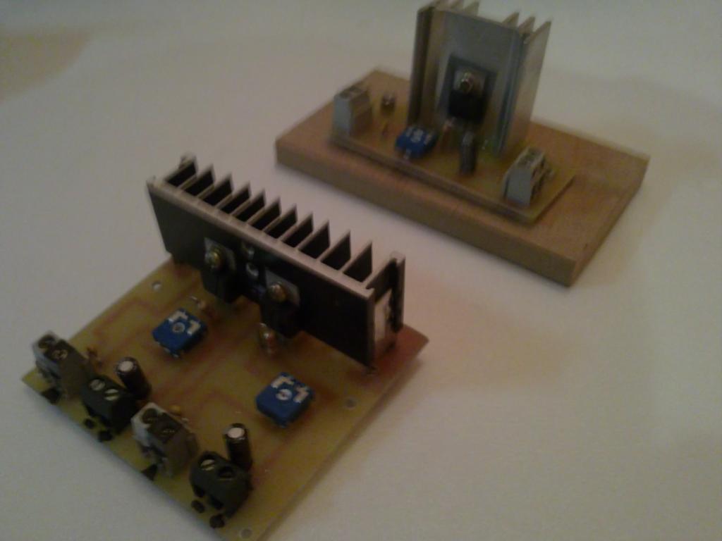
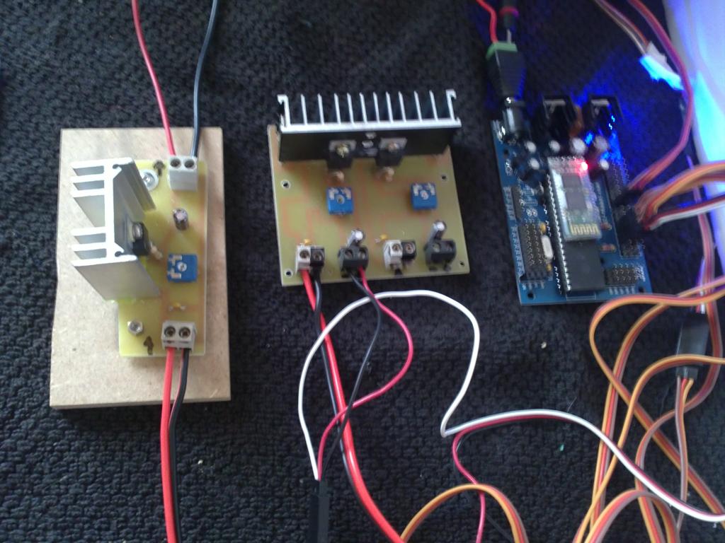
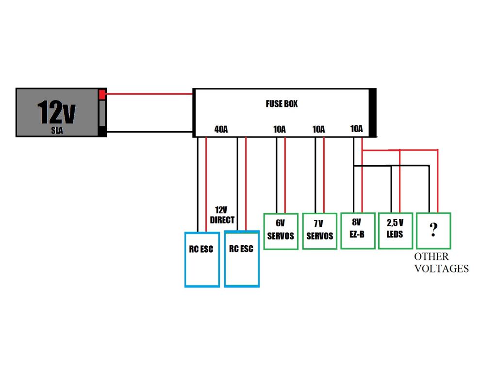
These are the rc esc that I use for reducing motors and voltage regulators also some construction itself for different voltages needed by the robot (LM317)

Motor ESC Electronic Speed Controller

User-inserted image

User-inserted image

I forgot, in the rc esc (important): cut the red wire 3-pin connector and leave only signal and ground, to avoid introducing voltage on the board ez-b.:)

#11  

thats cool man , cant wait to see the body and chassis on this guy

#13  

very nice!

Spain
#14  

A little preview of the project as a drawing.:P

User-inserted image

PRO
Synthiam
#15  

I like this guy sooooo much!!

#16  

@ R2D2:

WOW, what a great concept! You, like myself have, began the constrution of a larger scale robot. You are using componets very similar to what I'm using. Someone else had mentioned a trend towards building larger bots. I will be watching your progress on this build/design. I will be documenting my build (Project Gizmo) progress. I concur with your idea of sharing ideas and building techniques. Very nice concept!!!!!!!

Spain
#17  

botz012248 the documentation of the project believe it is important for growth in the community, absorbing ideas from each other, a big robot controlled by a board so small! that wonderful contrast, and how much free space for wiring! I encourage everyone to build large robots, with the fantastic work of DJ and his team, the increasing accuracy of the software to control servos and other accessories, is easier than ever! My project will not be too quick to finish, I'm expecting a package of $ 150 high-torque servo, which is lost for the last 3 months, communicating with hongkong to fix it. GIZMO also follow your project closely to increase my personal database.

#18  

A robot of that size you should just put a mini atx computer in it with a 12v power supply...... I did it with a much smaller bot.
User-inserted image

#19  

Check out my "Project Gizmo" update in this thread. I've added pics of the finished head. I'm looking forward to seeing your progress R2D2. Again; I concur. DJ has given us so much!

Spain
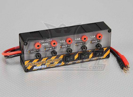
#20  

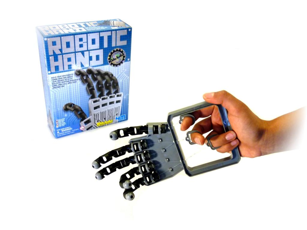
@ Jstarne1: nice mini itx board with a practice video output!. Using another PC for wireless communication, or programs from the PC integrated into the robot?

Australia
#21  

Hey R2D2 your build is looking great,good to see people are thinking out side the box. Quick question what did you use to make the eyes?

Spain
#22  

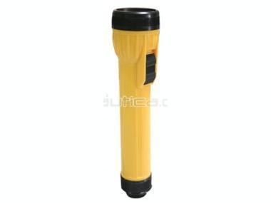
Vettelover, the eyes are two lanterns plastic of 2 dollars, then painted in white, light bulbs are replaced by blue LEDs. I have also used "polarized adhesive", which is used to darken the windows of cars, so that you can not see inside from outside, and blend a little light inetrior, Greetings.

User-inserted image

polarized adhesive

User-inserted image

Spain
#23  

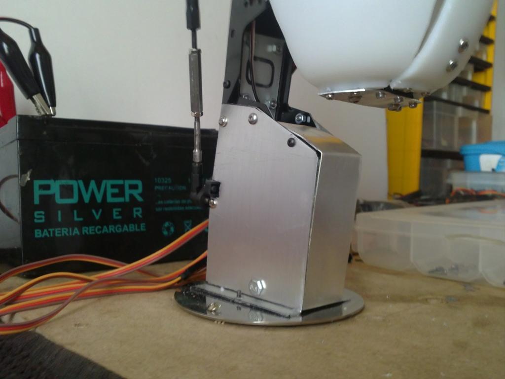
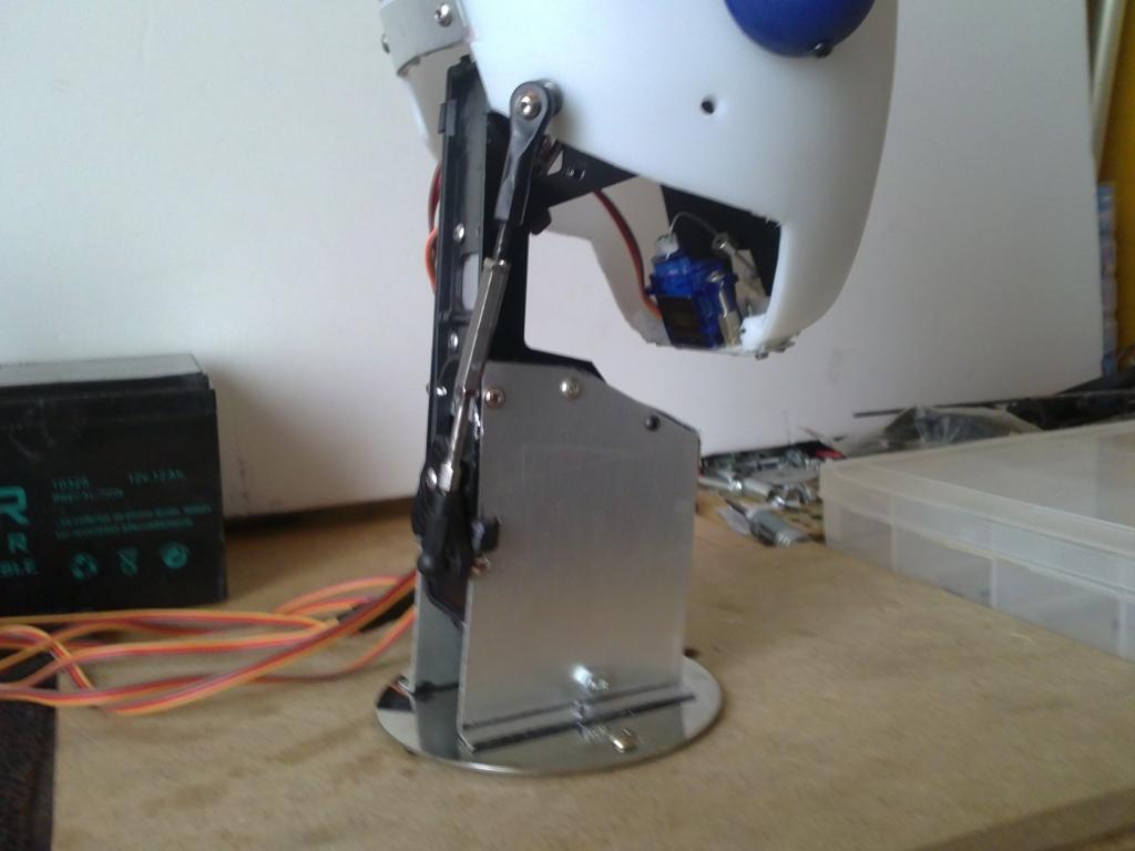
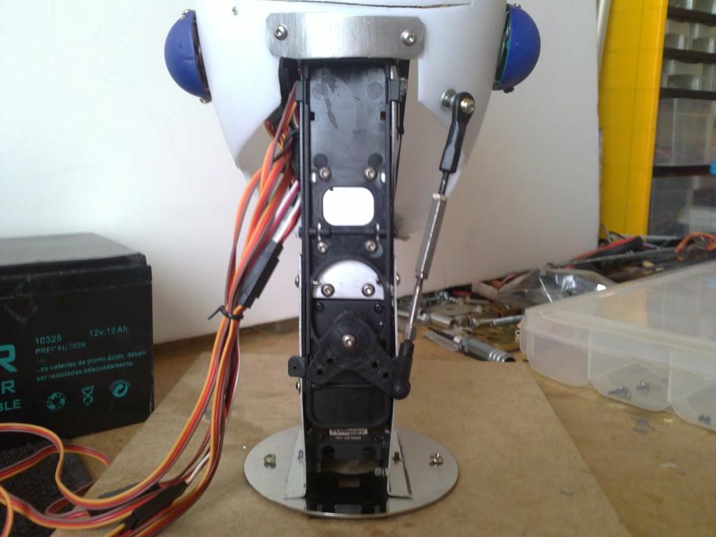
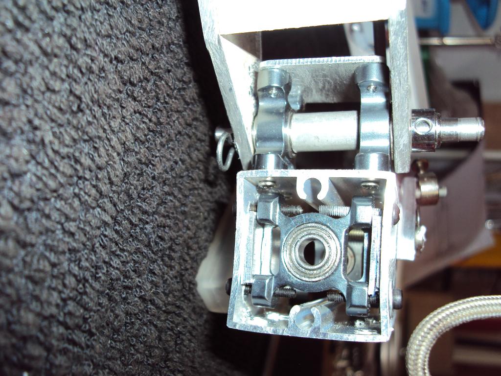
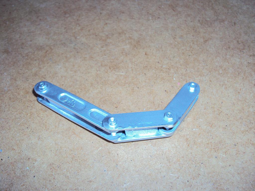
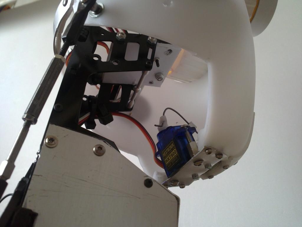
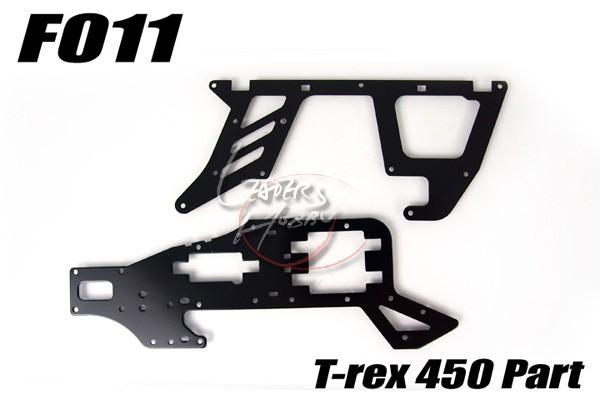
The head is complete and support the neck with his pitch servo. In the construction of the neck I used some materials as a hobby helicopter type chassis 450, a shaft support bearing rc car, steering gear arm rc car for the pitch axis, helicopter screws, aluminum foil fine and a plate of computer hard drive. By this I mean that robot builders can adapt our needs to pieces that already exist in markets and thus relieve rc lot of work in the manufacture of our parts.:D

User-inserted image

User-inserted image

User-inserted image

User-inserted image

User-inserted image

United Kingdom
#25  

Scary good R2D2

Steve_C

#26  

Dude!, I'm Freaking Out at how Cool this is!!!! Nice Work!:)

Spain
#27  

Thanks RR333, I would like to see your future project, I thought I said before in a similar mounting eye and the camera, post here a drawing or open a new project to comment.

Spain
#28  

The construction of a tailgate became essential to access by hand in assembly and pruebas.En the corner of the lower left is a small neodymium magnets is responsible for keeping the gate closed.

User-inserted image

User-inserted image

#29  

That's really cool ! I'm interested in the movements with speech? I really like the fact that you are building this from things that most wouldn't think of using.

#30  

This is one of the COOLEST robots! I am going to follow this!

R2 is a man with STYLE!

Spain
#31  

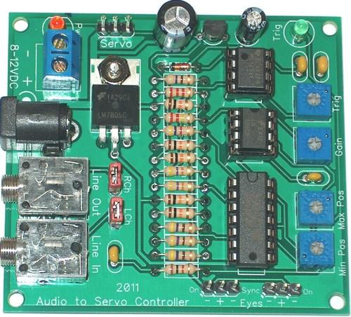
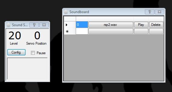
ww321q: The movement of the mouth with ARC and opening servo sound and playing with soundboard wav file, it is very easy just have to play around with controls microphone, the microphone near the speaker of the computer to try and listen at the same time . You can also connect audio output from the pc with a dual connector to the speaker jack and microphone input of the pc. There is a circuit to synchronize the sound with the movement of a servo and the flashing of the LEDs for the eyes:AUDIO servo CONTROLLER I thought about this option because the 20 digital ports seemed scarce for my project, I can handle this circuit servo-independent mouth ez-b, however the configuration I have now with ARC works beautifully.

User-inserted image

User-inserted image

Spain
#32  

MovieMaker: STYLE? clear man! Did you know that a recent study of sociology about what people appreciate about robots now says. that he likes the consumer is the appearance of the robot, and what you like least about the function performed by the robot. That's funny right?:)

Spain
#33  

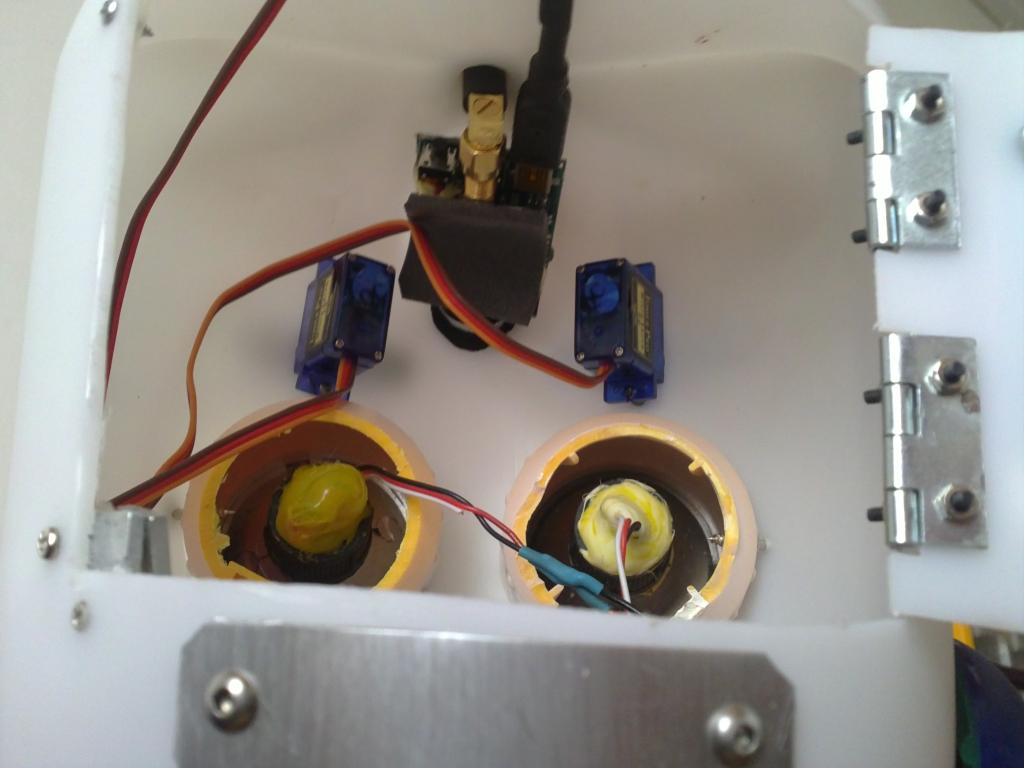
From the gate to access the servos, eyes, camera and support for pitch axis. The pitch axis is a tube of carbon fiber pieces 8mm 10mm aluminum tube and washers to center its position. This shaft is mounted on a shaft of a car rc. The stand has two bearings to rotate smoothly and the center of gravity of the head has been taken into account for the weight distribution. Being very close to the equilibrium point the servo has to make less effort. Despite my efforts to remove all buzz neck servo, some head positions produce slight buzz, which is not a problem implementing the option "auto relase." After one second the servo is muted.

User-inserted image

User-inserted image

#34  

yep! Looks are important! Thanks for the info. I will continue to follow this.

Mel

#35  

I sort of have an understanding of the face, eyes, brows, etc.

But, I would like to have more detailed pictures of the neck mechanism and the jaw mechanism. Perhaps some brief details on it. It looks like you have two or three servos in the neck. I see where the bottom one moves the chin up and down. I just don't understand how it is all hooked up and works.

Also, is the audio board required? Doesn't the EZBoard have a section on board to do this?

thanks,

Mel

#36  

ok, I looked at the drawing and I understand a little better. You are pivoting the head by the EARS. The bolt going through there is letting the head title up and down. Excellent! Now, WHERE did you find the bracket that attaches the head to the base? More details on those materials, please. I think you have an Excellent plan. I would place nonleakable Jet-ski batteries in the bottom. That's what I did with Leaf after a sealed battery burnt a hold in the floor in my office. Right through the carpet and the wood in a circle about 6" wide. With the Jetski, I can turn them upside down right side up and lay them on their sides and they will work and not leak.

Mel

Spain
#37  

MovieMaker: The support between the head and the base is half a size 450 helicopter chassis, I used this because I needed a trip up front-back and a vertical support from the neck not allowed me the desired travel because the jaw had hit straight support. This support has required modifications and additions of aluminum, if you are in a similar situation can manufacture all-aluminum support by two equal pieces and put them together with screws or threaded spacers.

User-inserted image

User-inserted image

Spain
#38  

By the way Mel does not need the audio board, ez-b incorporates the function: Sound servo simply look at the tutorial, this function gives a servo motion as a function of sound received by the microphone of the pc or pc audio input, greetings.

Sound Servo

#39  

R2, you are a Genie -ous! That was GREAT!!! And, so is D.J.!

Mel

Spain
#40  

Simply stunning! Russian robot ar-600 looks like a clone of the ASIMO robot is to be a source of inspiration for me in the design of the arms, you can see the axis of rotation and servos that move the fingers in great detail.

United Kingdom
#41  

WOW R2D2

Rsp robot is a masterpiece of homebuilt robot tech.

Got to say it again "WOW".

Steve_C.

#42  

@r2d2 hey man great work , I noticed the plan is going to have a strong base , if I could make a recommendationbi think every builder would agree on..... Buy a used jazzy power chair , they been around forever so there are replacement parts and I usually see them sell for 200 to 400 and your base and motors ectvwould be covered.
United Kingdom
#43  

I agree jstarne1 and the motors are silent too.

Spain
#44  

Glad you like the project, certainly the wheelchair motors are the best option and in addition are private funded to run silent a long time with a lot of weight, I realize it and is a great tip, however the design the robot is not closed, and anything that might change in the future to improve it are welcome.:)

Australia
#45  

Impressive - personally I love big robots but I think there is a trap of over complication. The more components, wires, cpu's etc the more vulnerable they become. Whilst this is a great effort - no a fantastic effort - I think there is plenty of room for reviewing the project and looking at ways to simplify every aspect of the robot. Simplification on a project this size is a massive challenge but who ever follows the path will be a world leader in producing the ultimate Robot.

Spain
#46  

Hazbot: Indeed the complication is greater when the robot is large in the case of a building from scratch. I like to consider the distribution of weight on each piece mobile when these pieces are very heavy. The servo extension cables I bought are: 5 cables 100cm 10 cables 80cm 5 cables 60cm 5 cables 50cm 5 cables 40cm 10 cables 30cm 10 cables 20cm 10 cables 10cm And I think I'll have to buy some more. I have not much time now to continue the project, it may take one or two years to complete but I think it will be worth the effort. The simplification of the project is one of my goals, it was initially designed the robot without mini itx integrated ez-b only taking advantage of all its outputs. Greetings.

Australia
#47  

It certainly will be worth the effort and yes, these Robot projects are massive time grabbers. I think once you get it to completion the simplification period will be a natural progression for you. All the best and I know all of us out there tinkering away on our machines will be keeping a keen eye on your progress for what will be an amazing Robot.

Cheers R2D2

Spain
#48  

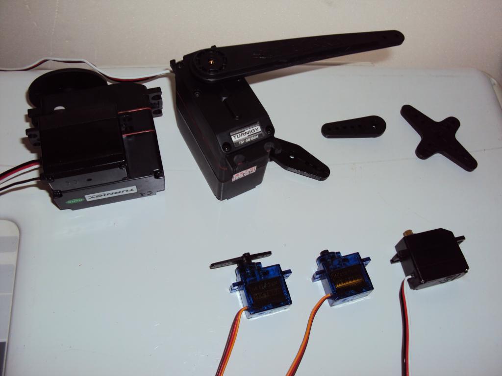
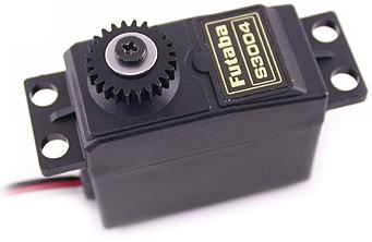
I have received some servos lost in space and time for more than 6 months after leaving Hong Kong were absorbed by a black hole that explains it. Two Turnigy S8166M servos to move the elbow joint (compare the size with standard servo Futaba S3003) and various mini and micro servos for the construction of the first hand and some pieces of useful and cheap to build rc helicopter arms. I am currently in the design, parts search and supporting evidence to build an arm and test the design if successful building the second arm.

User-inserted image

User-inserted image

#49  

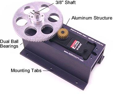
Hey buddy , I picked up robotzone gearboxes that can use standard size servos (or larger servos if you get the next size up) and they are made to withstand 200 pounds on the smallest model. They have various gear ratios , I picked 5 to one but they have higher. You could use these for shoulders , elbows and even your gripper. Servocity.com. I bought the hsr5995 servo for mine which is 414 oz torque and I'm putting it in the 5 to 1 ratio gear for over 2000 oz torque from a standard size servo:) , the servo was 59.99 and gearbox 59.99 , great deal.

User-inserted image

Spain
#50  

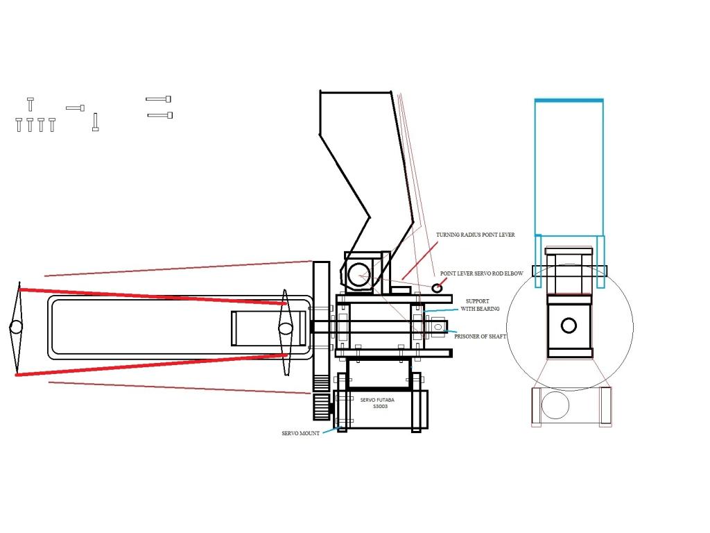
Looks like you've seen my designs on the webcam! Shoulder effectively use a similar one I thought of servocity Also with a 5:1 ratio and plastic gear, I think the best option for the point of the effort arm, the Turnigy servo is mounted above the axis of the shoulder to act as a counterweight, and the transmission works with a rod steel on the hinge of the elbow. www.servocity.com/html/spg805a-bm_standard_rotation.html

User-inserted image

Spain
#51  

New update, I'm working on the design of the arm, concretamenete at the elbow wrist and hand. First I decided the degrees of rotation of each moving part for what I do. The shoulder has 180 degrees of rotation. The elbow is 110 of rotation. The doll has 135 degrees of rotation The rotation of the wrist is 300 of rotation.

User-inserted image

Spain
#52  

In the picture above add the servo that attacks the large gear is not a continuous rotation servo, but the potentiometer or adjustable resistor is mounted outside the servo coupled to the long axis of rotation, with a belt and reducing pulleys to match the 300 of rotation that I intend. Removed the mechanical stop and adjusting servo got multiply adjustable resistance force servo and reduce its speed but with control over their positions. I have found that some servos can not take the 99 positions ARC, only approximately 70 positions, it is logical for the PWM limits. So if 70 positions and 300 of rotation calculated by 4.28 position.

Spain
#54  

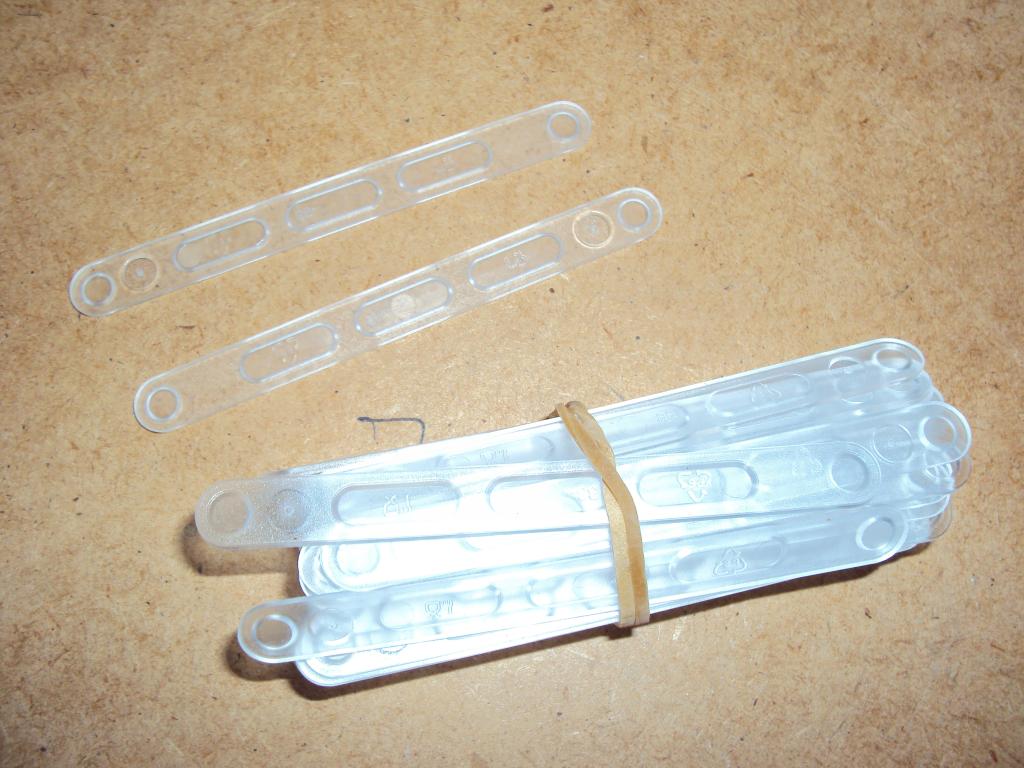
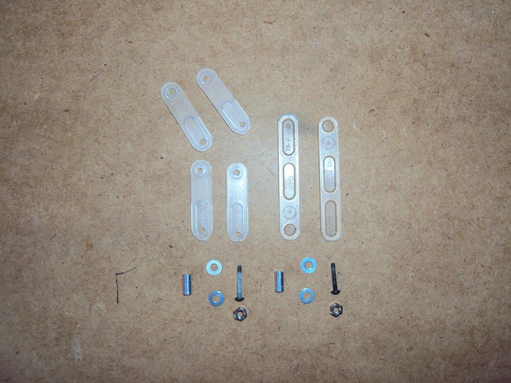
Thanks Bret, I'm also starting the construction of a hand from "plastic coffee spoons," the idea is a rubber band over the toe and a thin nylon rope below the finger to close the finger to pull the servo . Spacers and screws and bolts holes function as hinges for each knuckle, silver spray paint does the rest.

User-inserted image

User-inserted image

User-inserted image

Spain
#56  

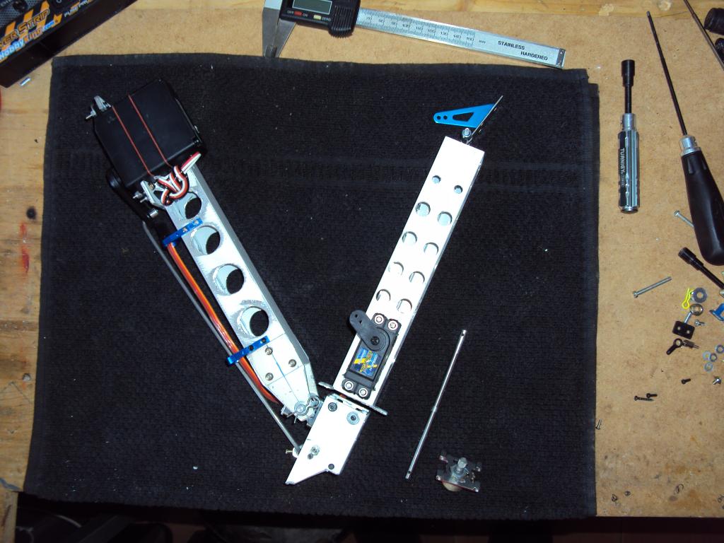
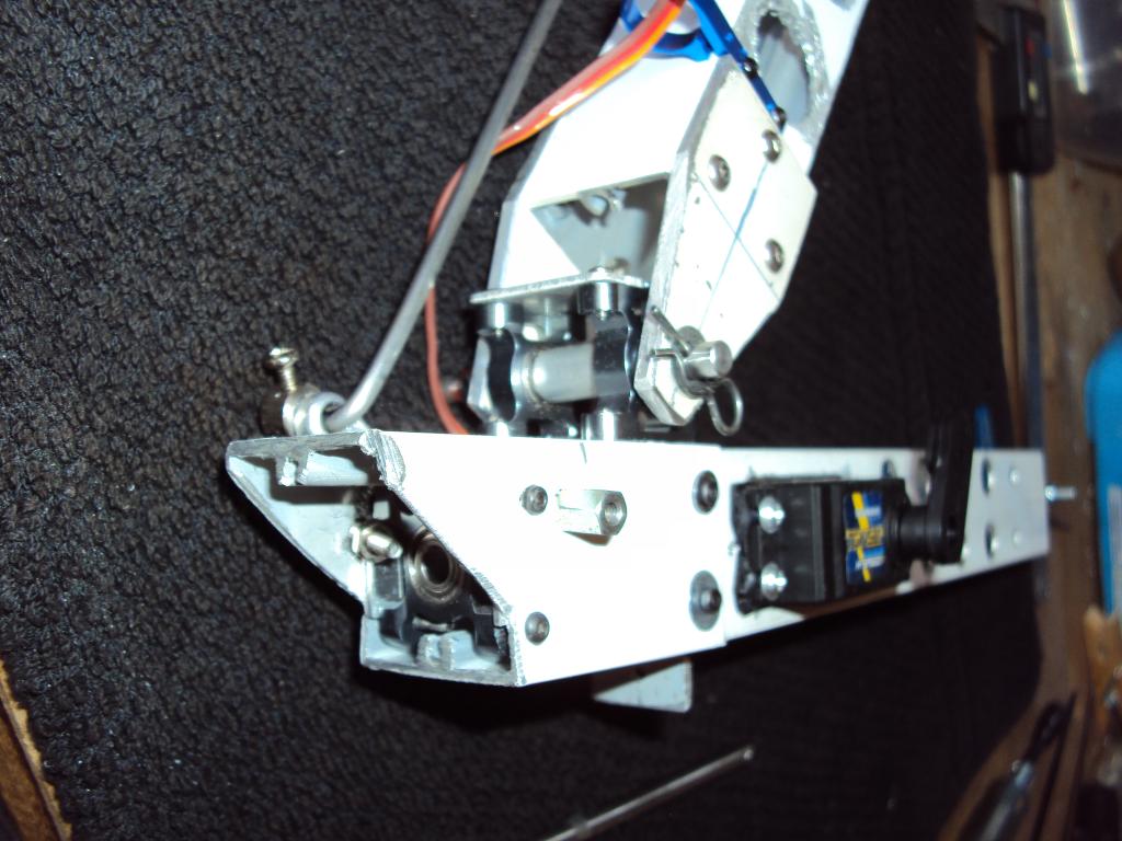
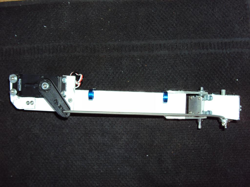
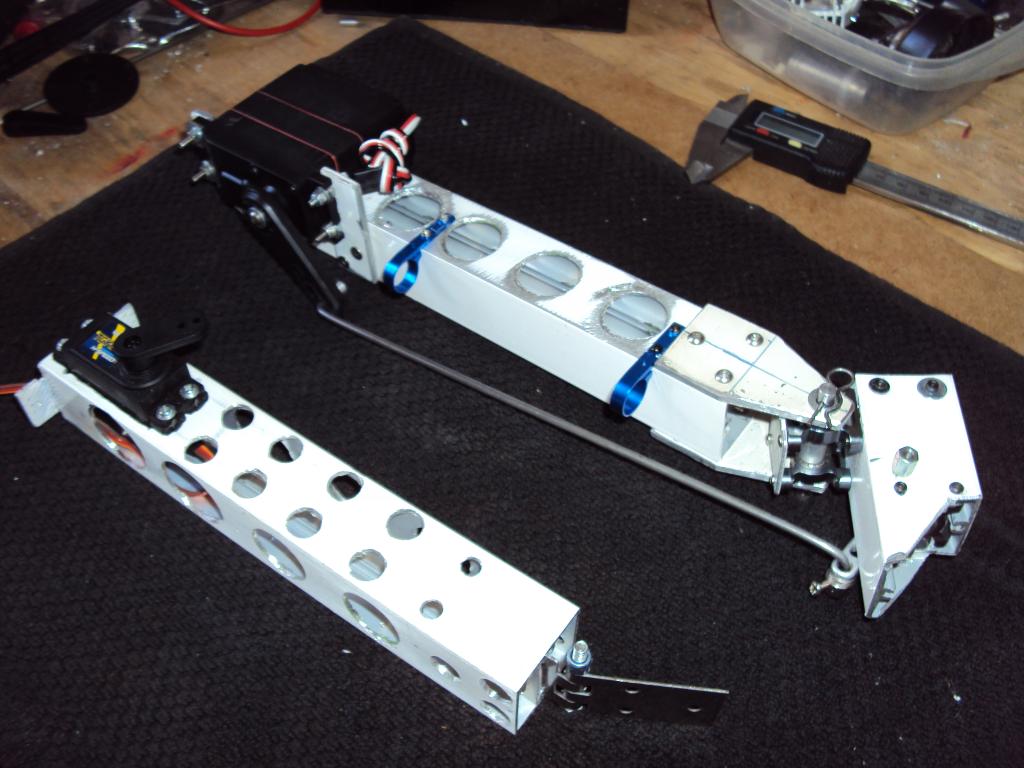
Progress in building an RSP arm with perforated aluminum square tube to relieve some weight, stands with main shaft bearings 450 RC helicopter, steel shafts, and molded aluminum foil and steel fasteners most. Hard work for building solid reliable but hopefully a long time.

User-inserted image

User-inserted image

User-inserted image

User-inserted image

Belgium
#57  

Amazing ! Good job ! Congratulations !

Spain
#59  

Thank you all, more data tomorrow.;)

Spain
#60  

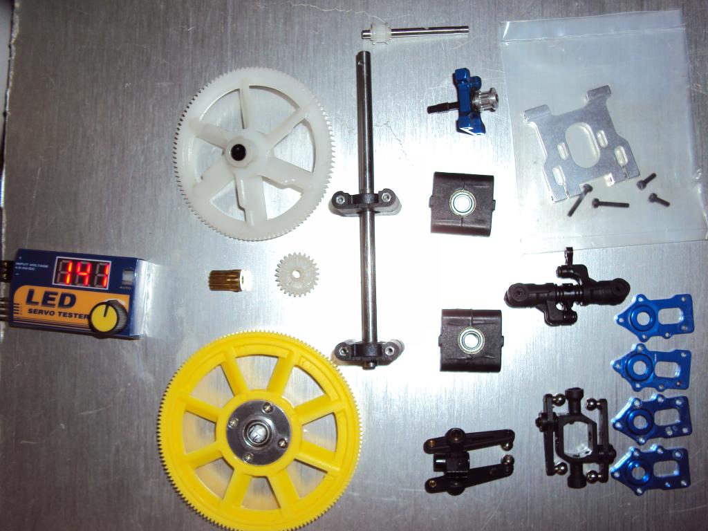
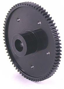
The next step is buying SERVOCITY a large gear of 100 teeth that attaches to a steel shaft and is in support of the elbow, then a small gear which is mounted directly on the servo spline shaft (no servo futaba or hitec, and can be metal or plastic) with this you get a great reducer of speed and force multiplier, I use the Futaba S3003 servos supplied by the kit. Ofcourse you have to make the servo potentiometer and install it on the steel shaft of the large gear. These two gears are cheap and make a servo S3003 in slow, but with approximately 20kg of force.

User-inserted image

User-inserted image

User-inserted image

Belgium
#61  

Waw, R2D2, your robot is really fascinating ! Great job !

Spain
#62  

Thanks PhG! Now I'm working on the drive system, a faulty gear reducer forces me to buy a replacement and gearboxes with shoulder servos are expensive and I hope santa will remember me. Also in the arm and in the power system. For the system of energy I have received this nice fuse box and connect the voltage regulators for different needs.

User-inserted image

User-inserted image

Spain
#63  

And hands have abandoned the idea of coffee spoons and I will buy these hands and modify them with servos. PhG greetings!:)

User-inserted image

#64  

R2D2

What voltage regulators are you using for the different voltages? Are they purchased boards or are you building them yourself? I have been looking at the 3amp switching regulator adjustable modules from Dimension Engineering. But they are $25 each.

#66  

Are you the one who is selling them on EBAY? I do have some of the LM317 regulators and heat sinks at home already. I think I will build the circuits like you did and try that. Do you think I will need a cooling fan?

Thanks

#67  

Yes, put a cooling fan on your electronics because.they.get.hot

Spain
#68  

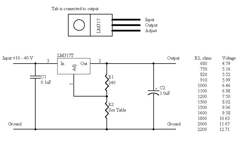
In my case I did not need a fan, the cooler is great and works well, but if you put fan no problem. I am not the eBay seller, I have only seen these regulators as cheap as buying the components and the board and make them yourself. This is the scheme, simply replace r2 by a potentiometer resistance of 2200 ohms.

User-inserted image

Belgium
#69  

Hi R2D2,

I'm eagerly looking for your robotic hand servo modification. If possible, make some videos. I'll continue with my robot within a few weeks when I'm back from my holiday. A robotarm/hand extension is one of my extensions.

Greetz,

PhG

#70  

Thanks R2D2. I tried the circuit and it works great. I will build four circuits; 9V, 6V, 5V, and 3.3v. Next I will have to figure out how to lay this all out neatly and add terminal blocks.

Spain
#71  

PHG: I guess I'll have more in a hand at home, but if I have very clear what I will do with it. -First cut the excess plastic behind the toes and build a palm-size. -Cut the union also thumb finger and tilt inward to grasp objects with the original design is quite poor, I'm thinking of making a tilt adjustable system that can fix your position with a screw, so I can taste the position more effective. -Then in hand mount two servos that I have and connect to the fingers (all the fingers except the index finger are connected to a mini 3kg sevo) and separate your index finger of 1.8 kg micro servo. (with this combination of two servos can grab objects, pointing and waving)

  • And finally thin cords replace that bring some more elastic fingers, each finger so that its buffer will separate as an individual clutch can adapt to the irregular formai gripping objects (such as a drink)
Spain
#72  

Someone already put this hand servos but my modification is much more elegant ...:D

Australia
#73  

WOW..:) Who knows where this will lead... These larger robot projects are fantastic..

Belgium
#74  

Great R2D2 ! Do you control your robot and/or hand with the ARC or other software ?

Spain
#75  

I think you've confused that video is not mine, I found it on youtube, I meant that the modification of the hand that I will be more compact than the video, that is a simulation of hand size with two servos inside, taking advantage of fingers toy. In any case I will use ez-b with ARC software for the entire project. And incidentally demonstrate the possibilities of ez-b in a big robot. Ah rgordon; luck with voltage regulators, I got on the circuit board fiberglass with homemade acid formula and black permanent marker for tracks, quite easy and effective.

User-inserted image

#76  

If you are into making your own circuit boards here is a great find. You don't even have to use an etching tank! You print out your circuit design on a laser printer using a special paper they have developed. Then using a Toner Image Applicator, which is a heated roll laminator, the image is transferred to the copper board. Take the time to read through this info carefully. I got one recently and will be testing it out soon. I also got a miniature drill press that uses a dremel tool and ordered some micro drill bits to drill the component holes. PC Board Fab in a Box

No etching tank needed

Spain
#77  

That's a good system for professional circuits, integrated circuit or circuits that are close together connections from each other. Actually my system is very simple: 1 - components are marked on the plate with a pencil and then with a minibroca taldro with 1 or 1.5 mm. 2 - tracks are drawn with a black permanent marker better. 3-plate is inserted into a tray of homemade acid (hydrochloric acid 2partes to 20% purity, which is in stores cleaning, also known as "heavy water" and one part hydrogen peroxide to clean wounds ) eg 2 glasses of acid, and a glass of hydrogen peroxide) 4 - after a time the acid has been removed from the copper plate ( except the one under permanent marker lines) Then clean the pen with alcohol (from wounds too) and you are ready.

#78  

Radio Shack still sells the circuit board making kits you speak of... I think. The thing I like about this new system is if you find a circuit board layout in a magazine or on a web site you can print it out and transfer it right on to your copper board and etch it just by wiping the etching solution on the board with a sponge. All taking only a few minutes. I will test it soon and let you know how it turns out.

#79  

Yep, you could basically narrow a.design from a picture. So are you planning on the hands to be for entertainment and not really hold anything

Spain
#80  

Mainly for entertainment, but that does not mean you can not grab anything, depends on the weight of the object, its shape, the position of the wrist, the rubber grip of your fingers will ride in the grip area and also of sevos the strength. When you take it out, have no doubt that I will make some nice videos of their hands manipulating objects, but nothing concrete block or gym weights.:)

Spain
#81  

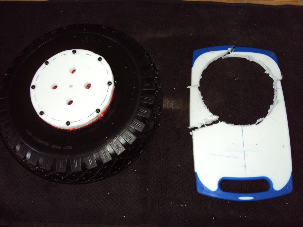
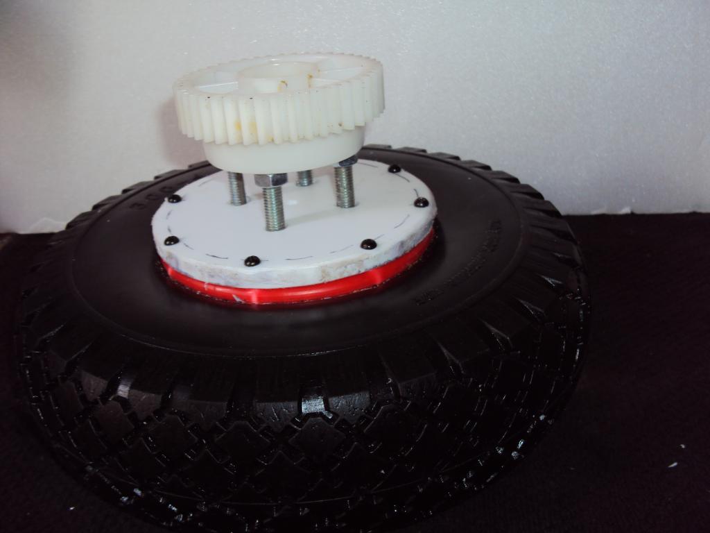
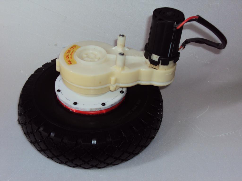
For the drive system with two motors utlizo dareway lowering vehicle, but the original wheels were discarded plastic, rubber and also those not clickable, are much better, with a diameter of 25 cm (9.8 inches) for use also in outdoor or urban areas.

User-inserted image

User-inserted image

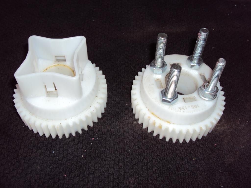
The system original coupling between the wheel and the gearbox, had the shape of a star, this is cut and mounted on four large screws last gear. I also use a hard plastic table (cutting in the kitchen) and manufactured a screw cutro adptacion between the gearbox and the wheel.

User-inserted image

User-inserted image

User-inserted image

User-inserted image

Spain
#82  

To prevent damage to the robot weight of the reducing gears, is used which traverses steel shaft and two wheels attached to cahsis aluminum, which avoids any torsion.. This easy axis is removed with a locking nut at each end. Besides the need to mount the L-shaped brackets between the gears and the chassis.

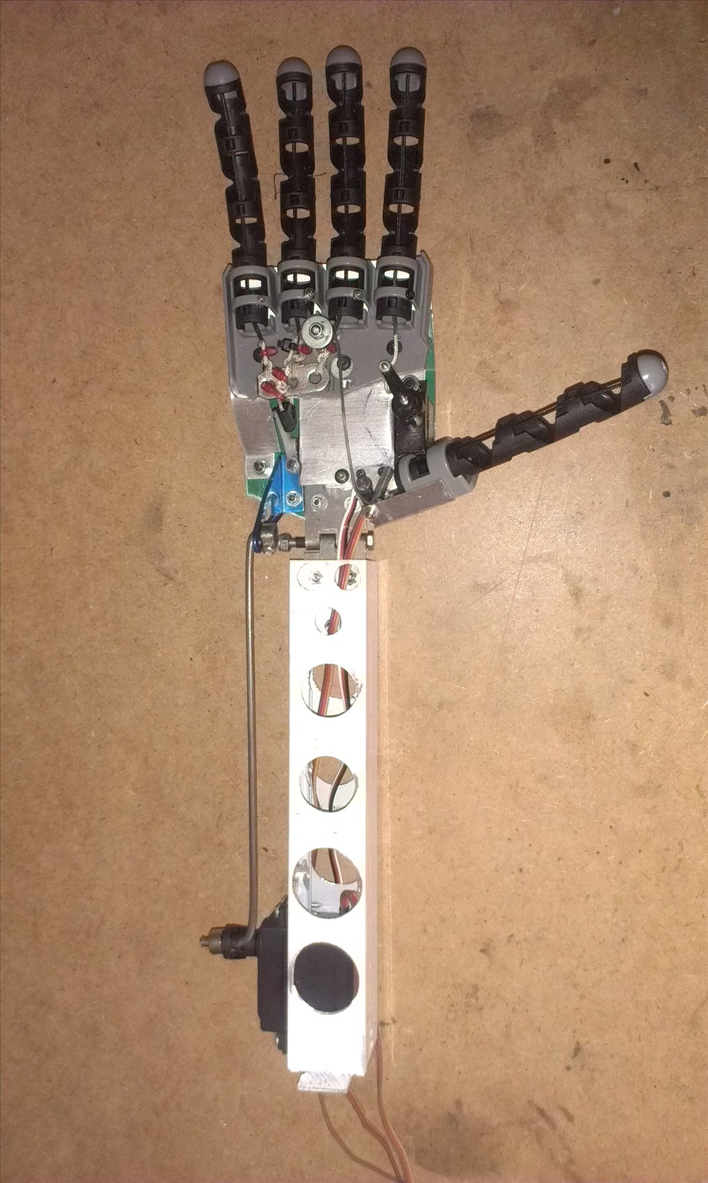
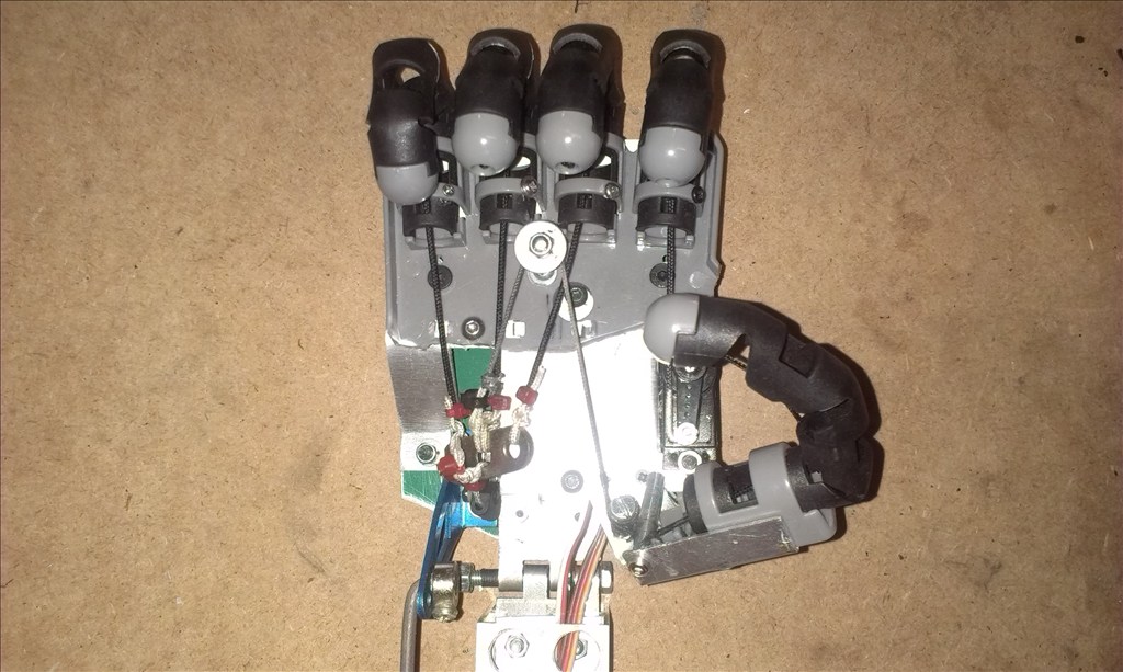
User-inserted image

Spain
#83  

Small Project Update: The hand has been modified, two small servos move the fingers in a combination that lets you index finger pointing, waving or take very light weights. Thin aluminum board, small screws and rope did the rest. While working slowly and almost time for the robot, watch your projects and breakthroughs ez-b and marvel, and good luck to all the Dj revolution waiting!:)

User-inserted image

User-inserted image

#84  

Awesome project R2D2! I love the creative "hacks" on this forum...and well engineered/crafted hand too I might add

#85  

That hand is awesome! As well as your drive system! Nice manufacturing.

Spain
#87  

Thank you all! Here are some videos of the hand, need a good injection in my wallet to end the arms, but donations accepted, haha??.:D

United Kingdom
#88  

I'm loving the hand, I plan to do similar on my big build when I eventually get to it. how strong is the grip on it?

Spain
#89  

@ RichMR2: the hand strength to grasp objects is small, you can grab box of cigarettes or objects of similar size and weight. Although the servos have strength, fingers are of a plastic-like material rubber and these are twisted slightly, is rather to gesture that manipulation, greetings.

#90  

Now that's cool. Thanks R2D2 for the vid. Amazing stuff and very helpful. I'll be needing some of these ideas when I build the arms and claws on my B9. However it will be much less elaborate then your creation. All I'll need to do is open and close the claws and maybe even rotate them around. It's good to see how someone like you has done this.

Thanks again! Dave