


cE9s4PsOgeBQIORwjd5!~~60_1-634818020230156250.jpg)


BO)Lupuc4g~~60_35-634706297915000000.jpg)
LupbT6!~~60_35-634706298769375000.jpg)


C5j!~~60_35-634655044863125000.jpg)


C5j!~~60_35-634659603510781250.jpg)


C5j!~~60_35-634651704046230469.jpg)
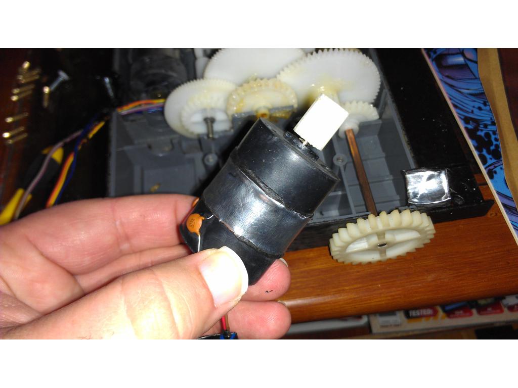


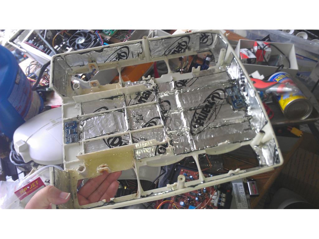

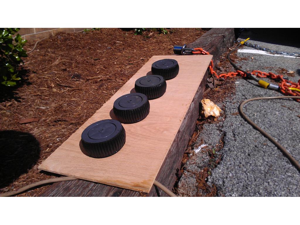

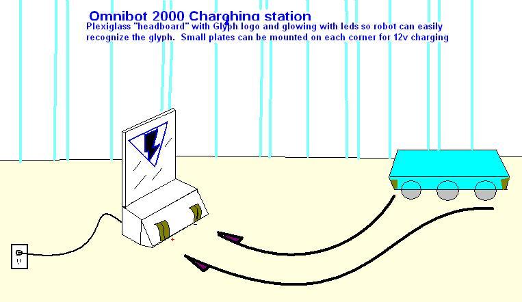
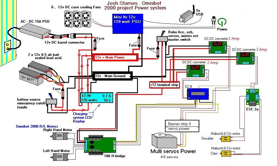


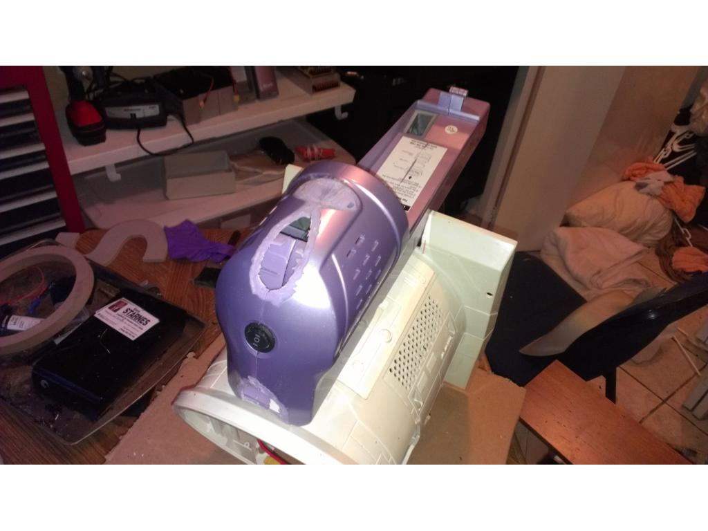


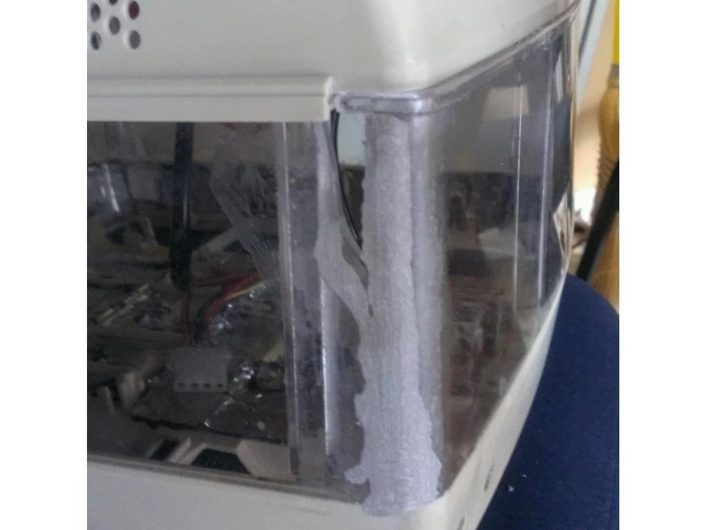
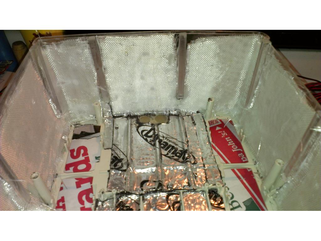


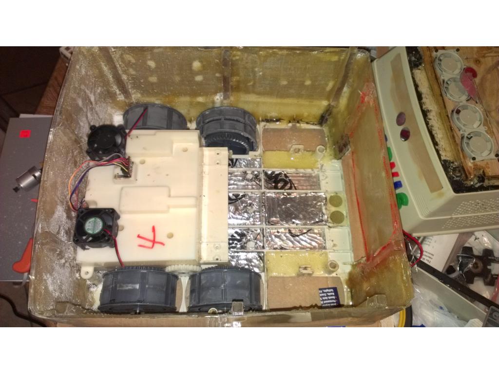
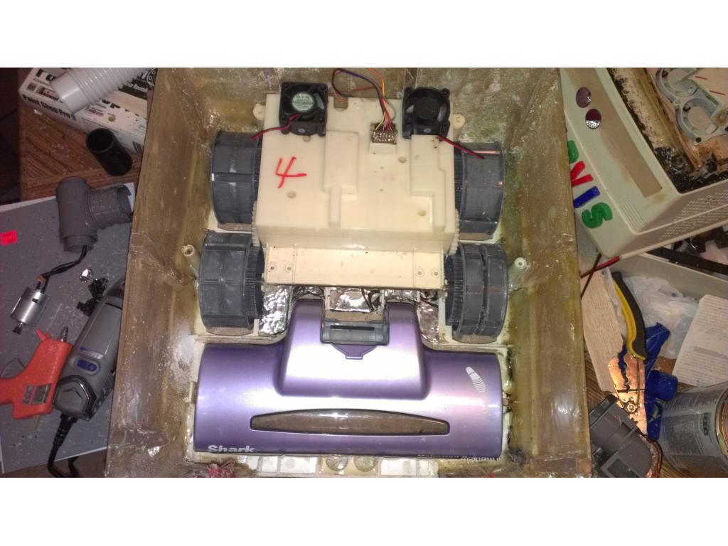
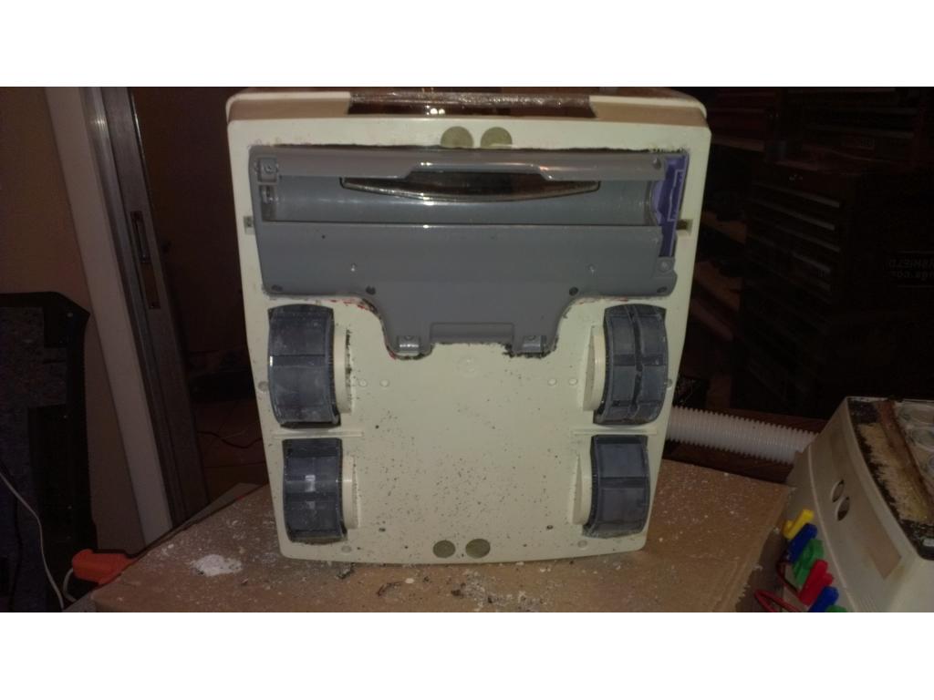
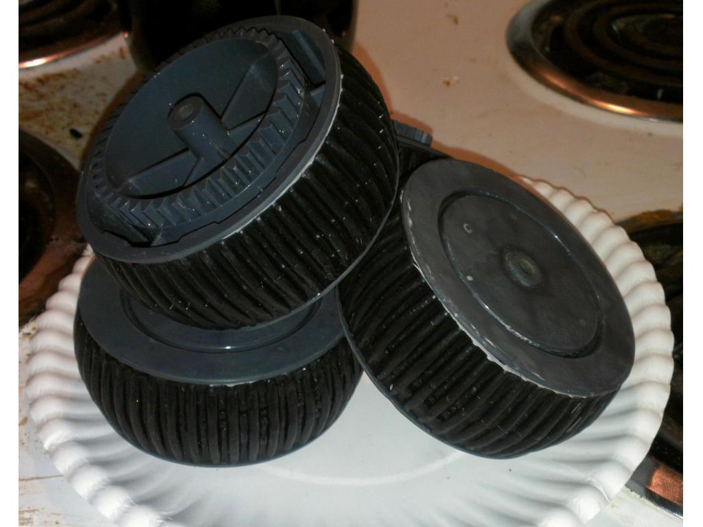

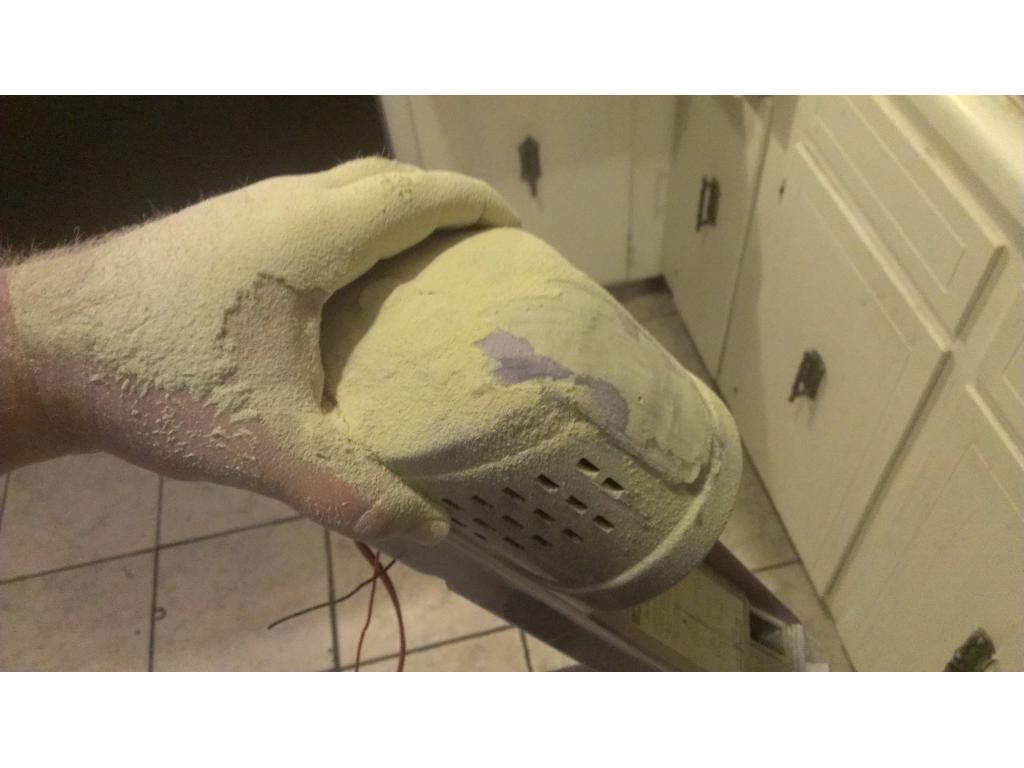

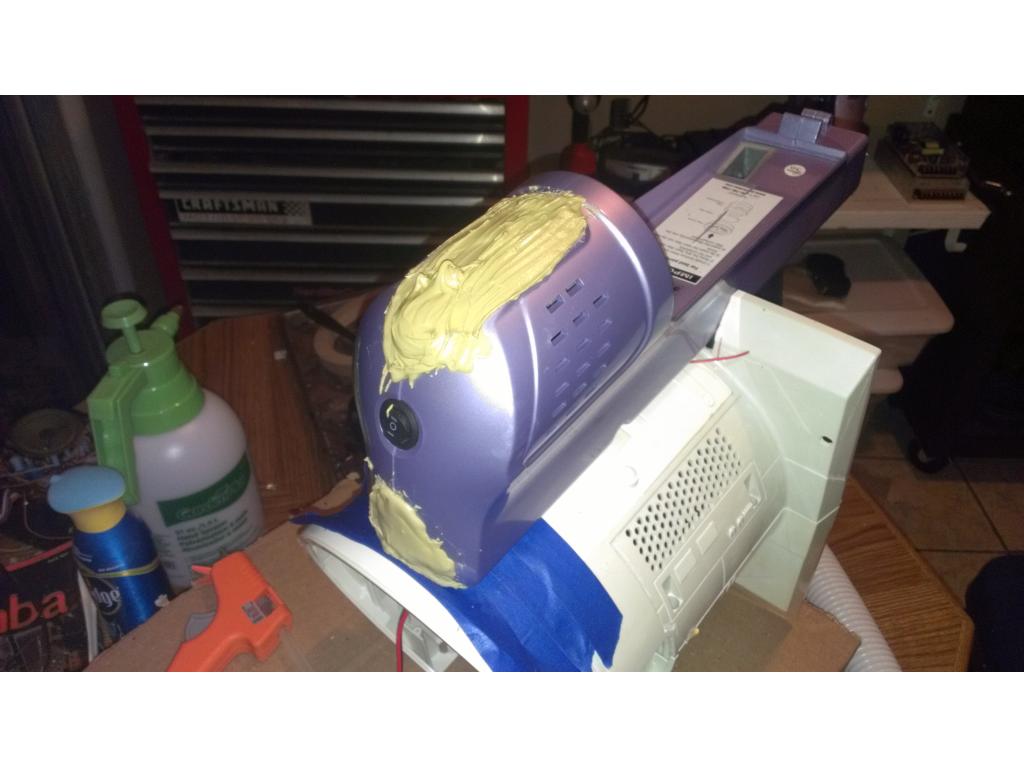

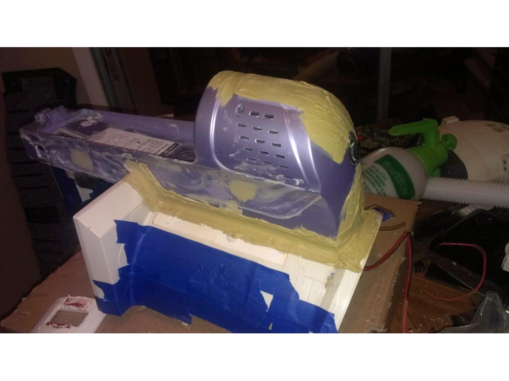
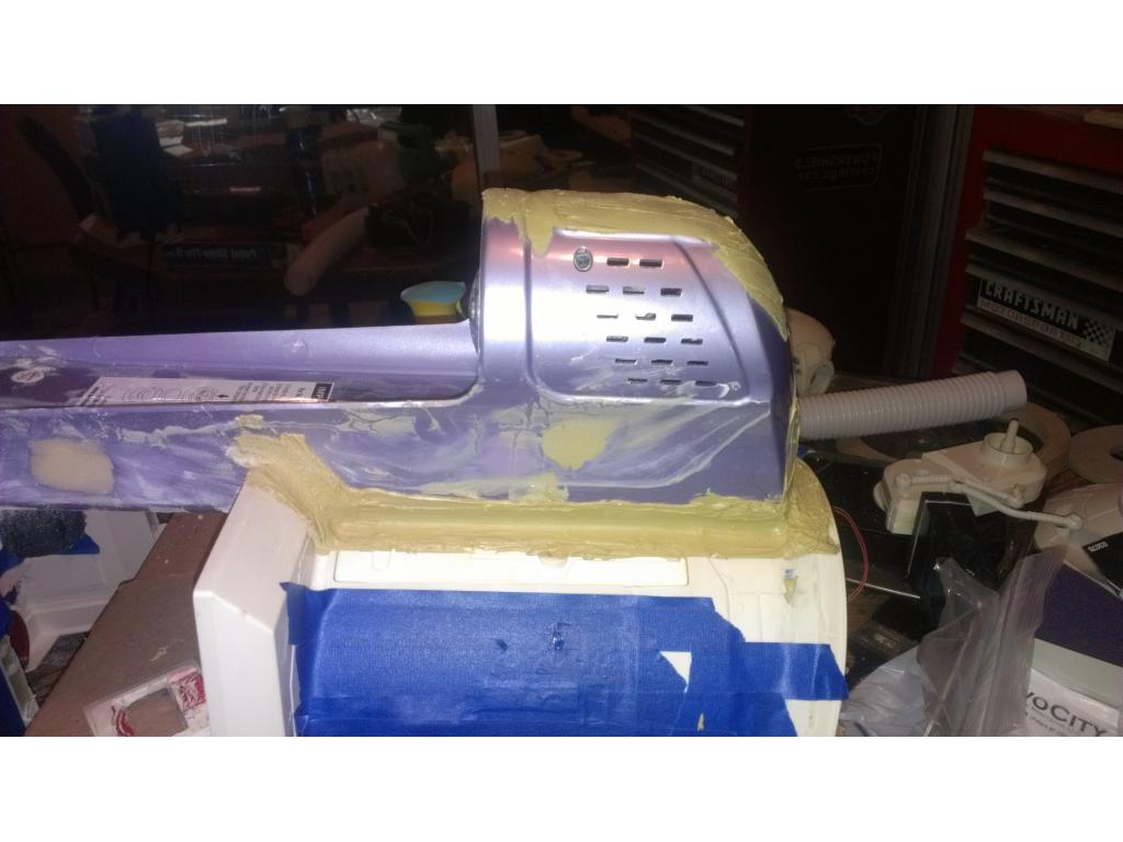
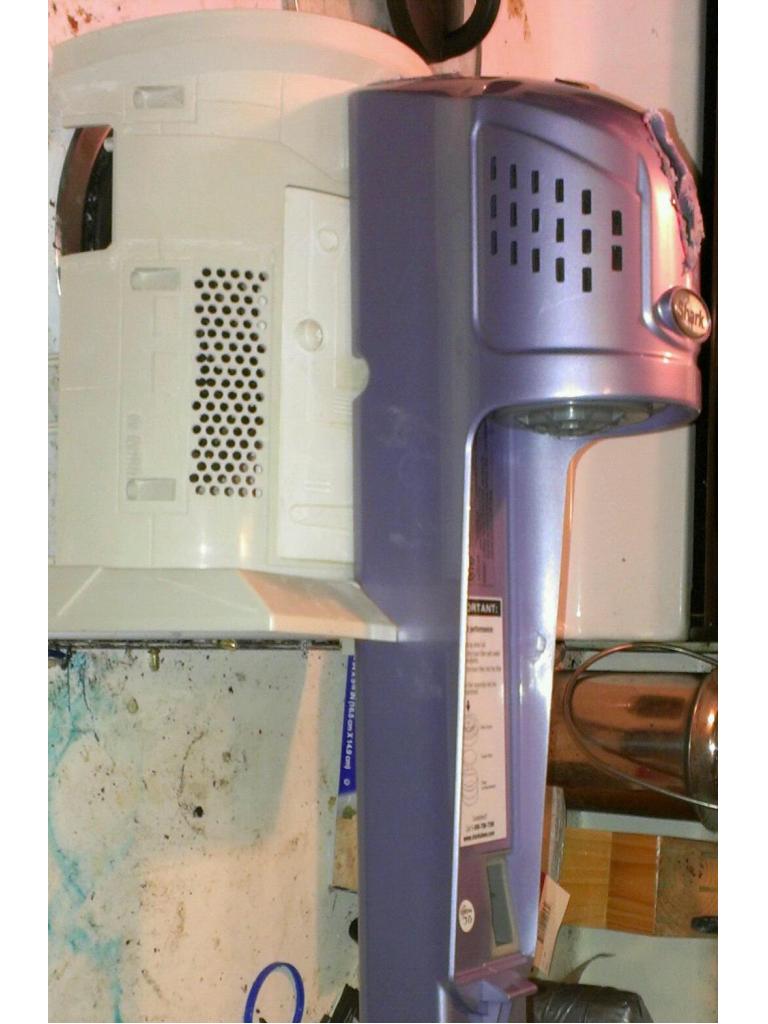


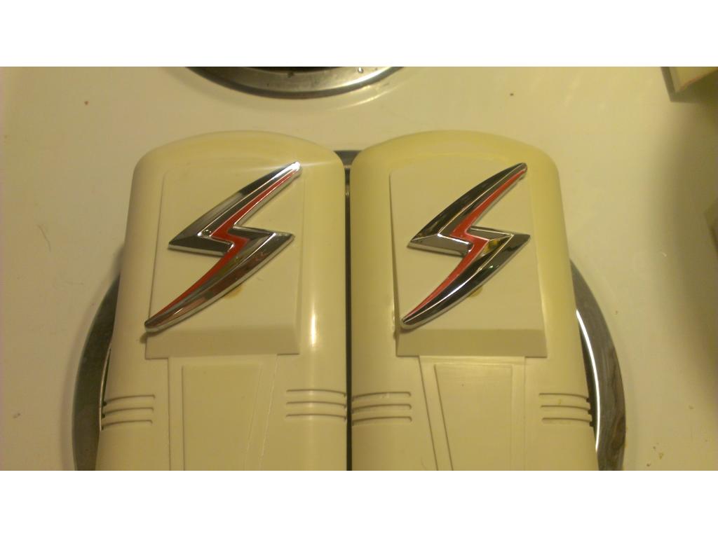
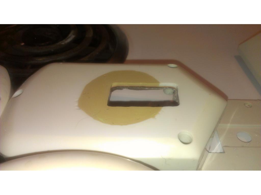
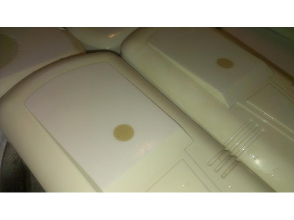
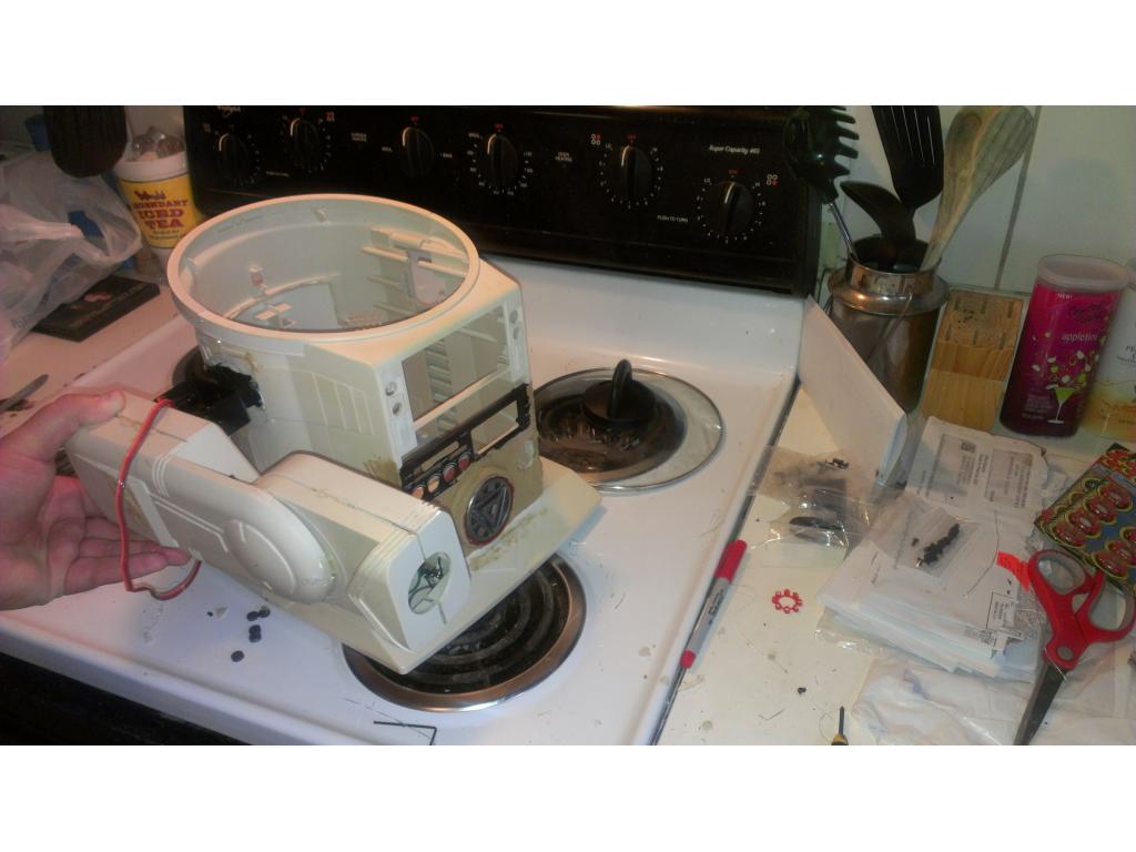
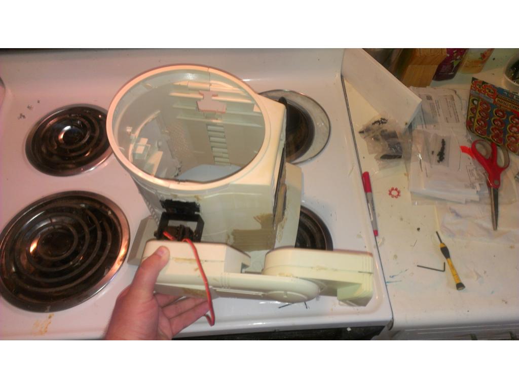


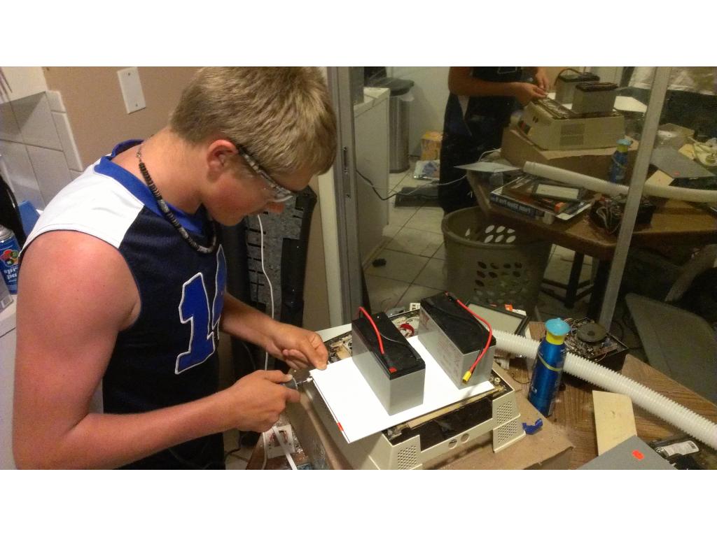
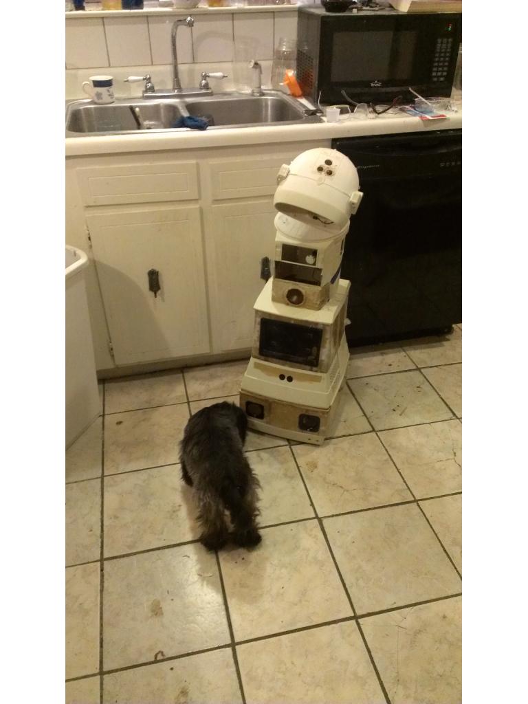
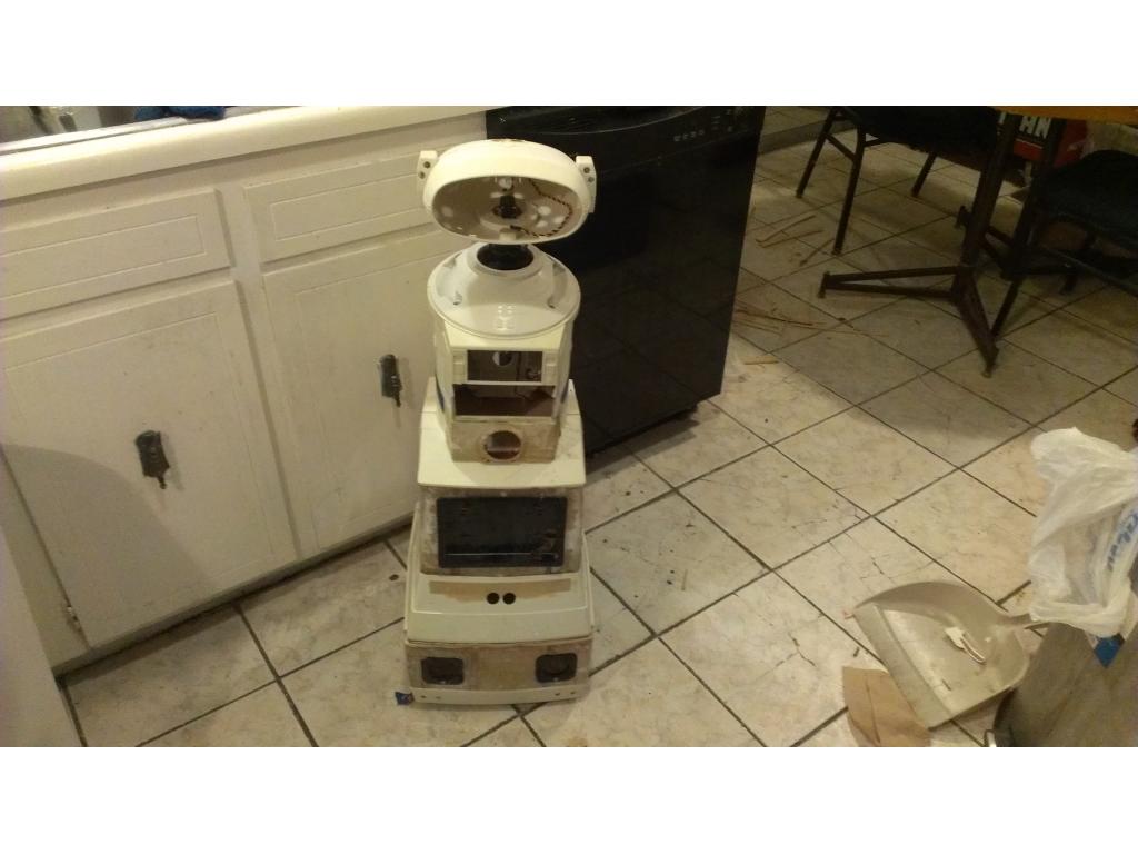

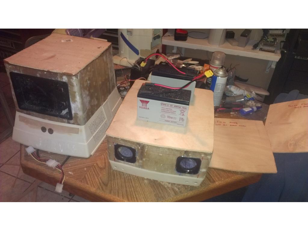
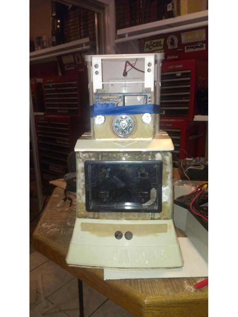

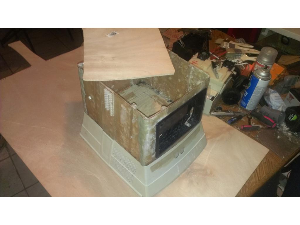
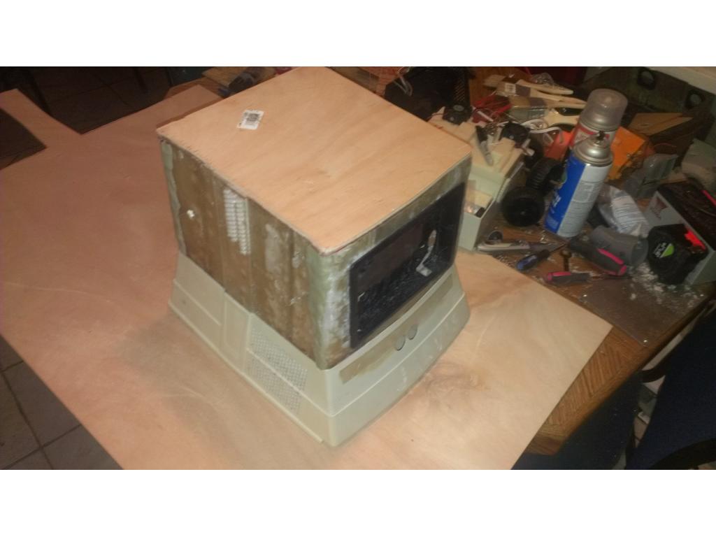
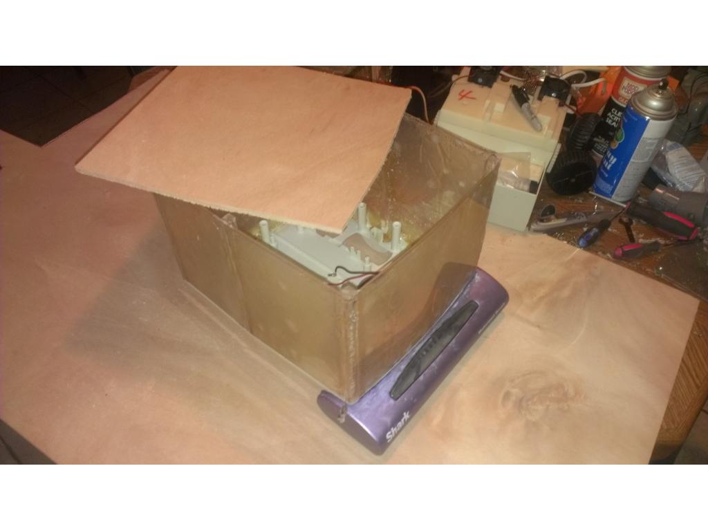
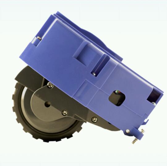
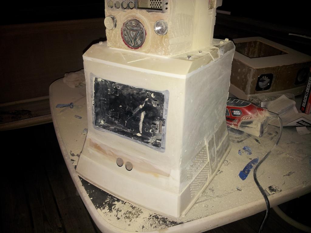
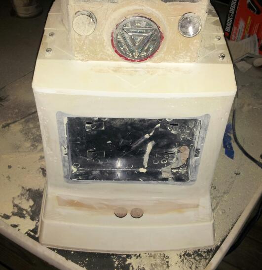
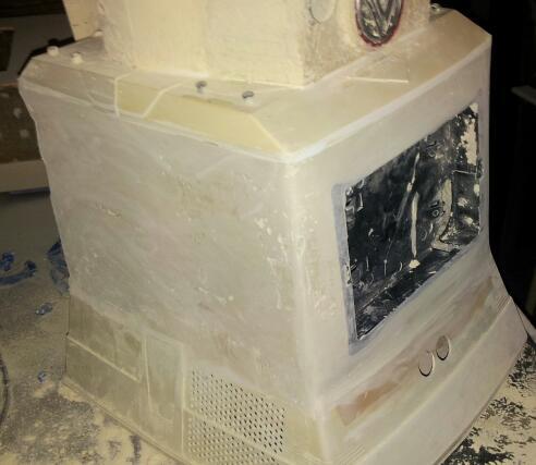
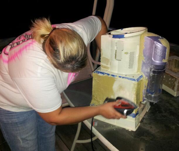

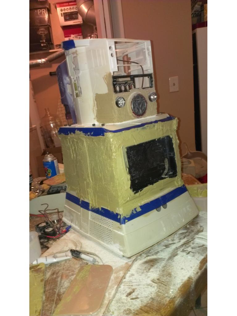
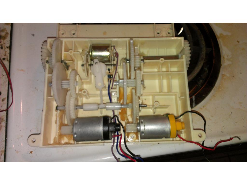
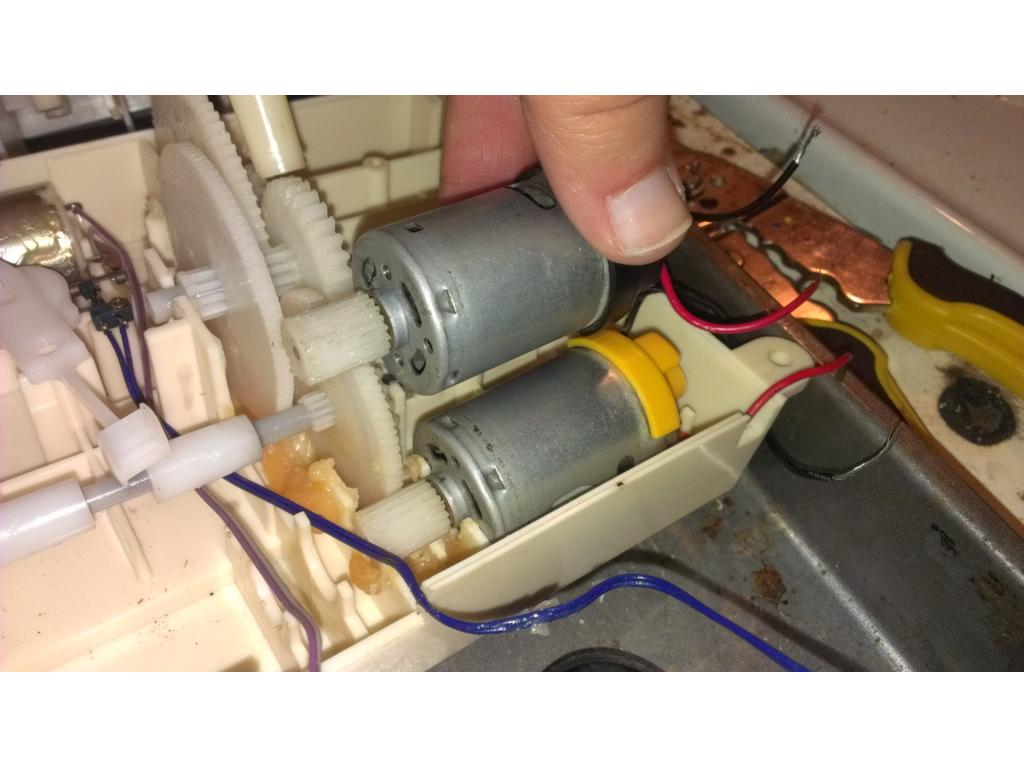


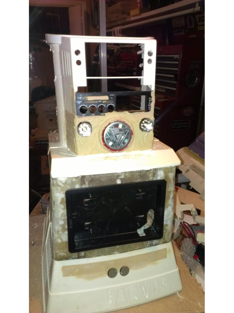

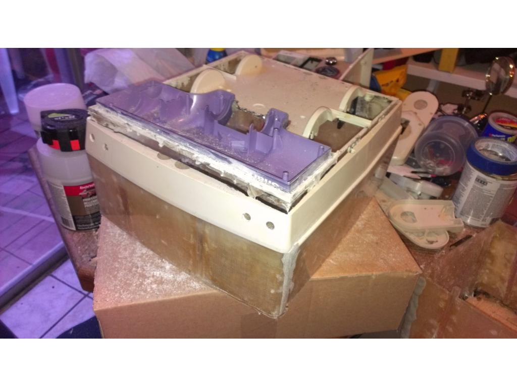
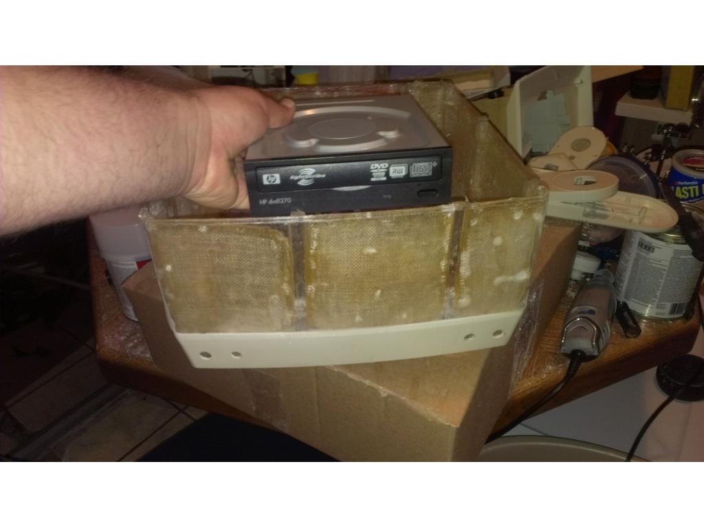
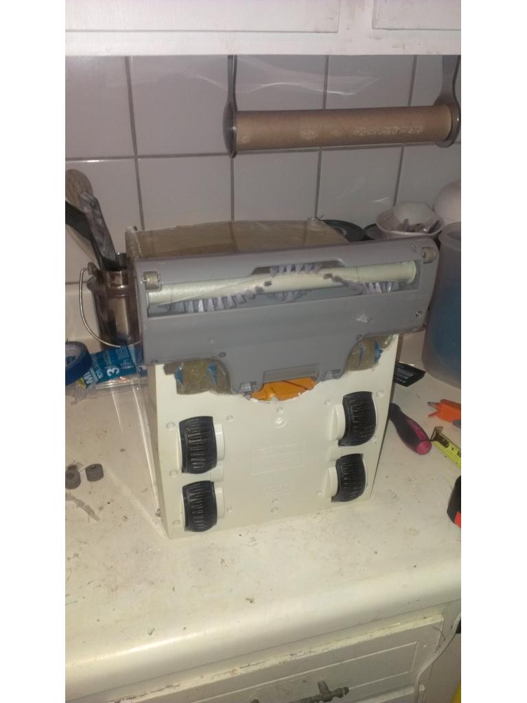
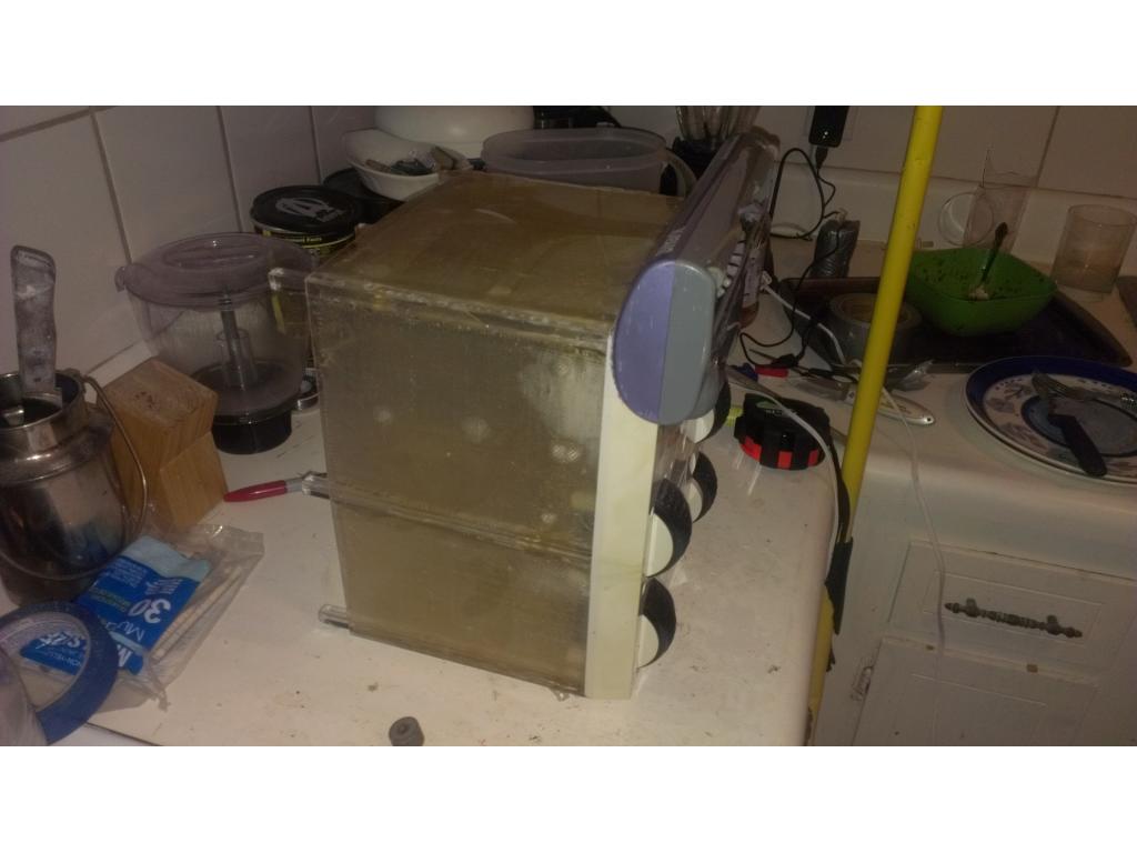
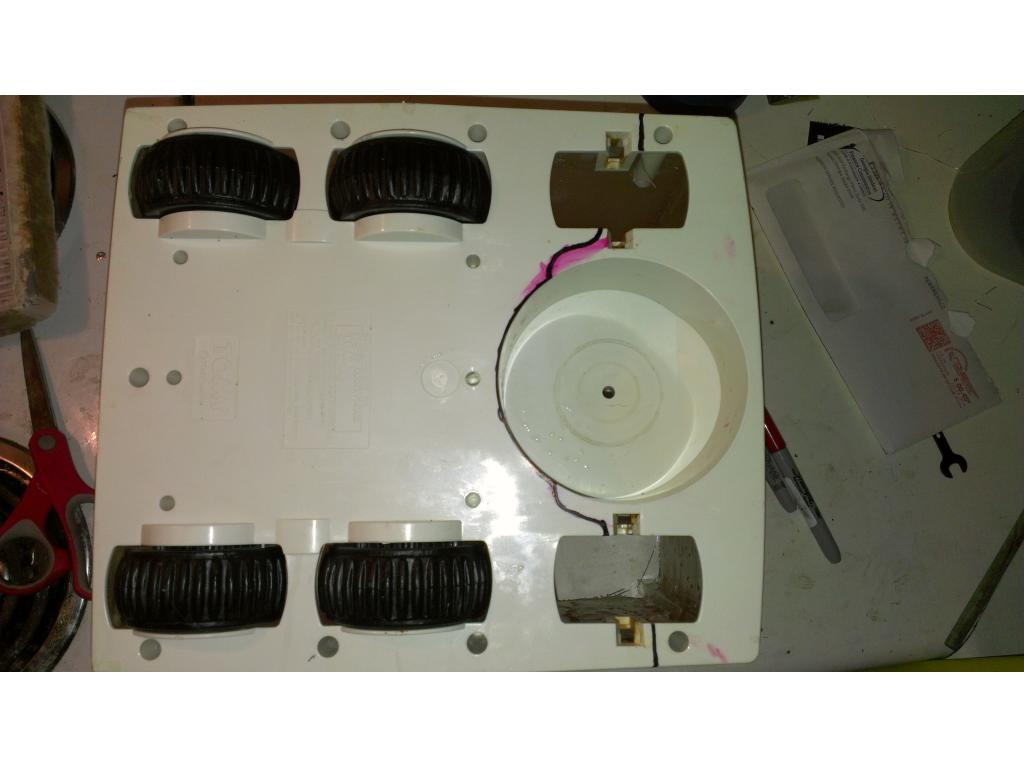
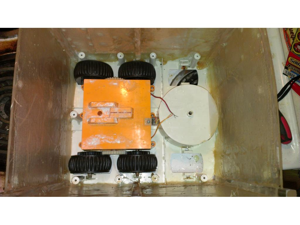

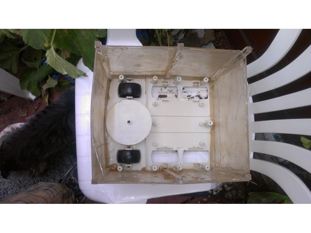
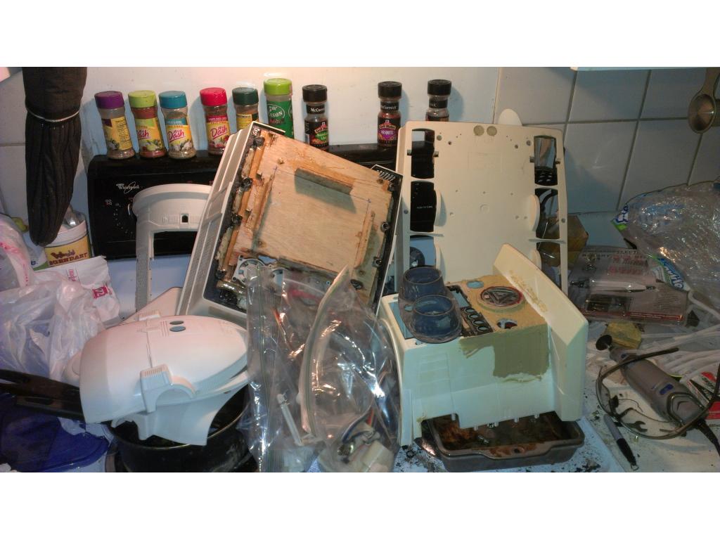


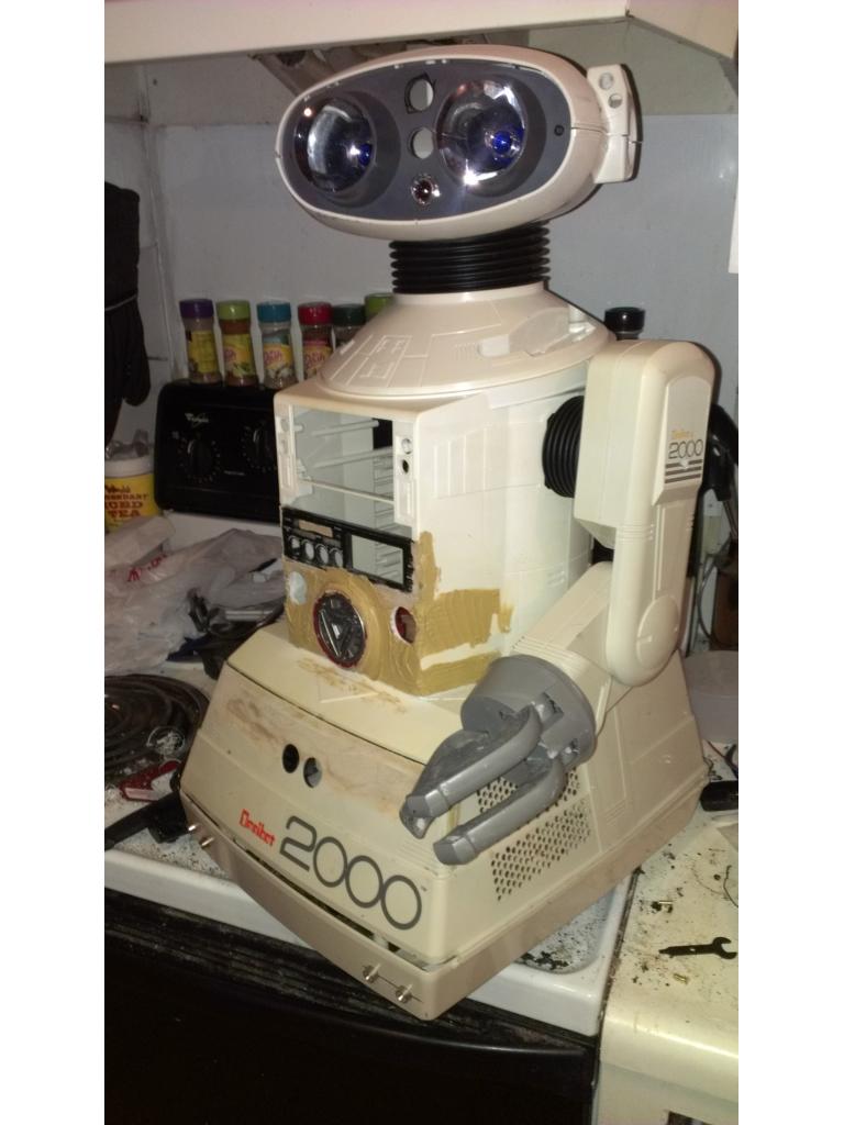
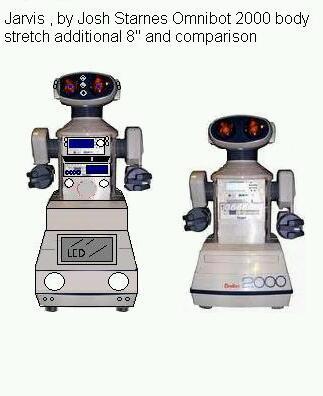


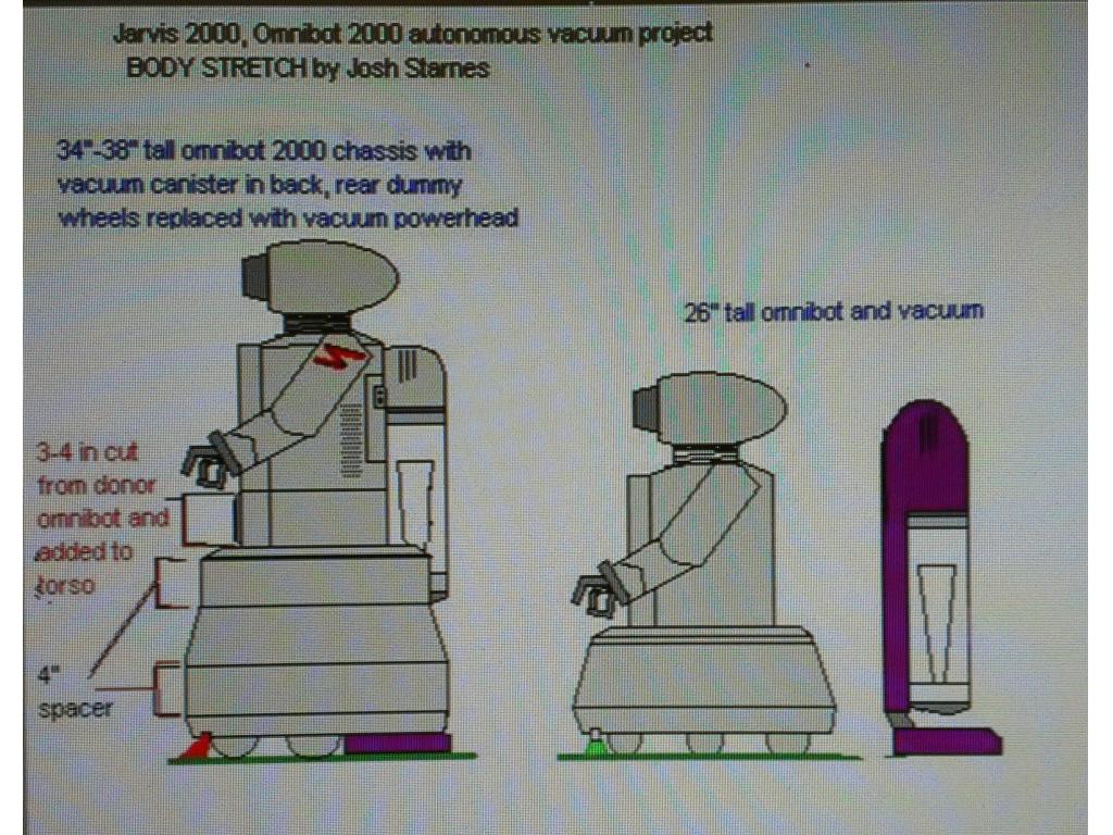


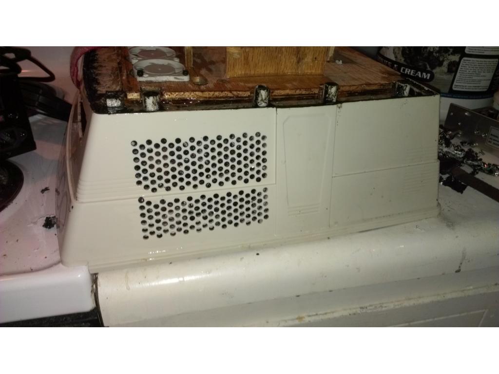
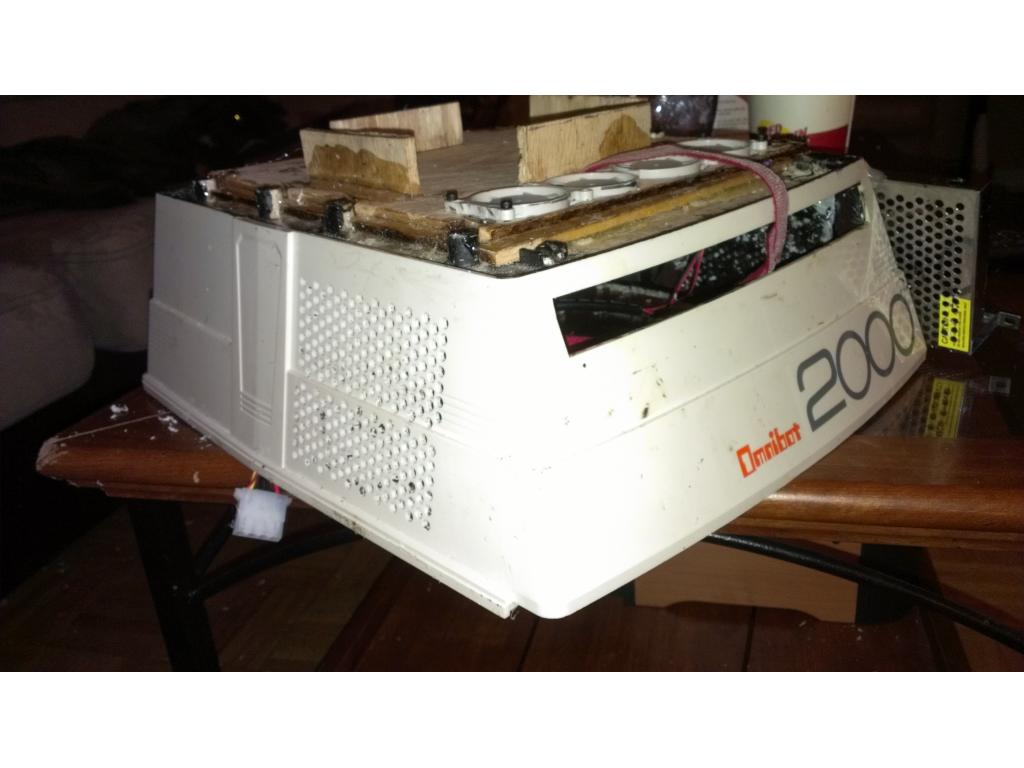
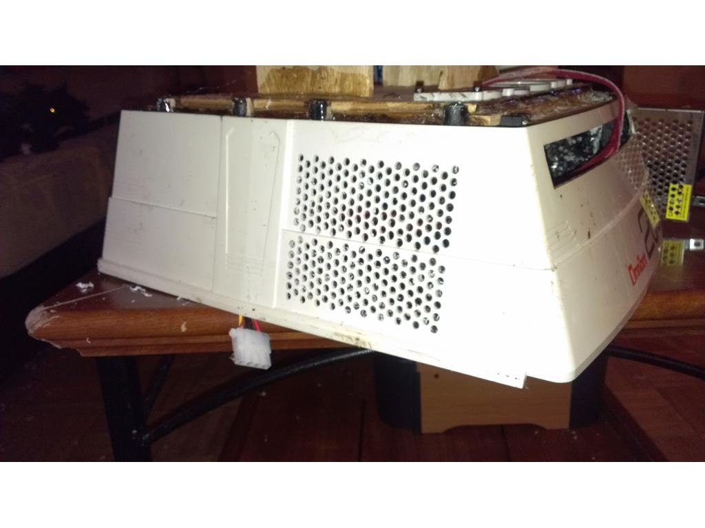
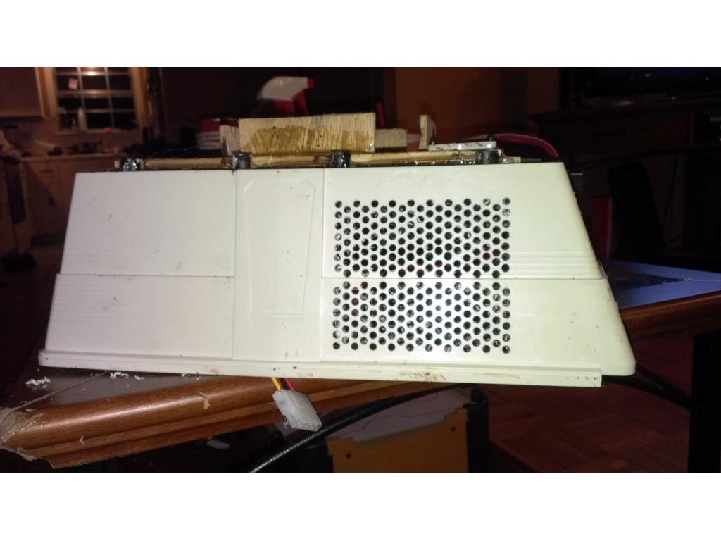
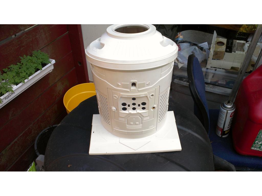
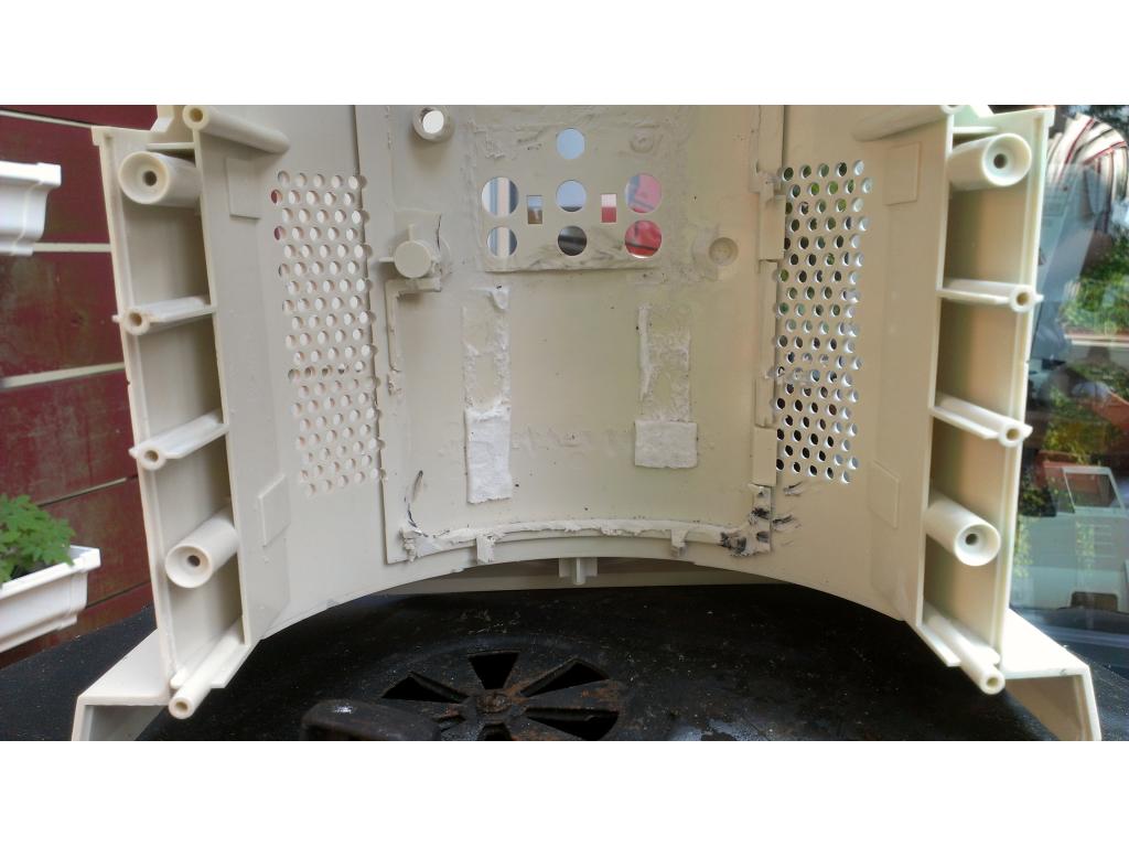

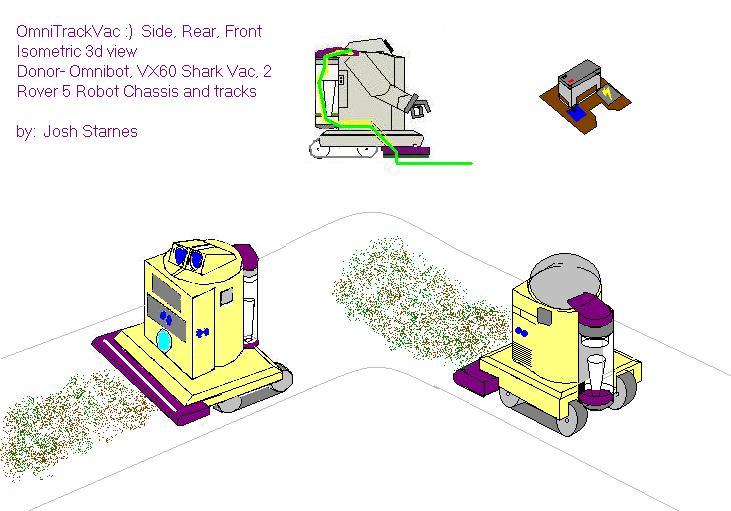
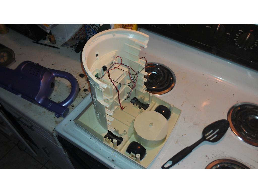
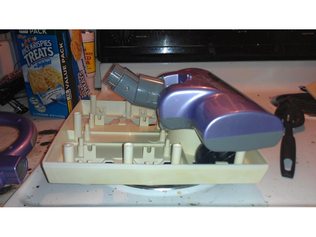

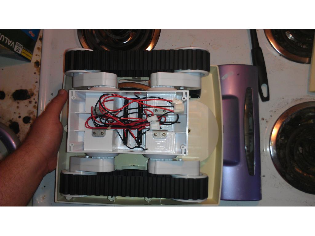
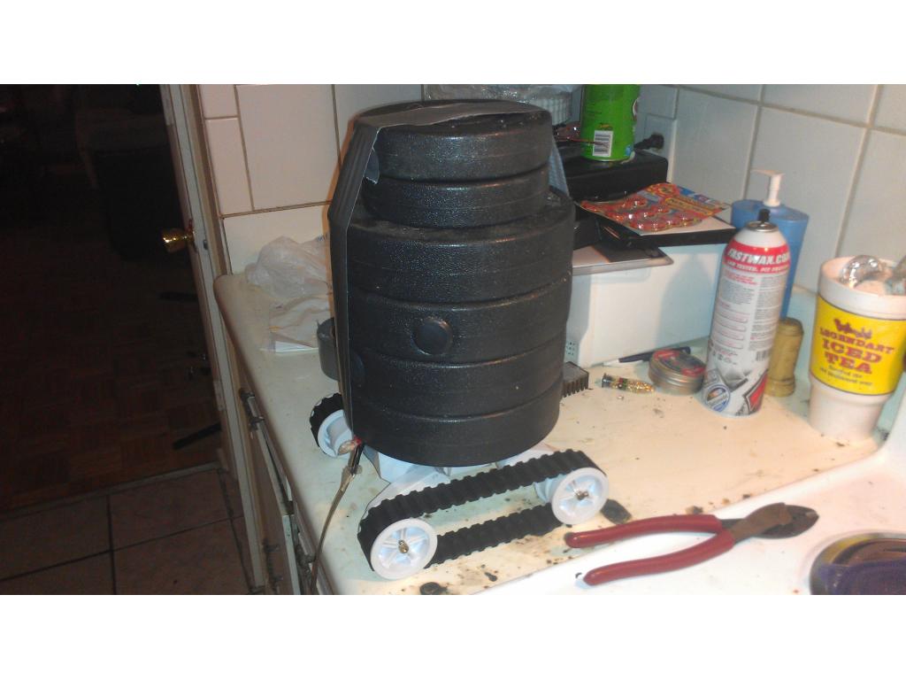
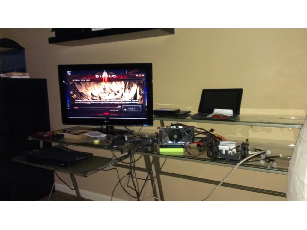
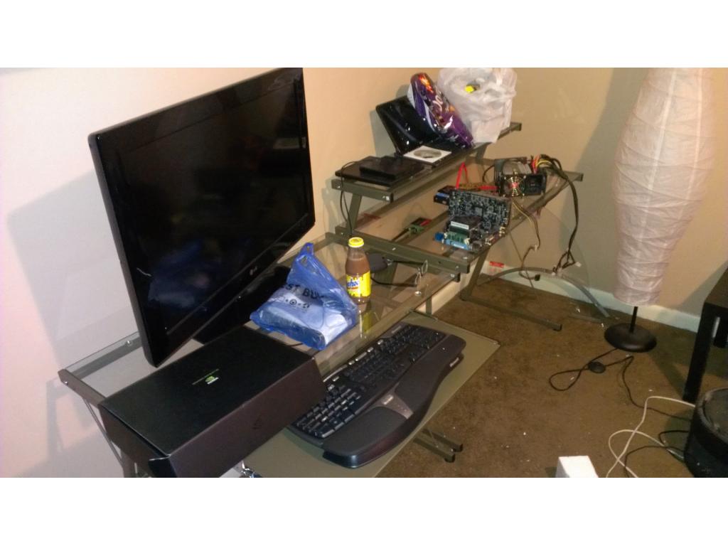

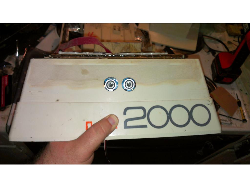
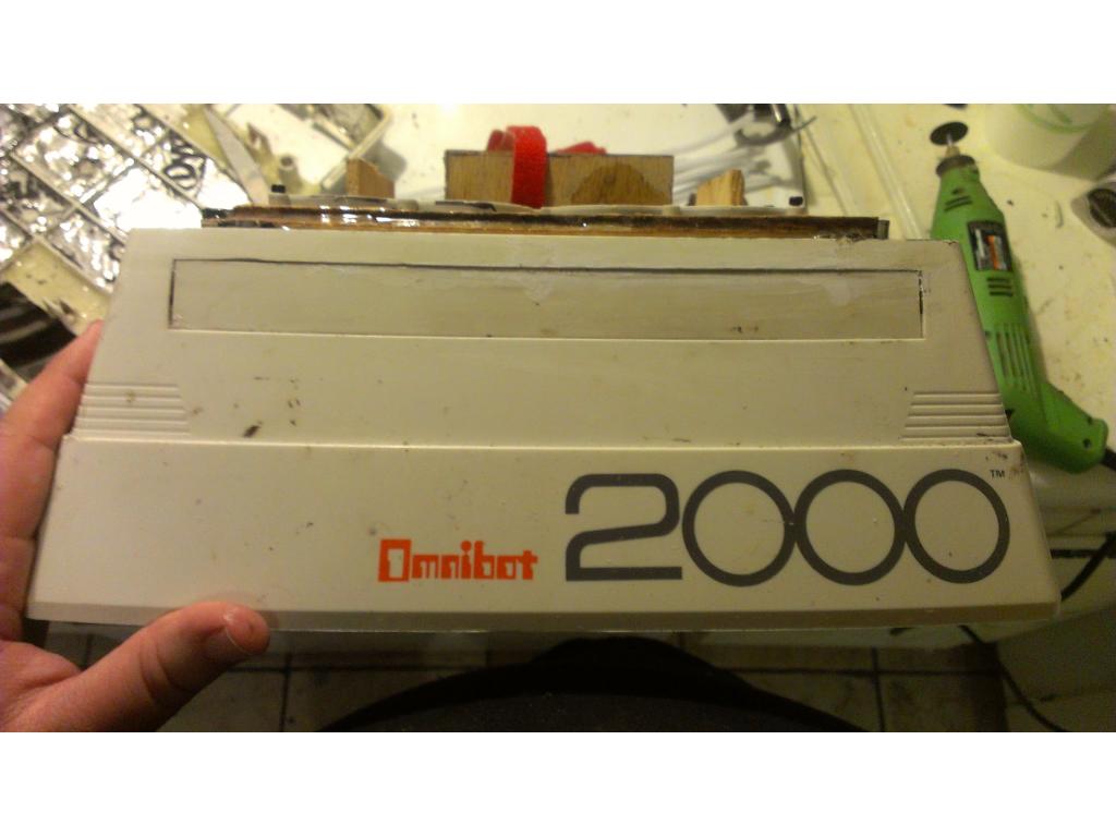
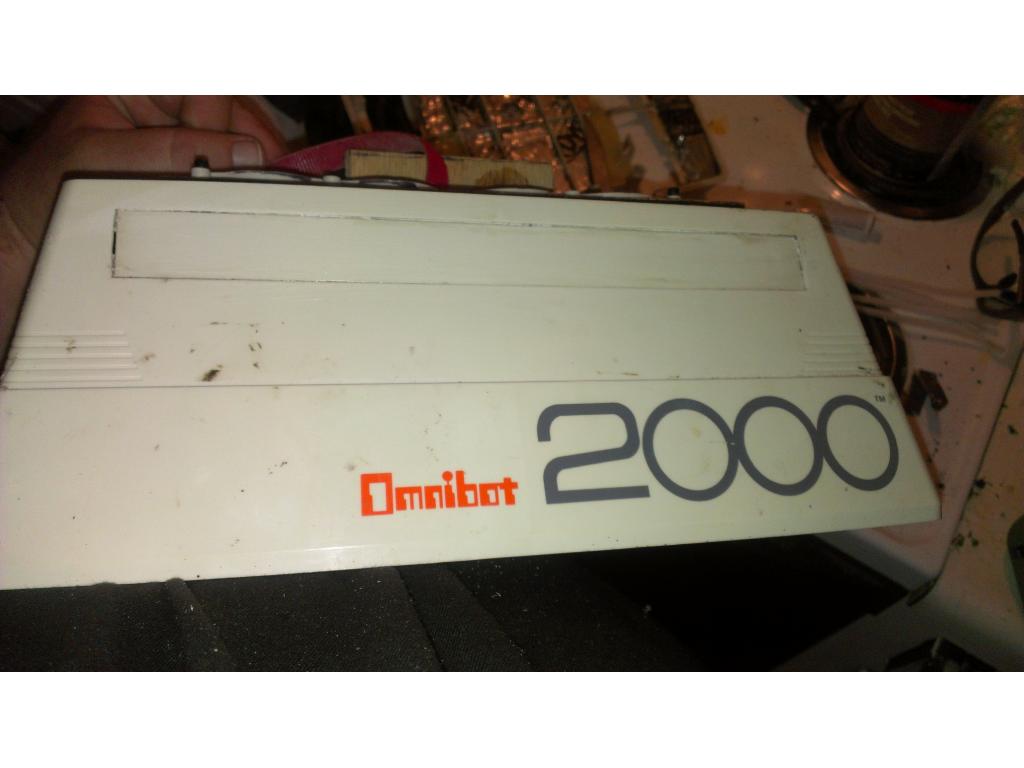
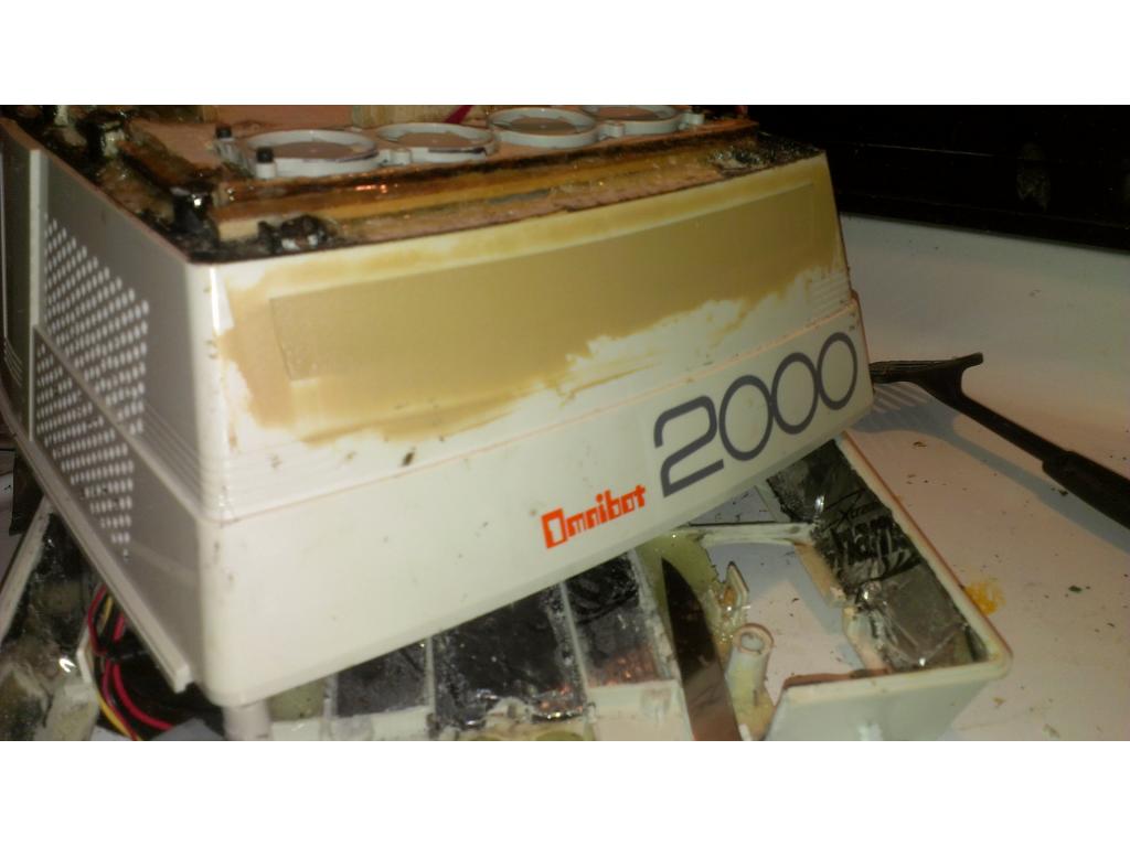

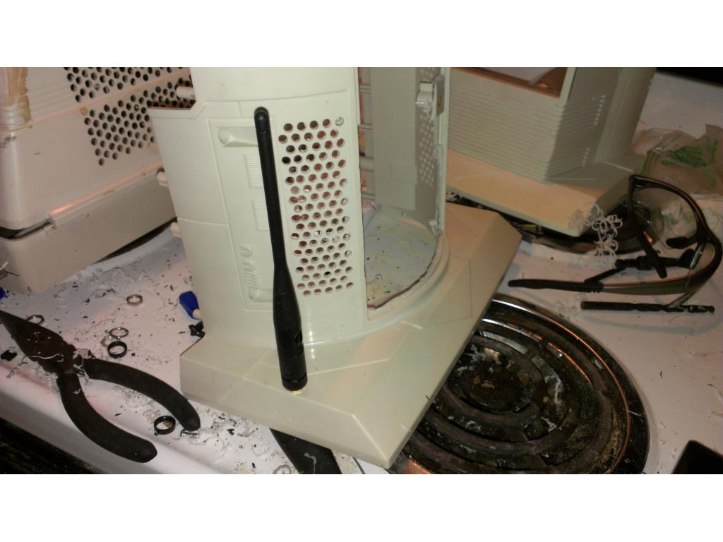
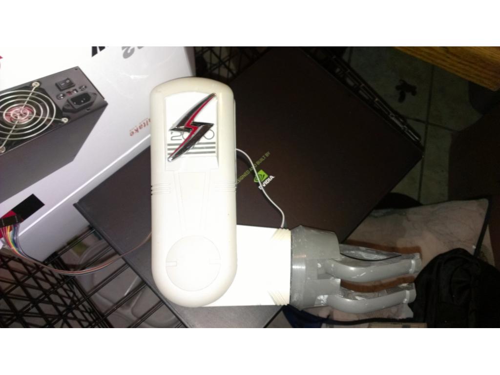
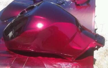
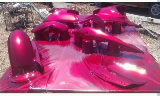
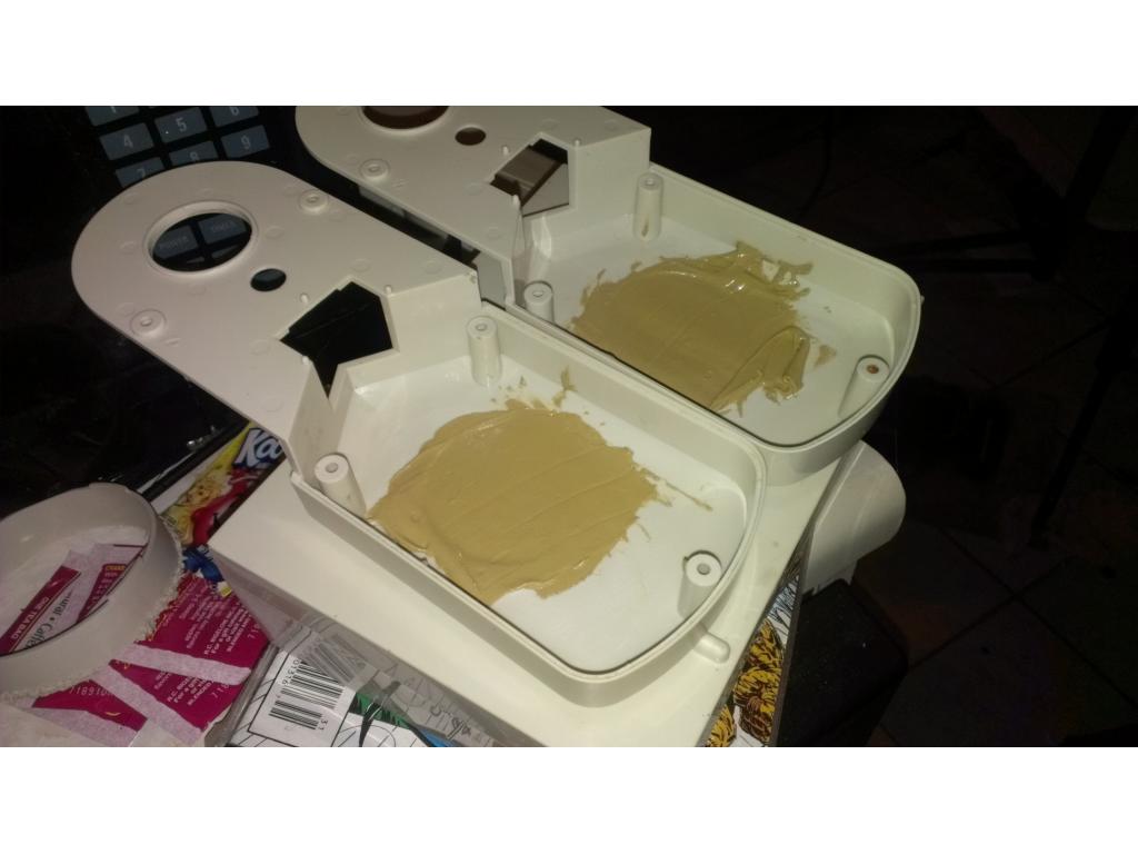


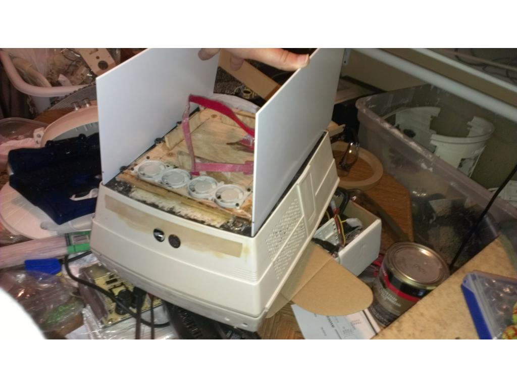
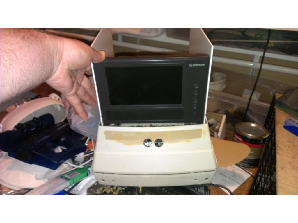
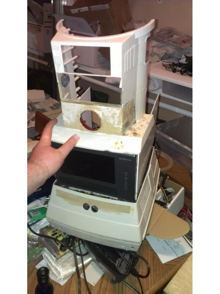
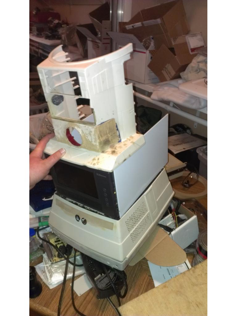
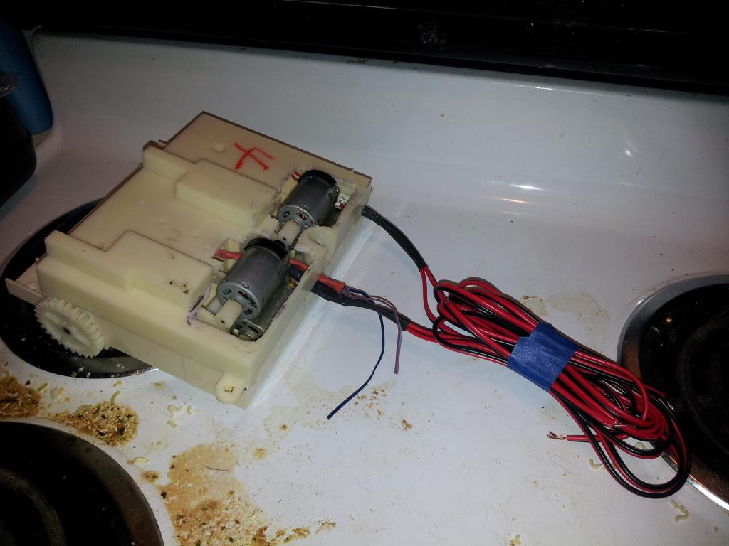
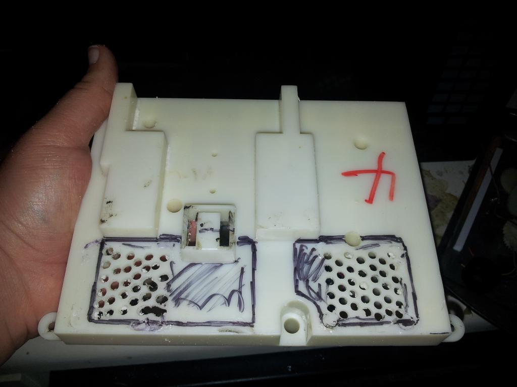
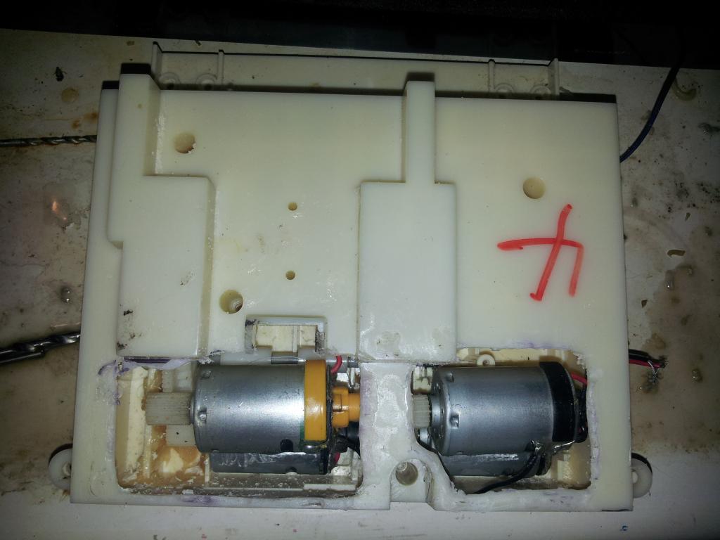
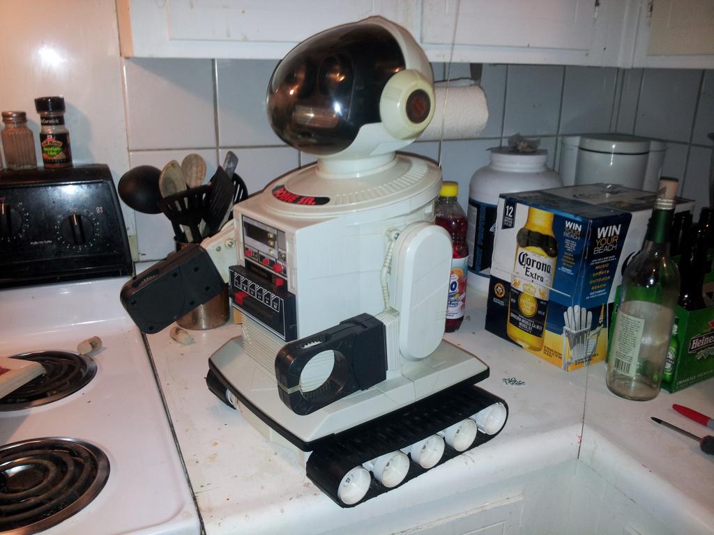
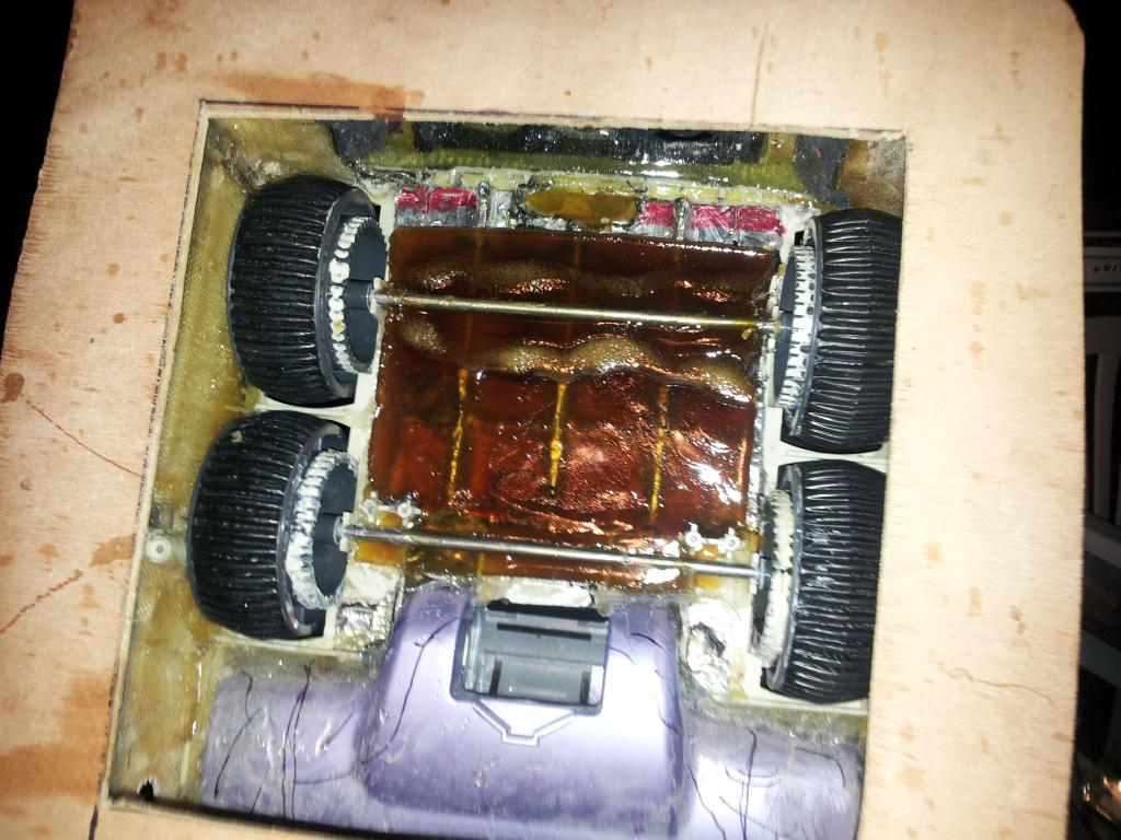
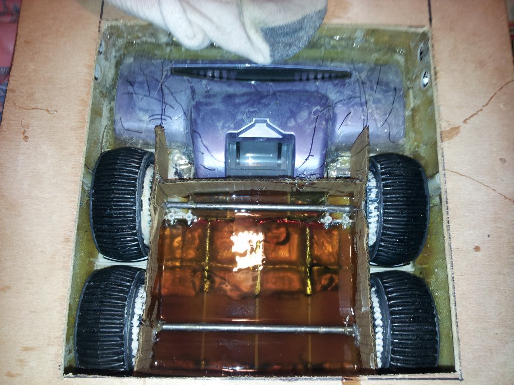
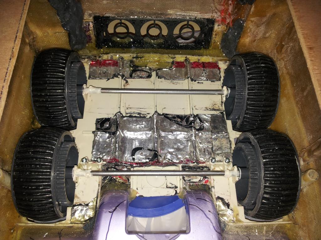
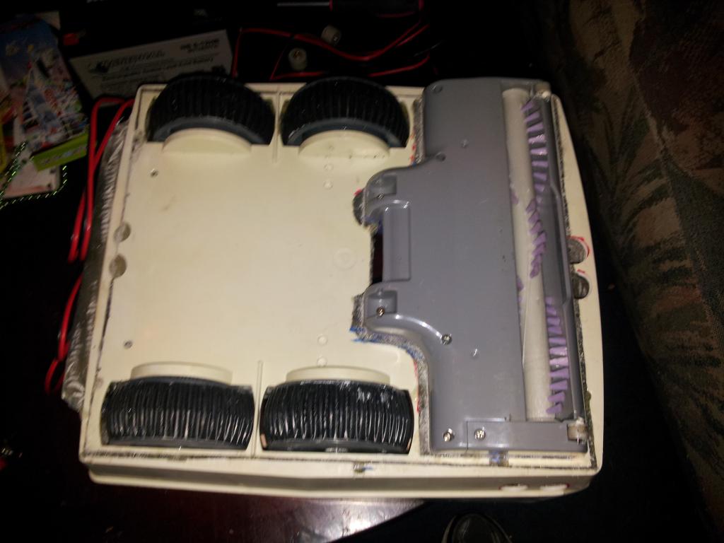
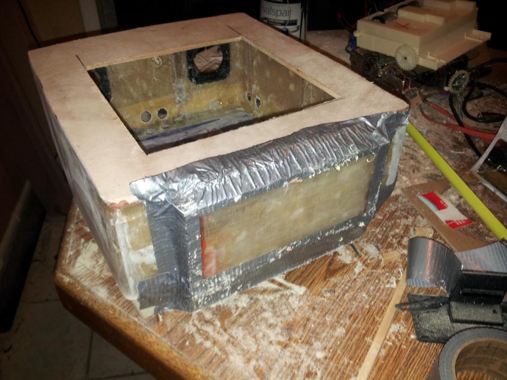
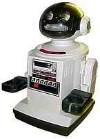
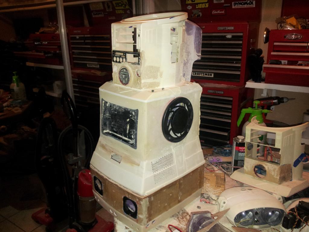
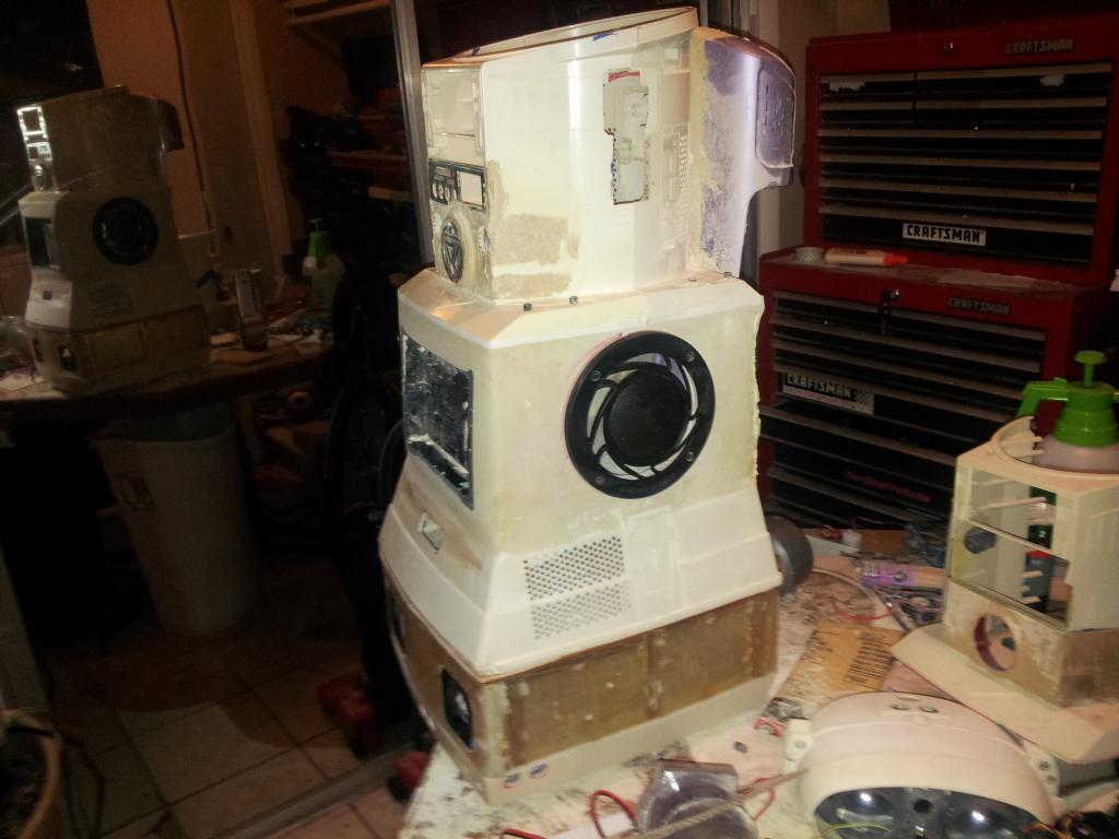
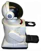
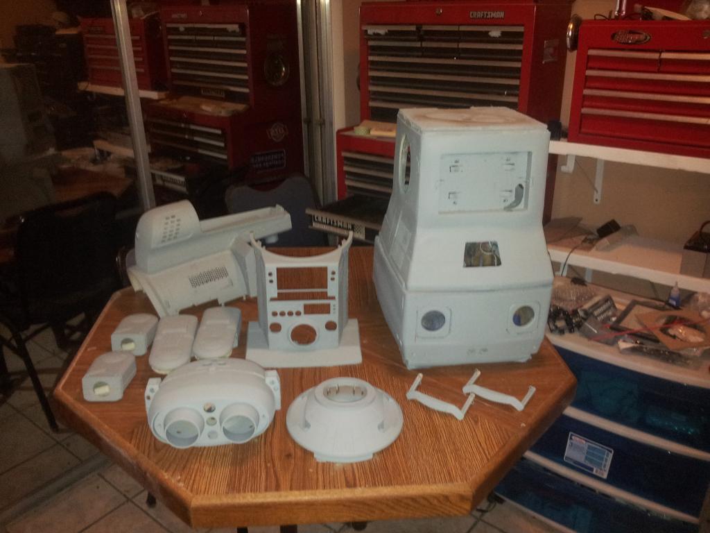
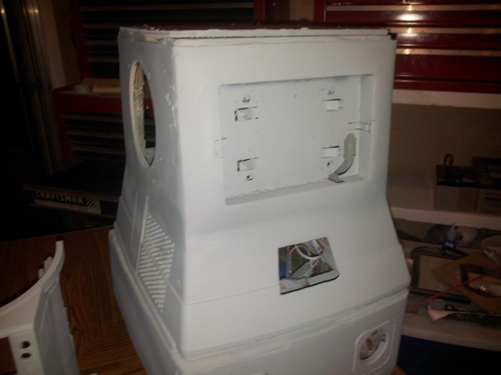
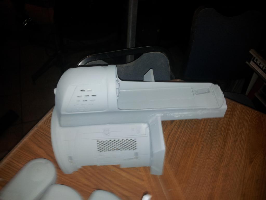
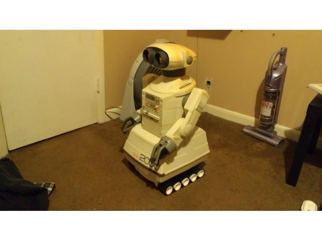
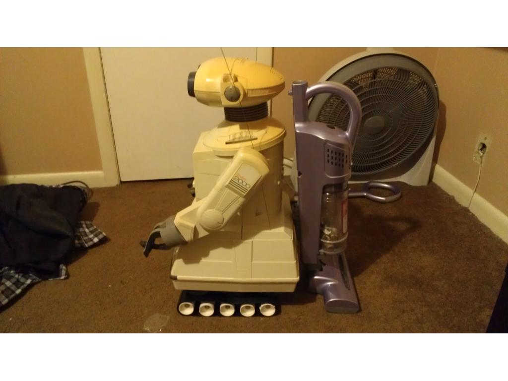
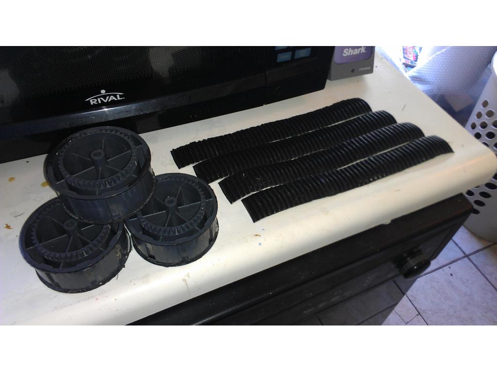
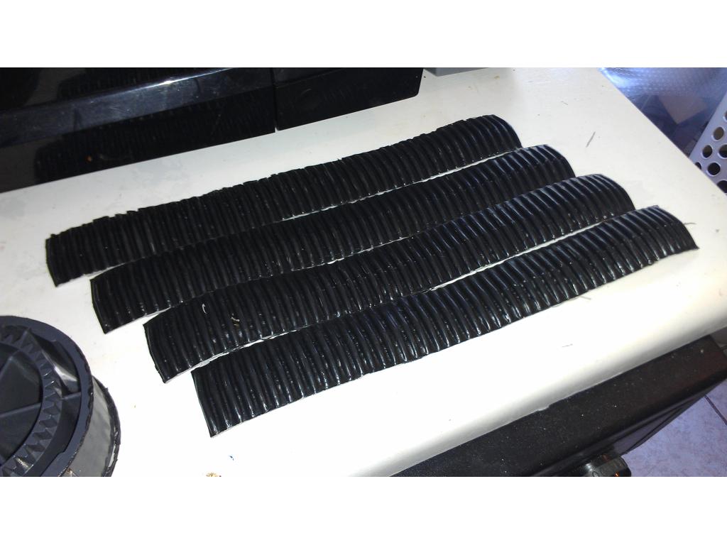
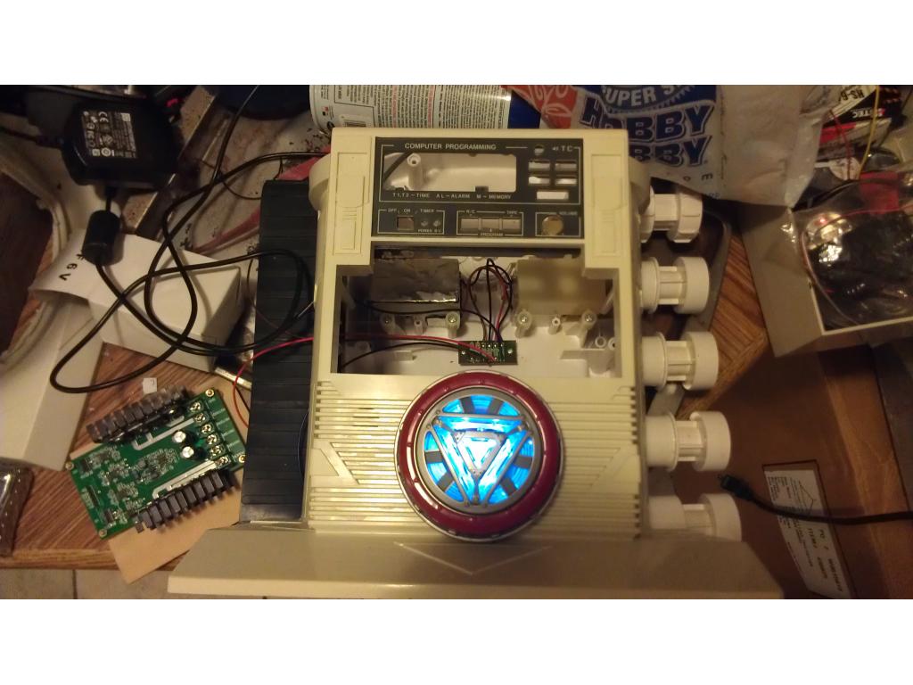
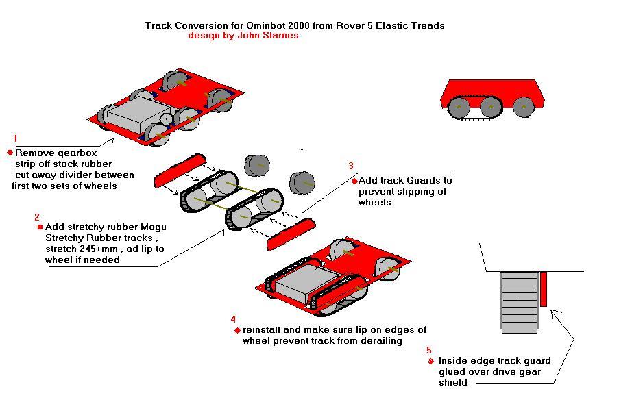
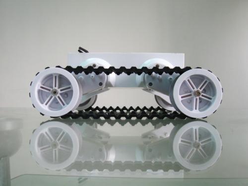
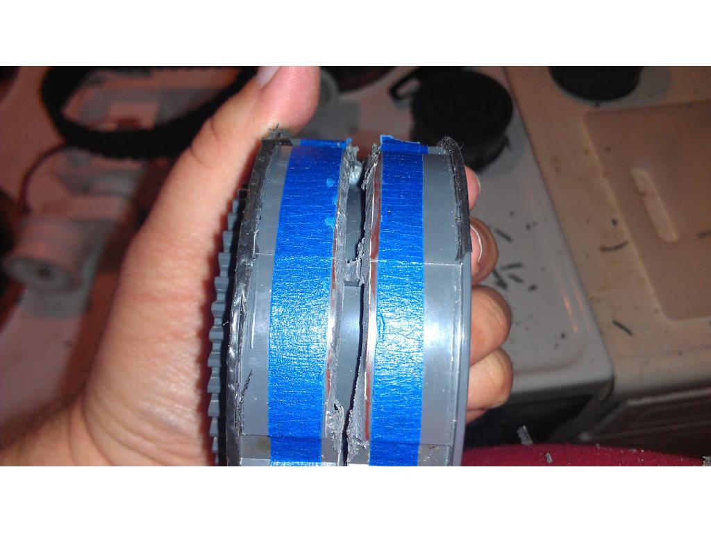
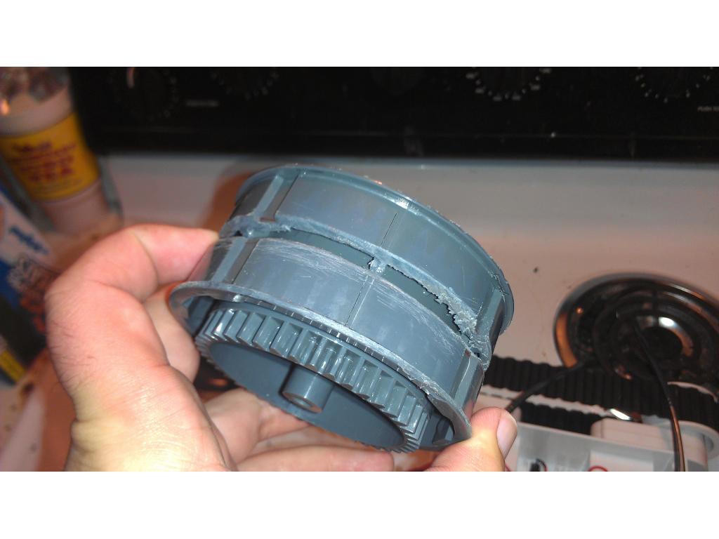
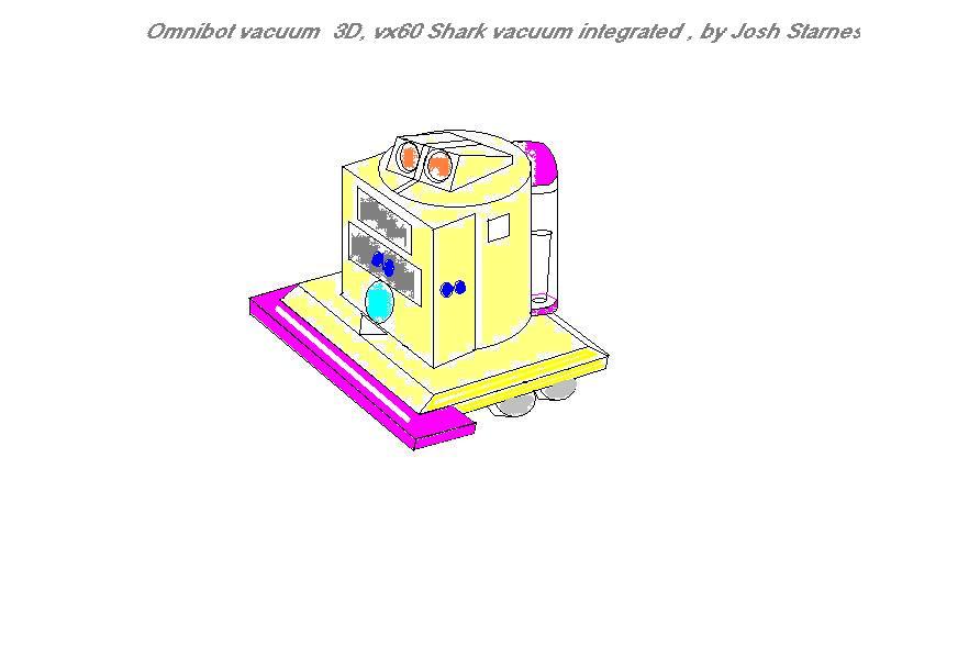
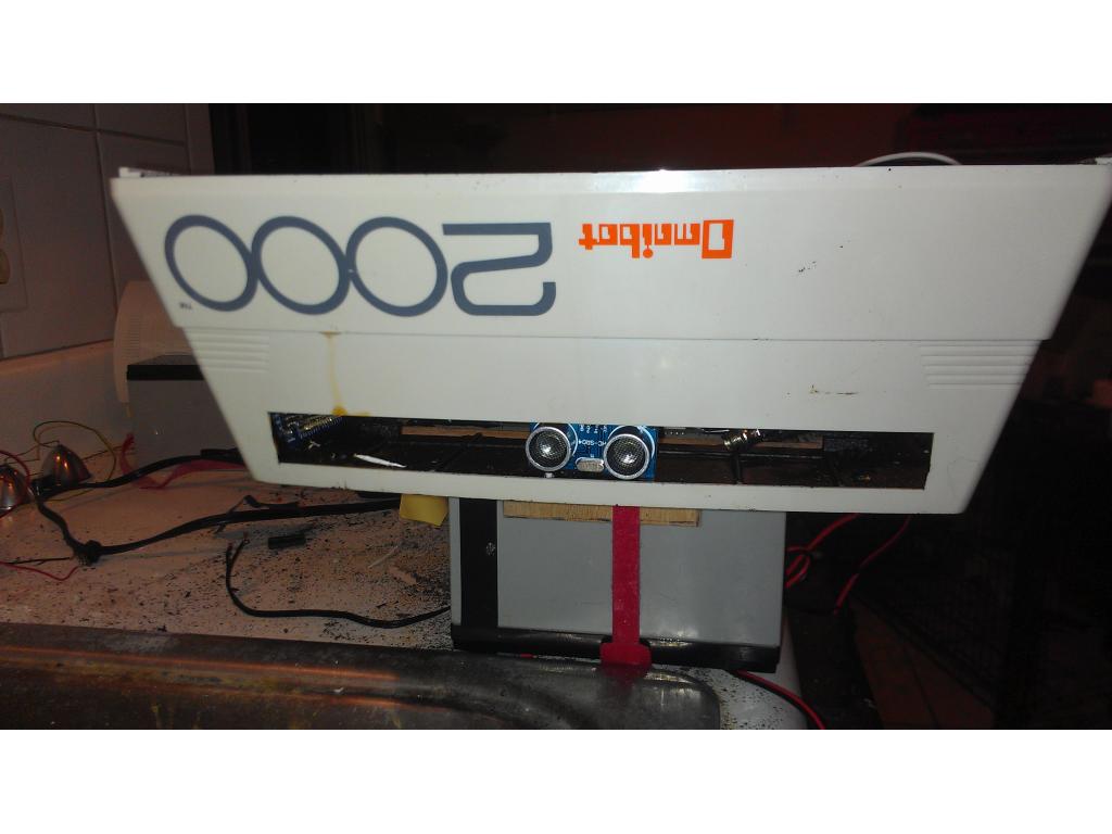
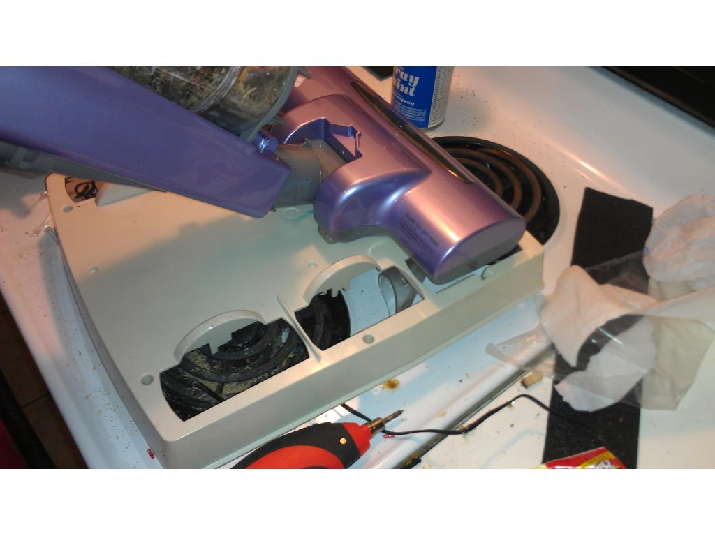
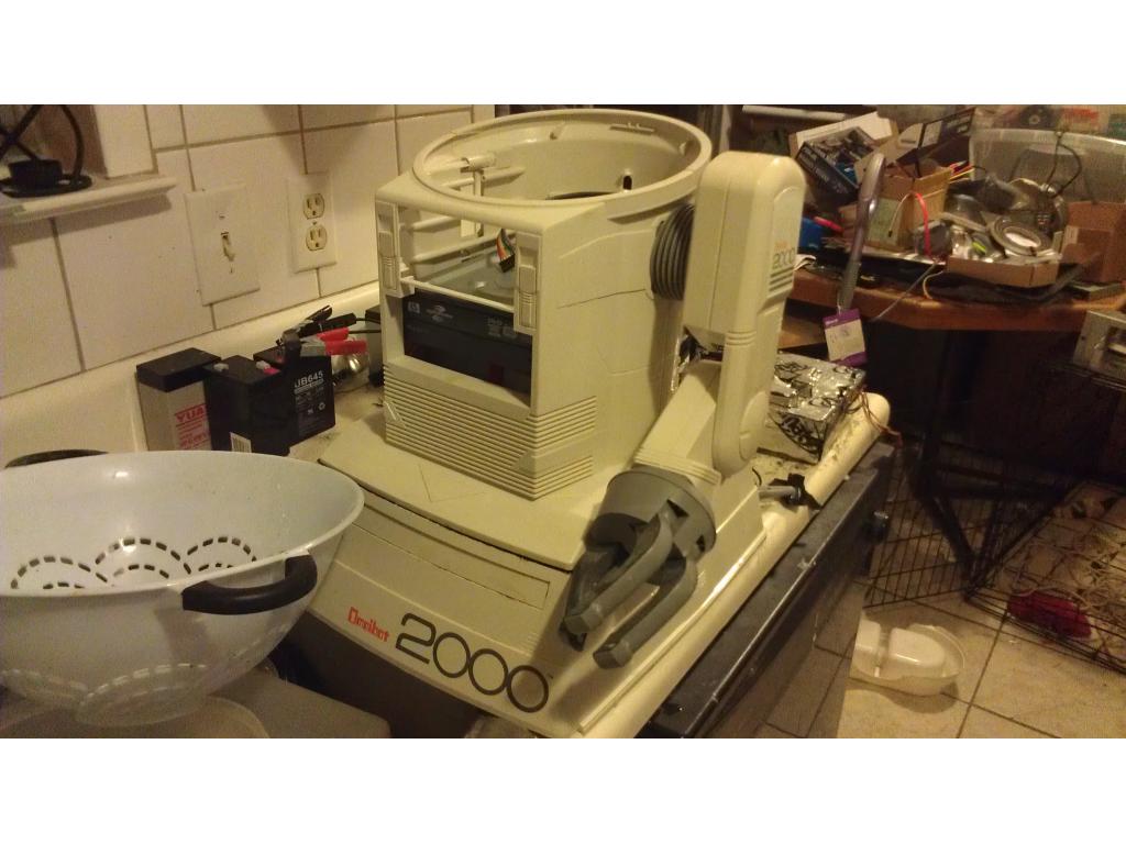
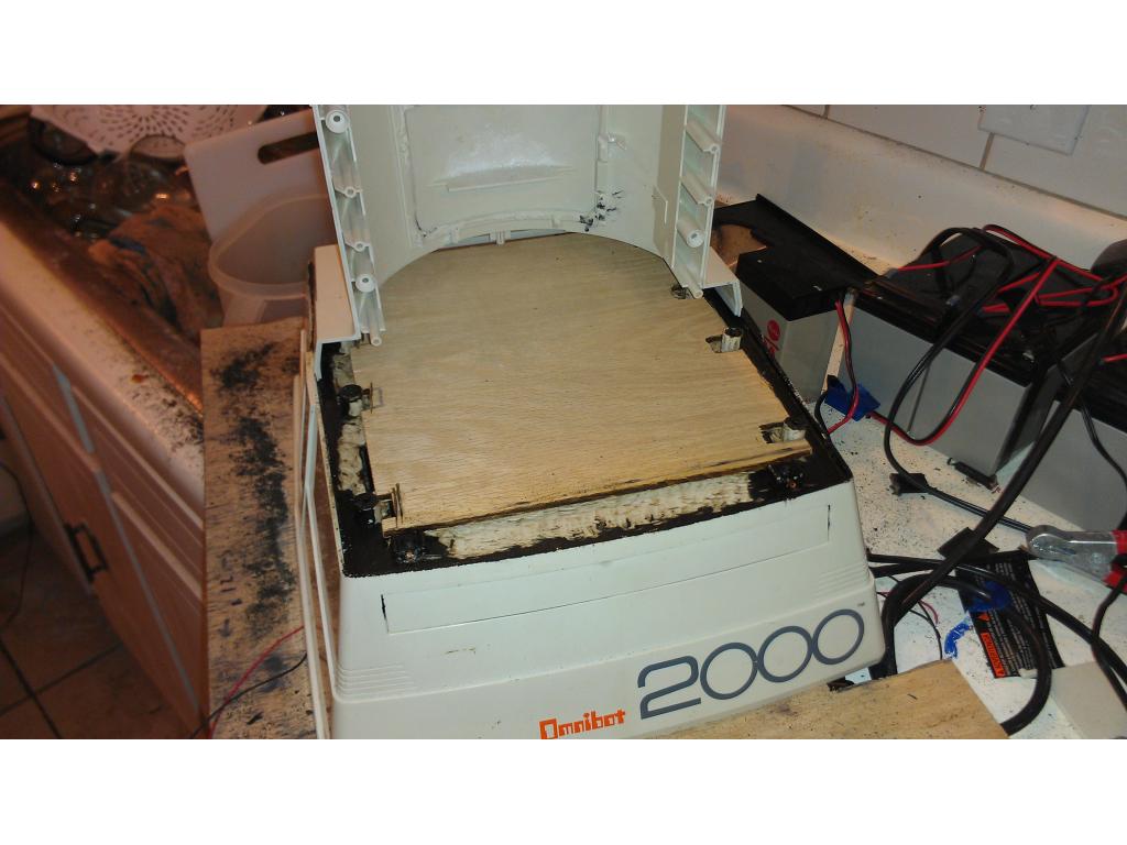
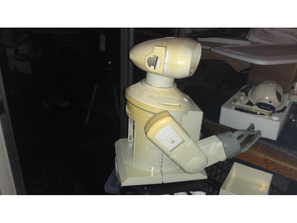
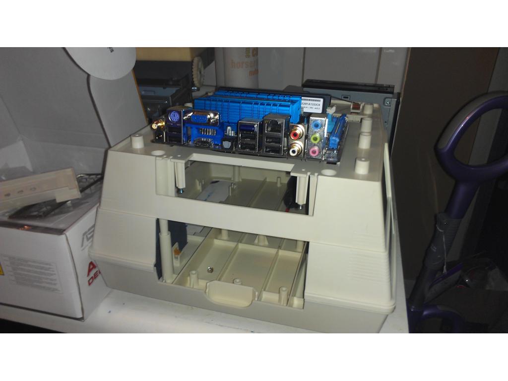
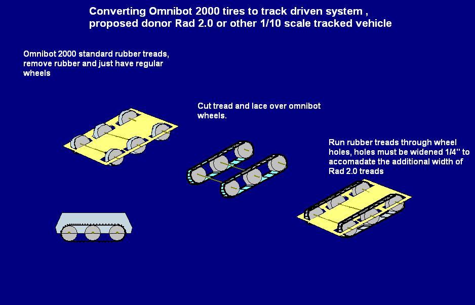
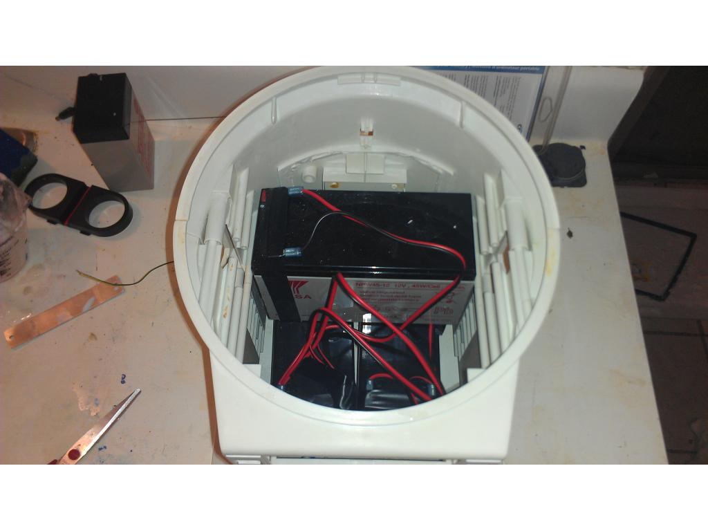
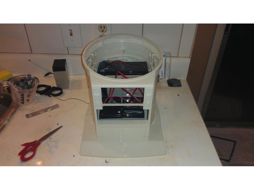
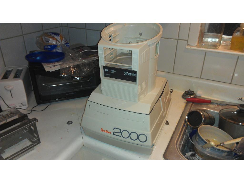
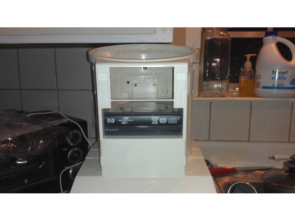
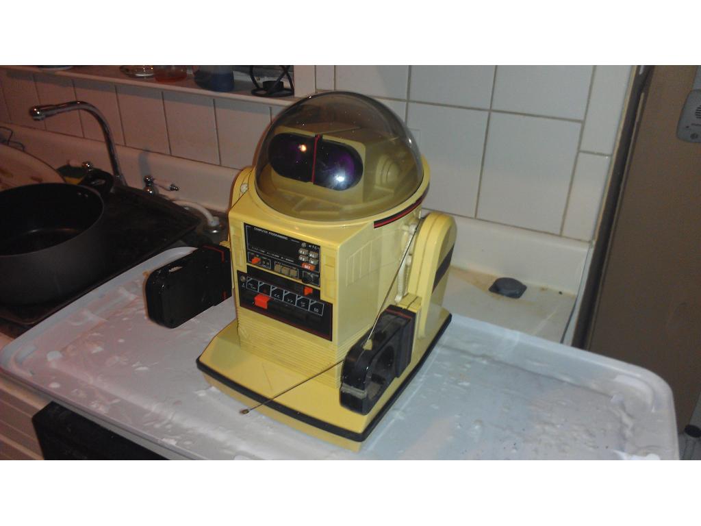
This project has evolved some , the basic rundown is I'm modding two Omnibots , one a regular the other a larger 2000 model. I will have two ezb kits , rad base idea was thrown out because of so much noise but could go back on the table if the omnibot drivetrain is too weak to pull it.

By jstarne1
— Last update
Discover more robots

Zxen's My First Robot: Eve
Robomannequin Eve: She's my first.
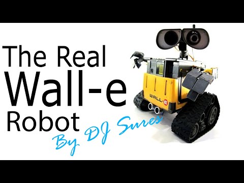
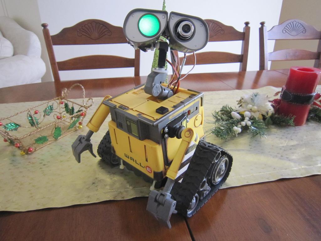
DJ's The Real Wall-E
Real-life Wall-E built with EZ-B Robot Kit uses camera, servos and voice to track motion, color and faces and react with...
Mereyes's Mereyes WALL-E
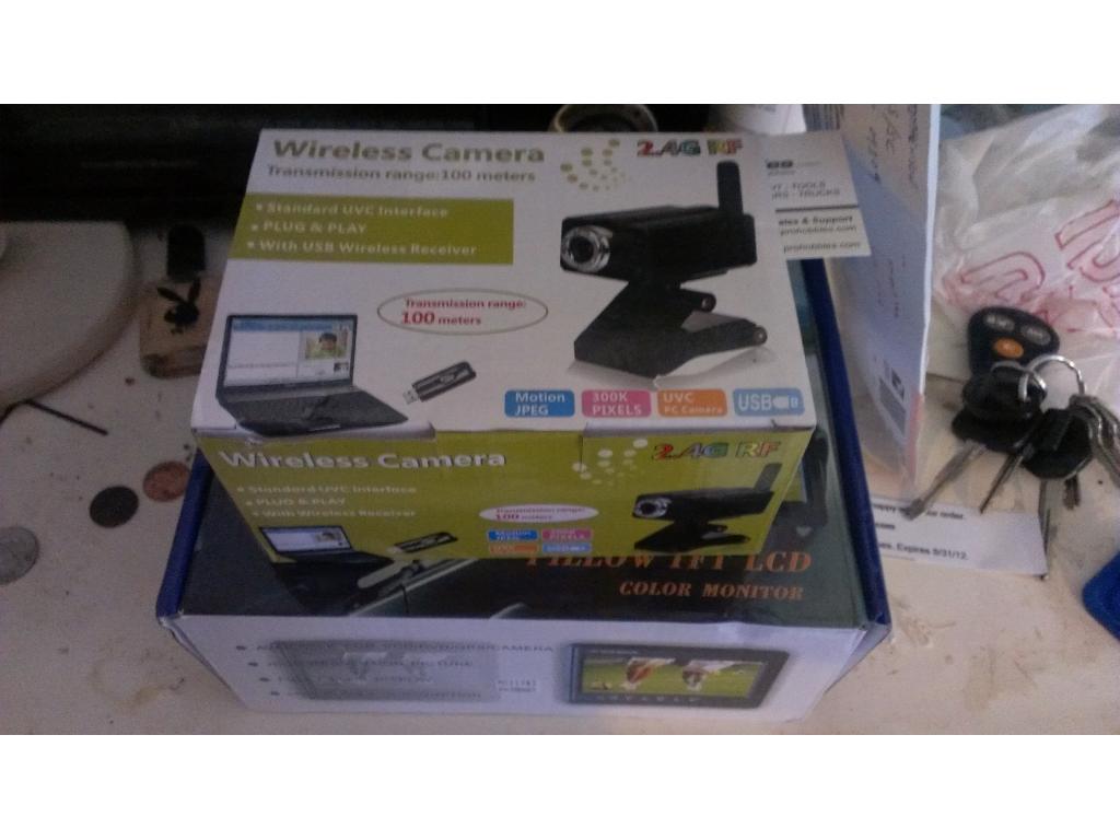
WallE replica using EZB v3 controller: wheel/arm/head servos, BlinkM eye, 2.4GHz camera, SparkFun MP3 trigger, 6V...

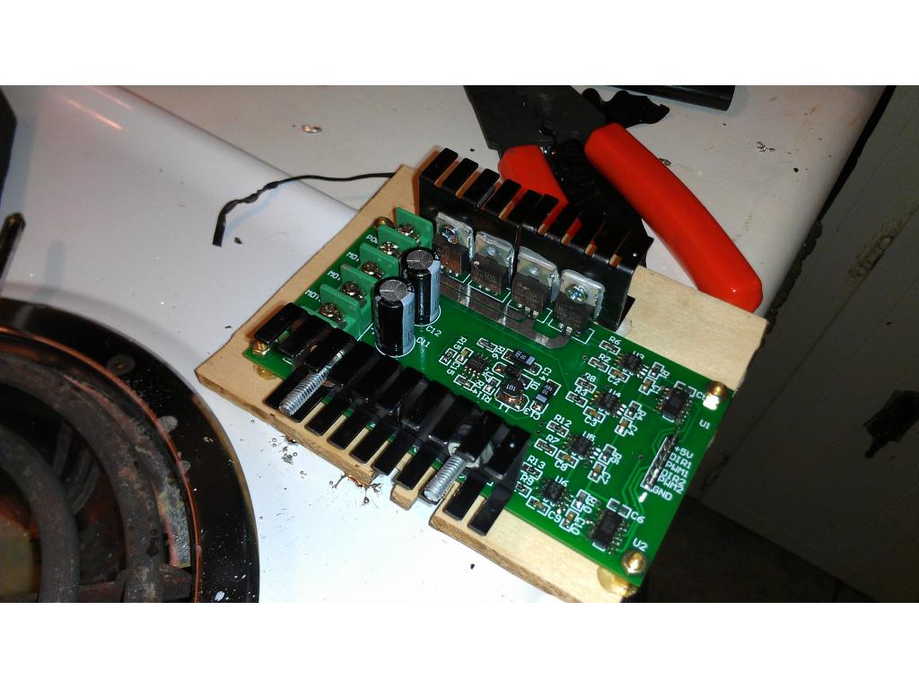
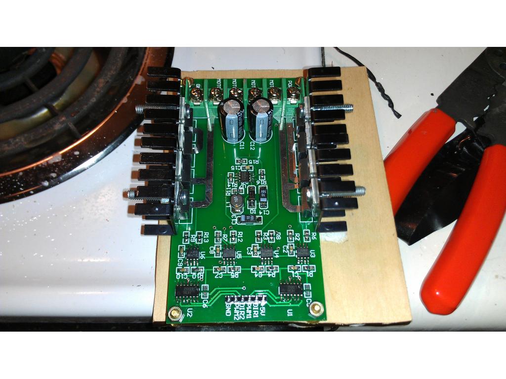
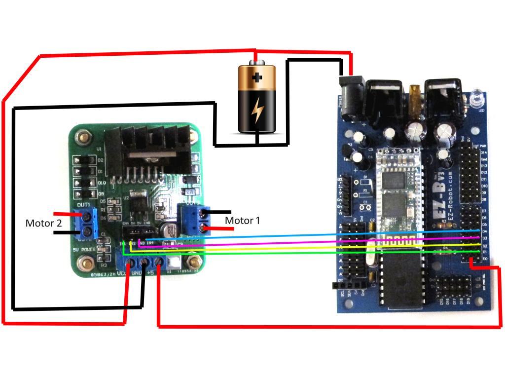
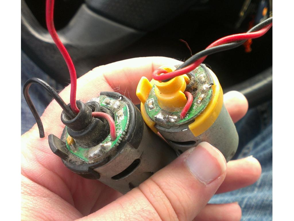
allyour mods look fairly good,but some could be better check robotshop.com that have all types of h-bridges
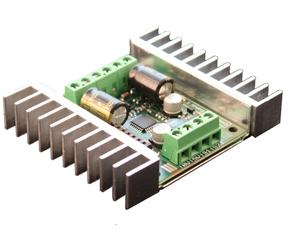
Ok I am shopping for a GOOD H bridge that can handle 10 amps each side as we speak.
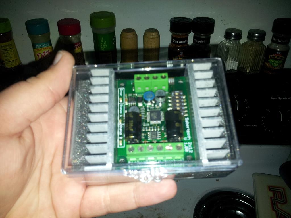
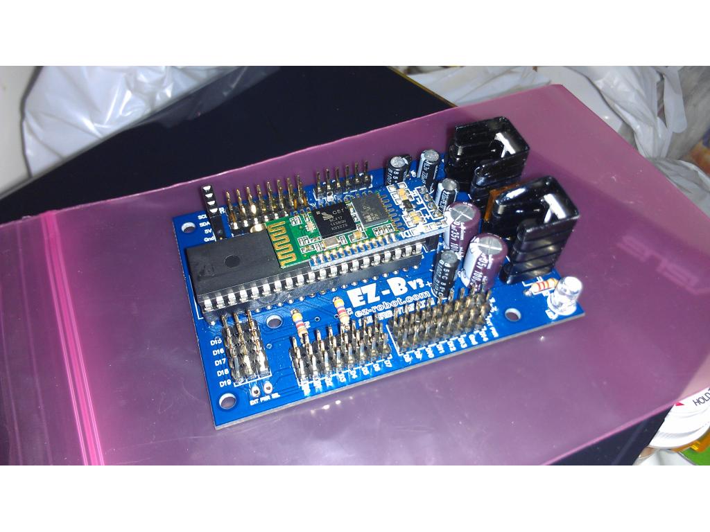
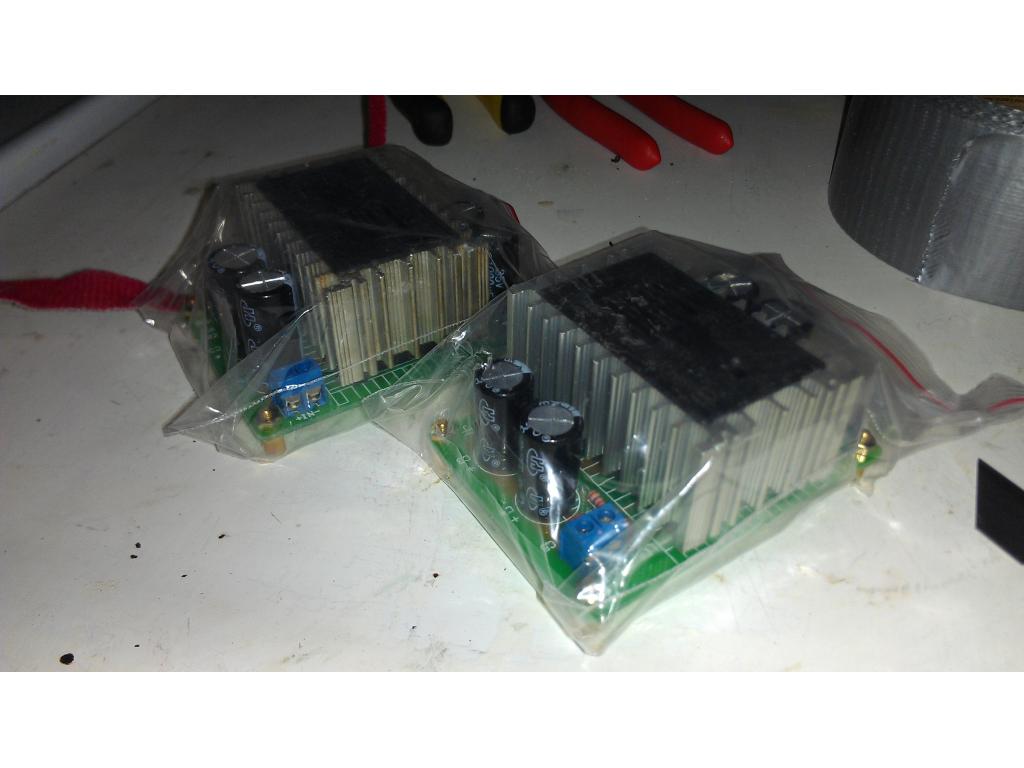
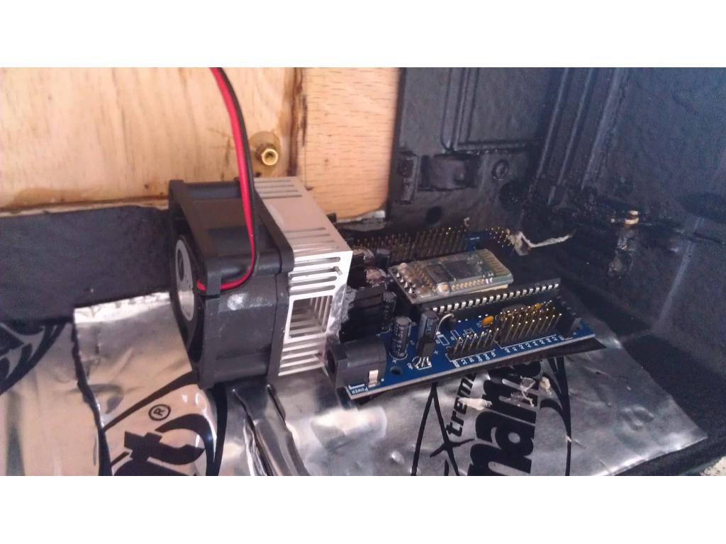
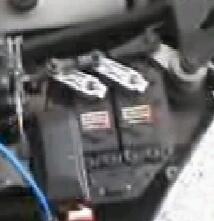
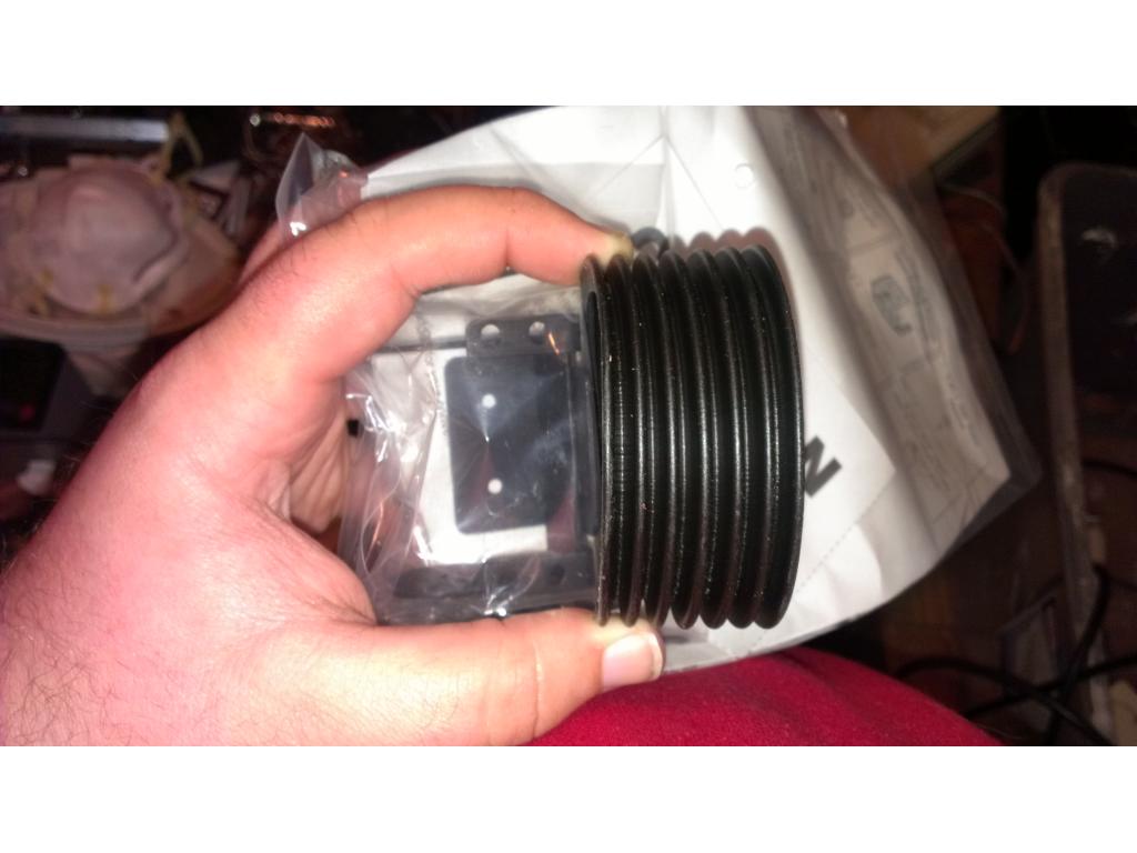
OK I contacted Dimension Engineering the maker of Sabertooth Controllers and Told them about the Project. They are sending me a New controller that replaces the 2x10 . It is the Sabertooth Robotics 2 x 12 H bridge, They said they would recomend it for robots for up to 100 pounds. ( even though I know its not that simple though) Sabertooth allows you to control two motors with: analog voltage, radio control, serial and packetized serial. 12 amp continous operation and up to 25 amps for 8 seconds before it does a thermal shutoff.
I think this will do the trick and thankyou to the guys at Dimension Engineering
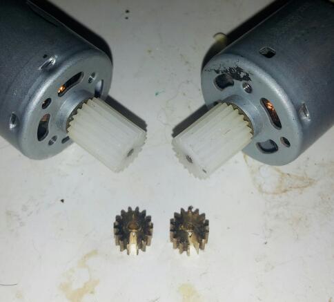
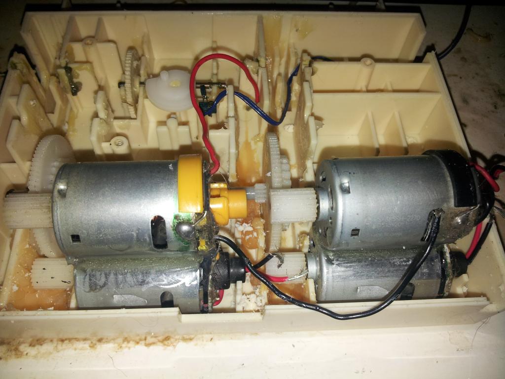
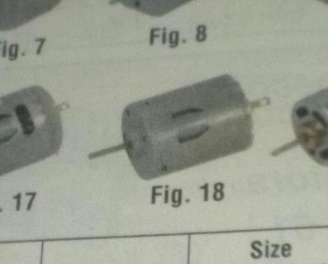
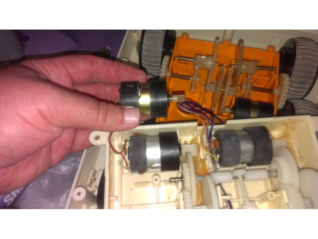
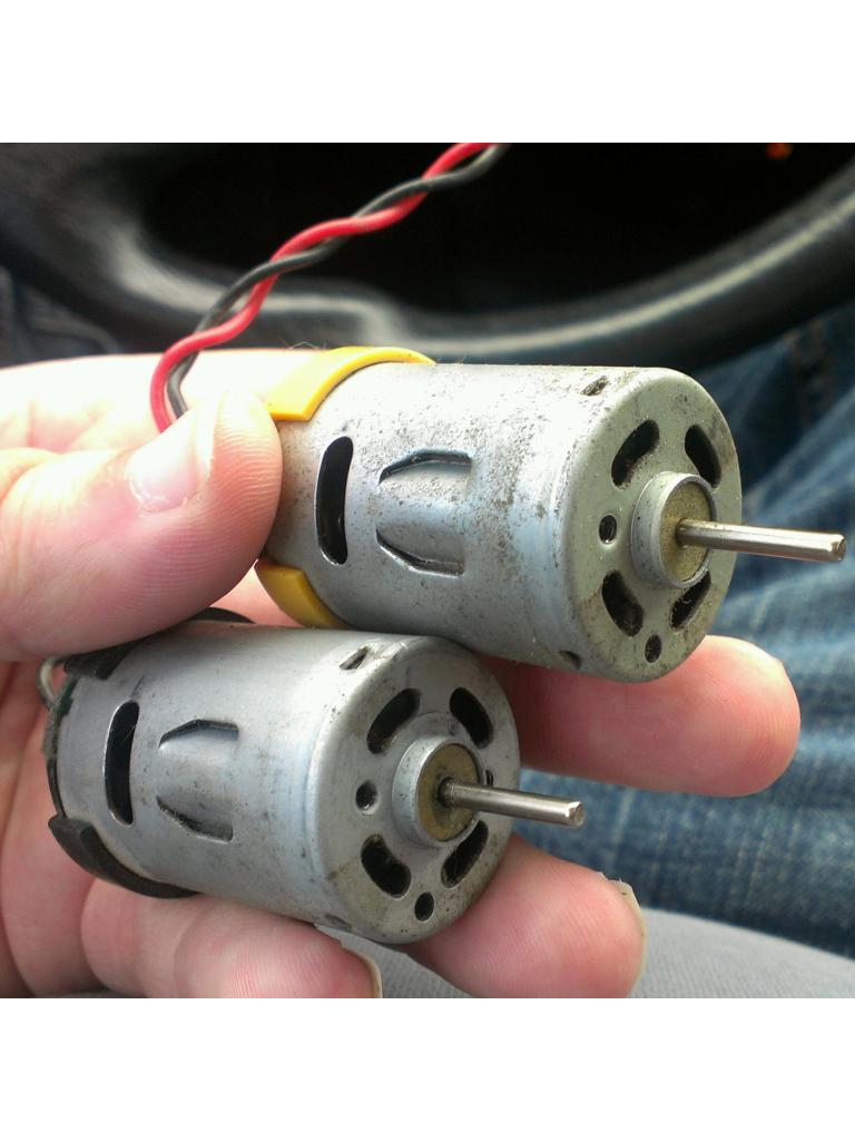
12 AMPS WILL WORK ,but for selecting H-BRIDGES for weight on the they way to ,0 it depends first on the motor stall current,second the gear box ,can have a 25 amp motor to handle 100 lbs too,then the one by dimension engineering will smoke BUT FOR YOUR'S IT SHOULD WORK I would test both motors at stall current,a pro setup for testing is amp meter on the winding,along with temperature probe oon the motor and electronic brake and timer
but a simple test is hold the motor shaft or attach a wheel and stop the motor spinning and reat the current value or use min/max peak meter like the ones i have fluke making a good 4 1/2 digital with that function and more (price is high )
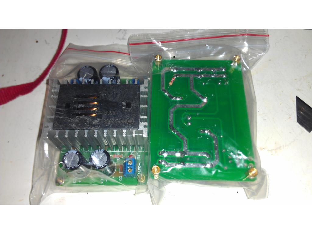
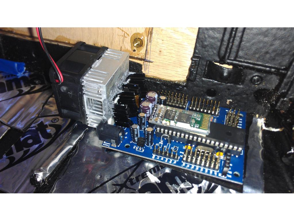
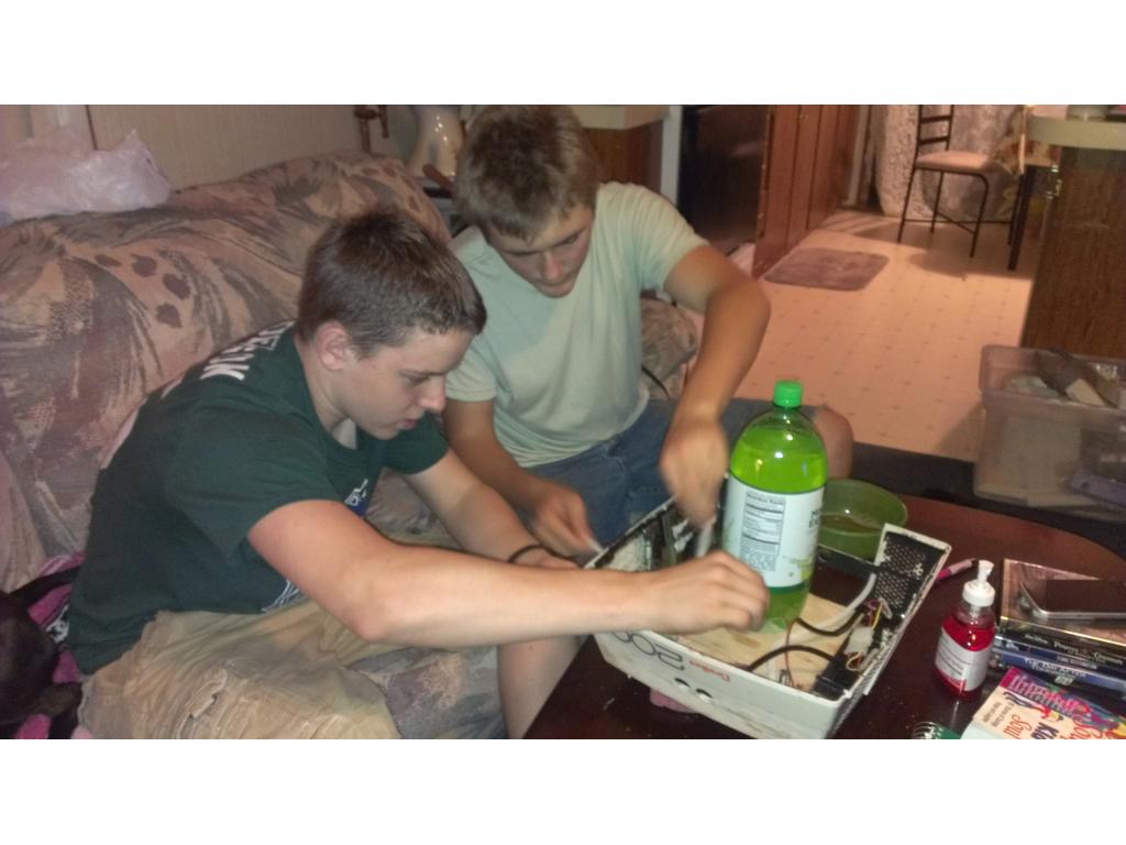
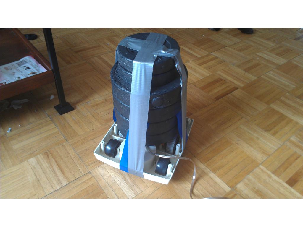
Well they hooked me up for half the price of the 2 x 25. The 25 amp seemed overkill. I was going off your information I needed a 10 amp and they hooked me up with a 12a continuous 25a burst for 8 seconds. IM betting this will work great! I can't wait to load down that base with 50 pounds and run it around the house.
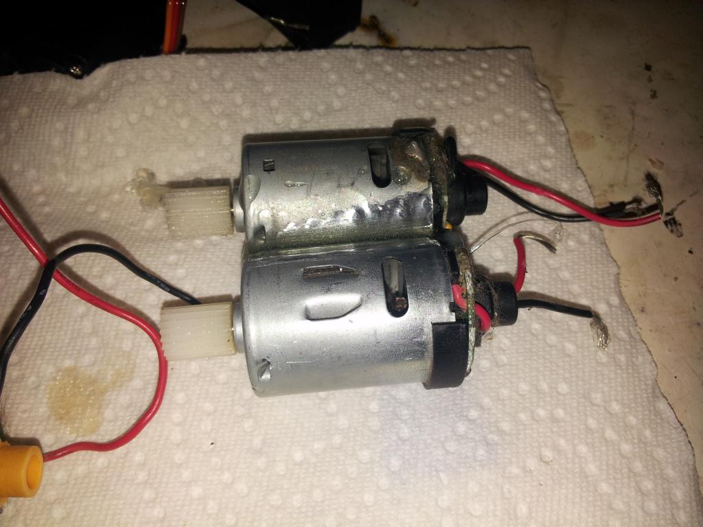
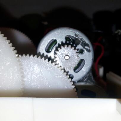
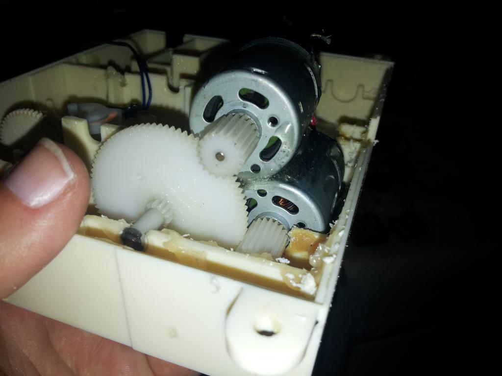
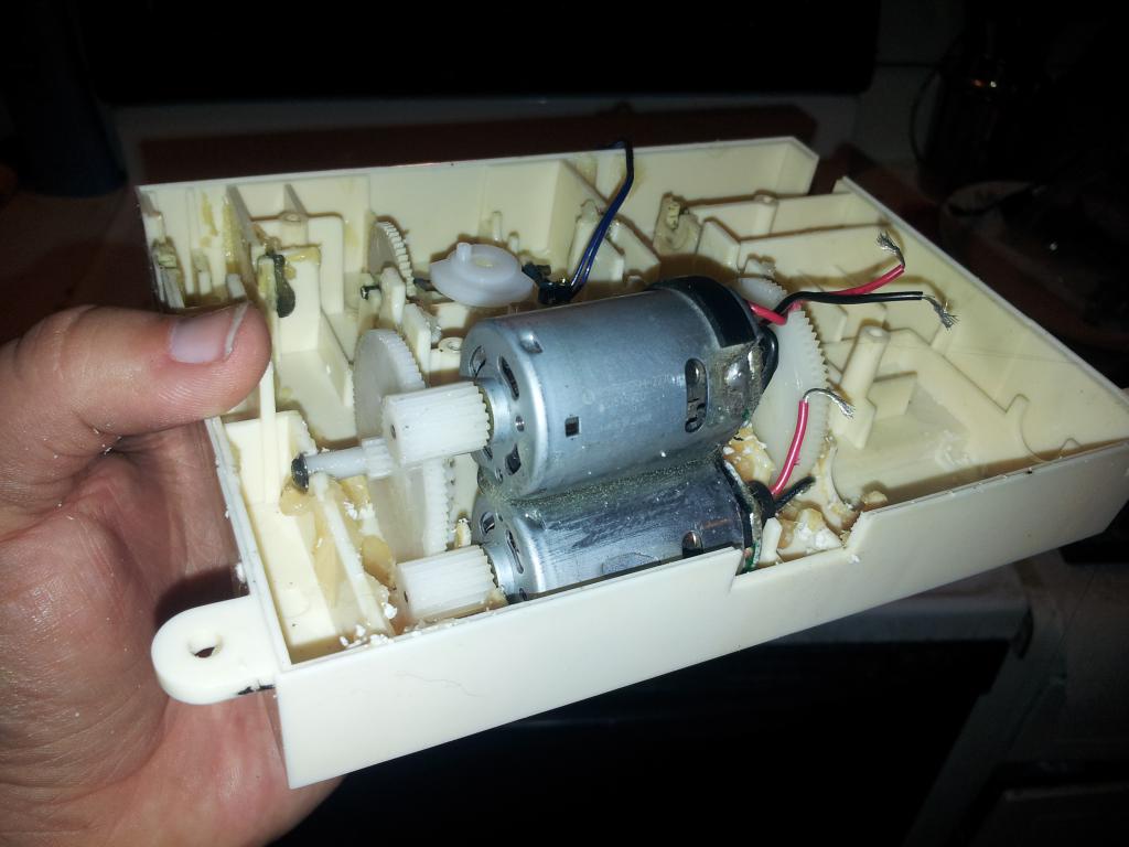
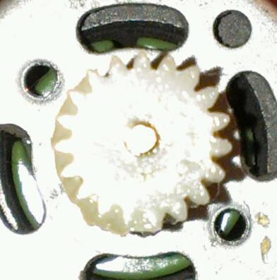
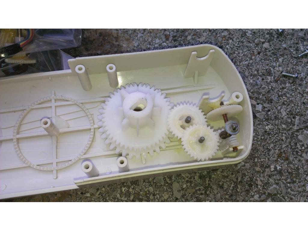
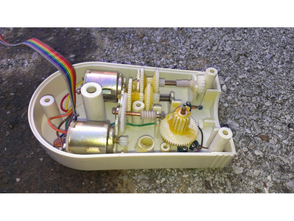
yes i think it will great , 25amp burst for 8 seconds will smoke the board if the wheels get stuck main reason for stall protection if the motors get stuck,or a gear messes up,since they are plastic and wont work very long
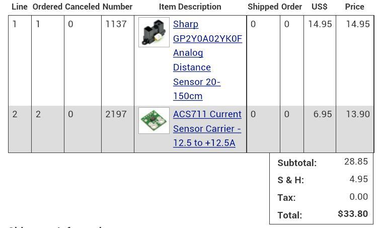
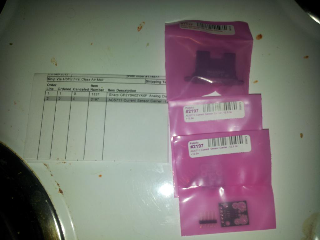
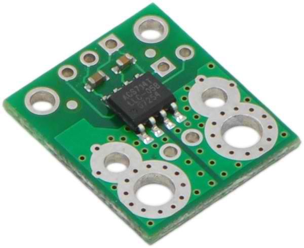
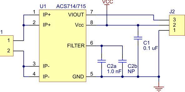
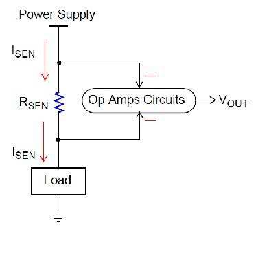
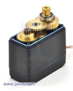
so how to fix this problem,simple add a 10amp current sensor to shut off the motors or brake i guess another order to pololu,since the have a perfect current sensor 12.5 amp best place is inline with main power ,beacuse on motors have reverse power wires it is +/- 12amp current sensor ,so may give the correct voltage out in forward or reverse
Looks awesome Josh...
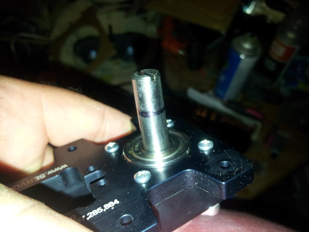
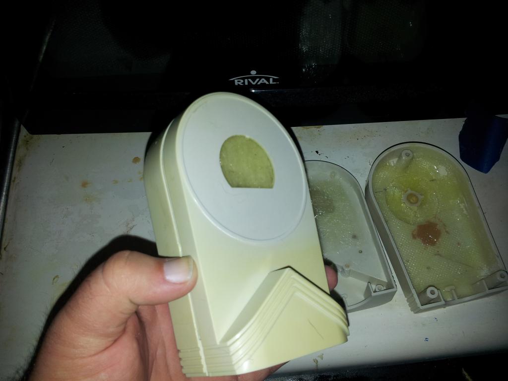
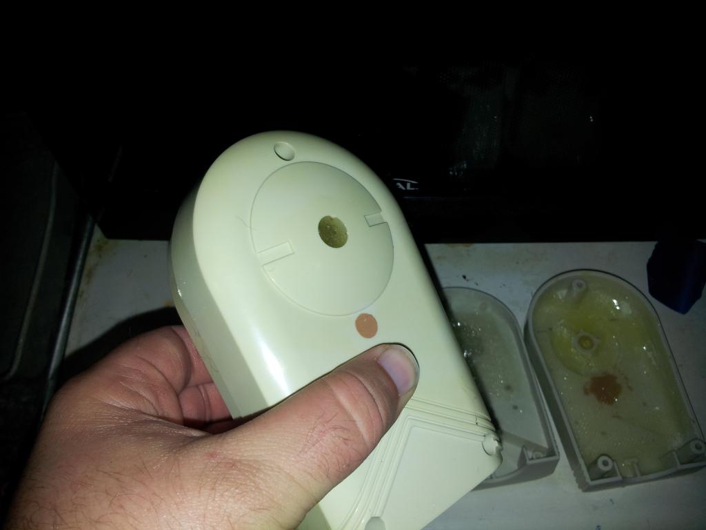
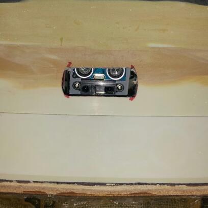
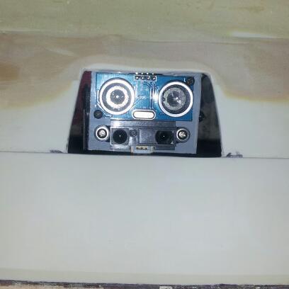
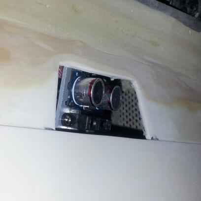
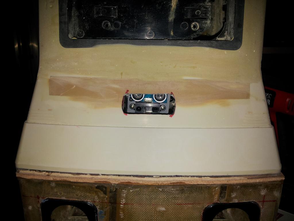
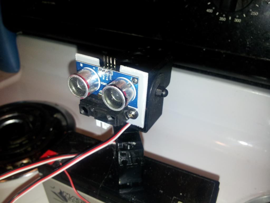
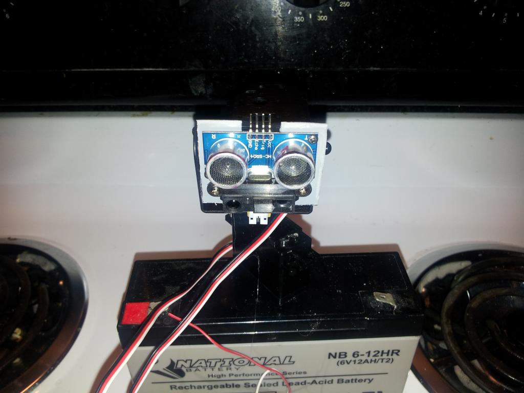
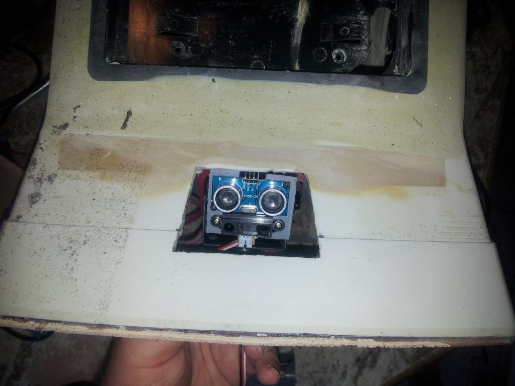
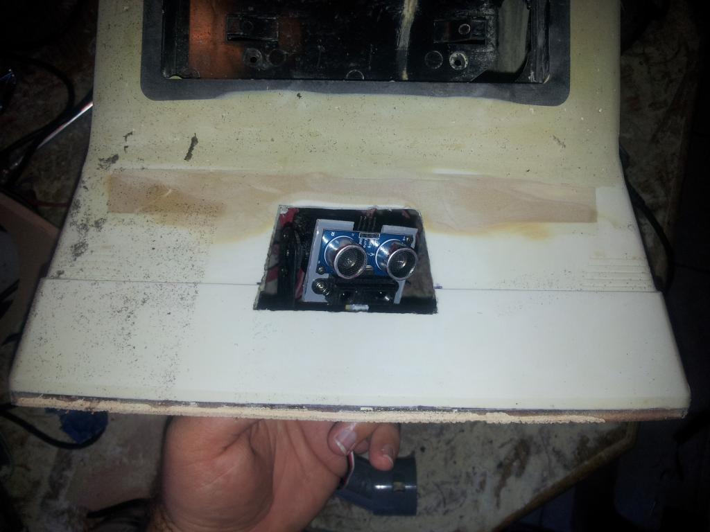
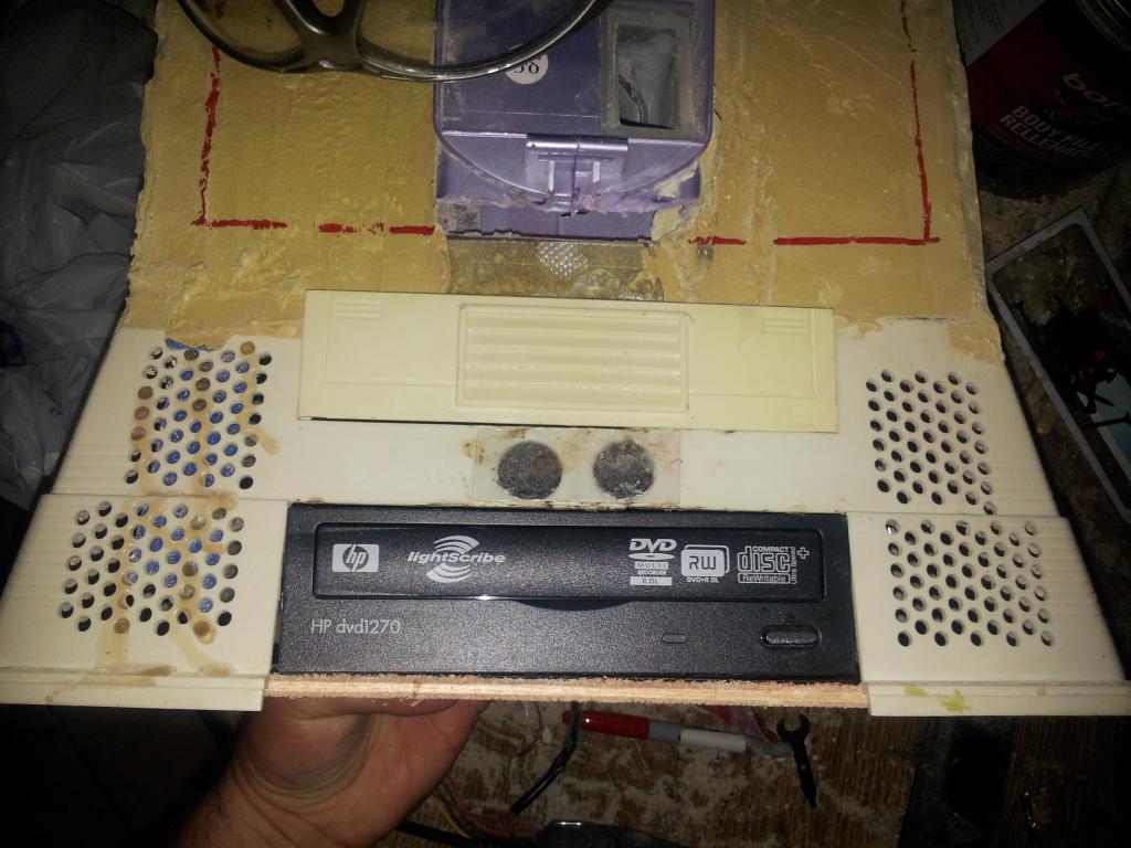
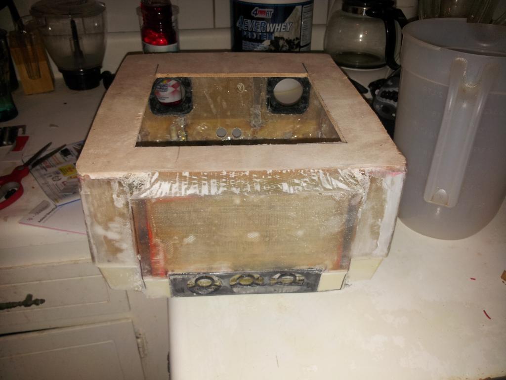
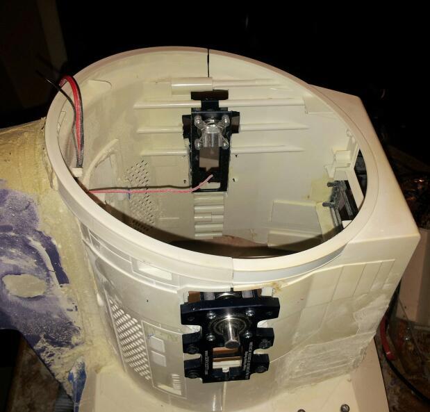
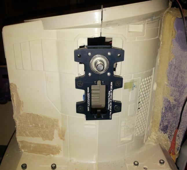
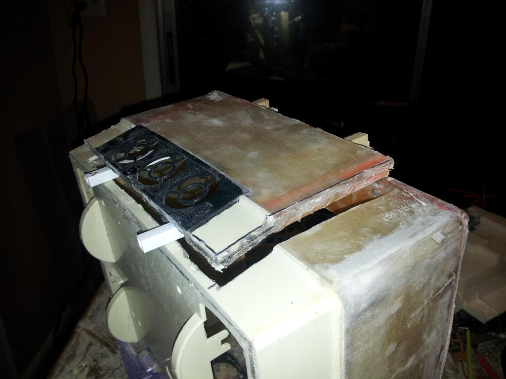
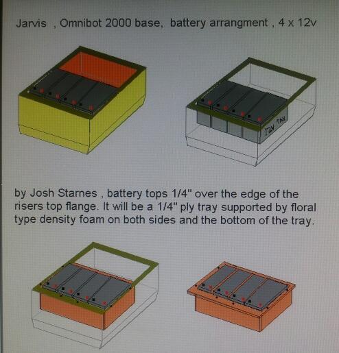
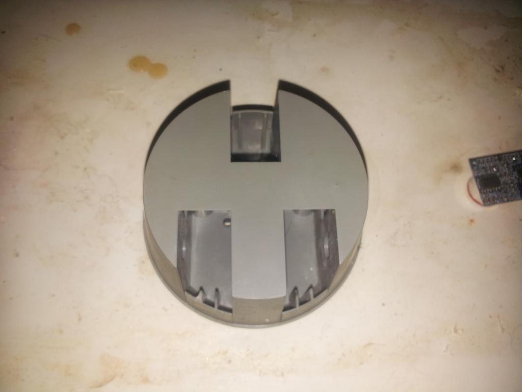
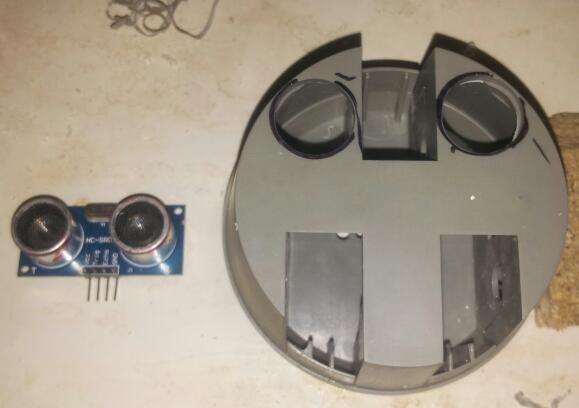
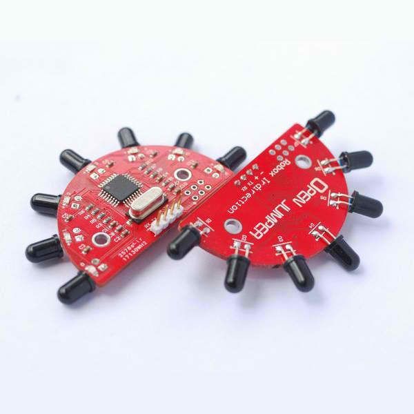
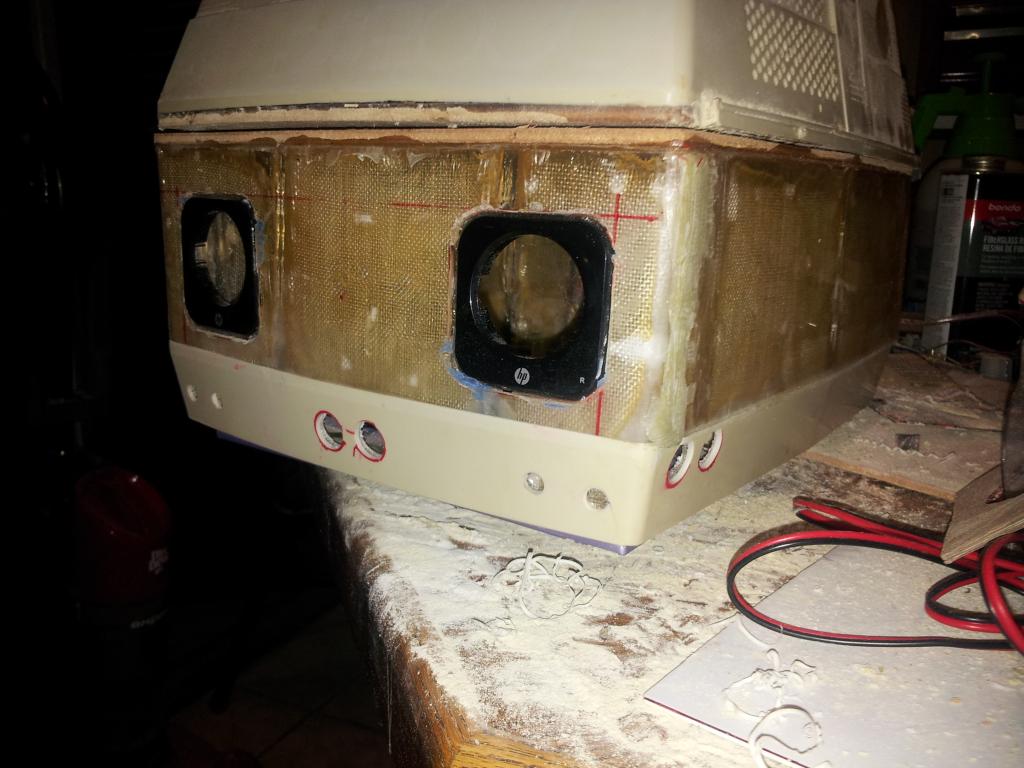
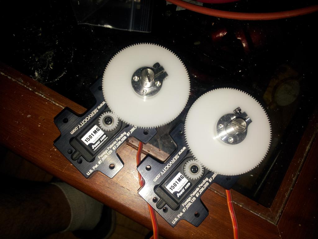
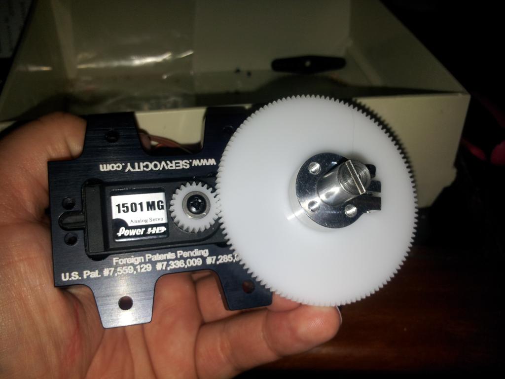
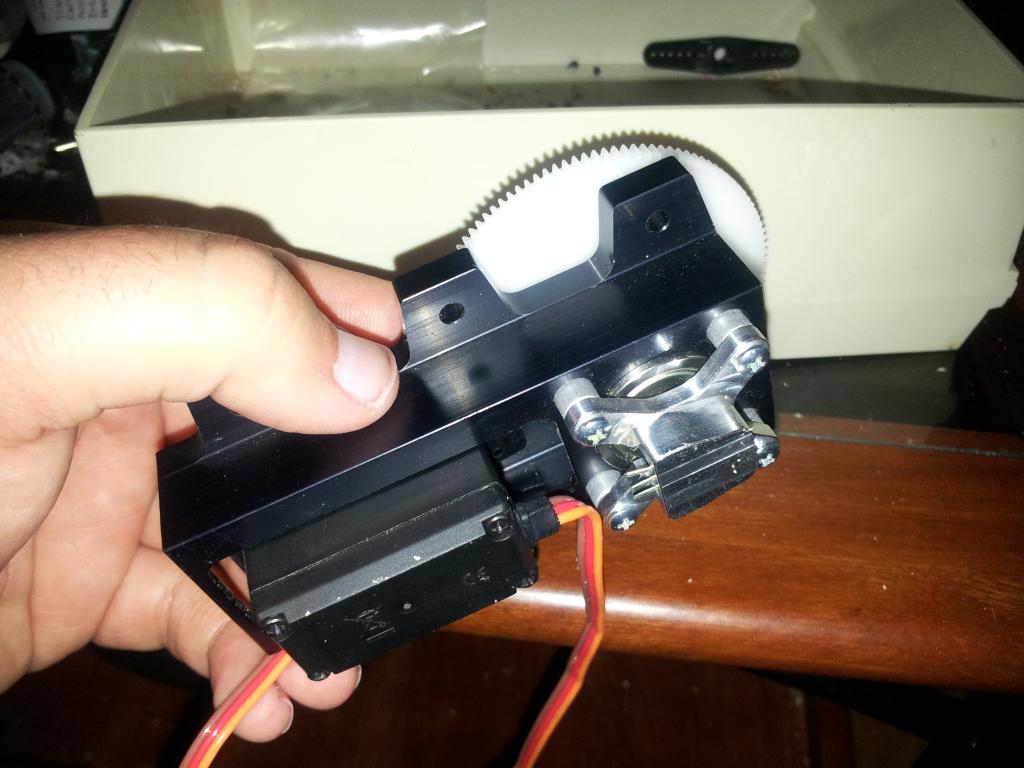
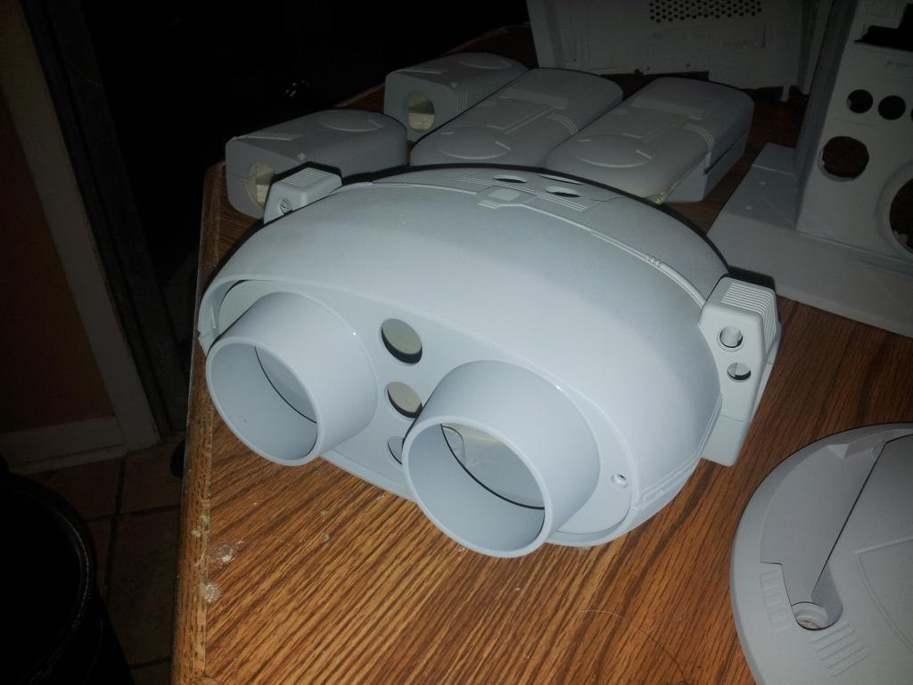
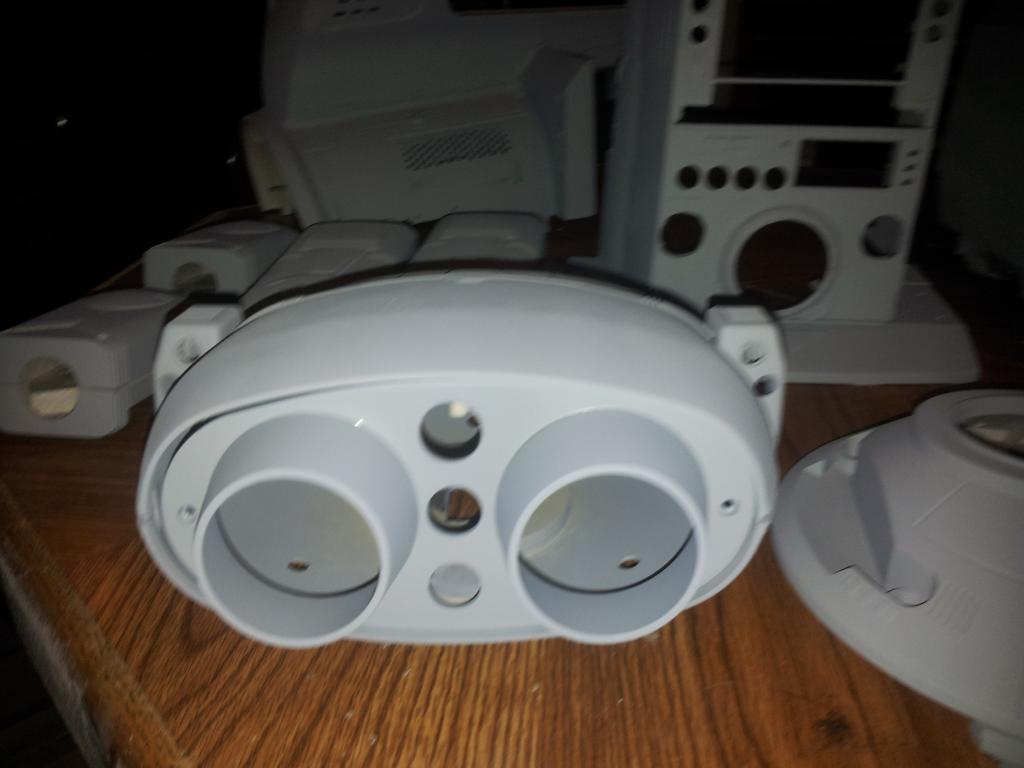
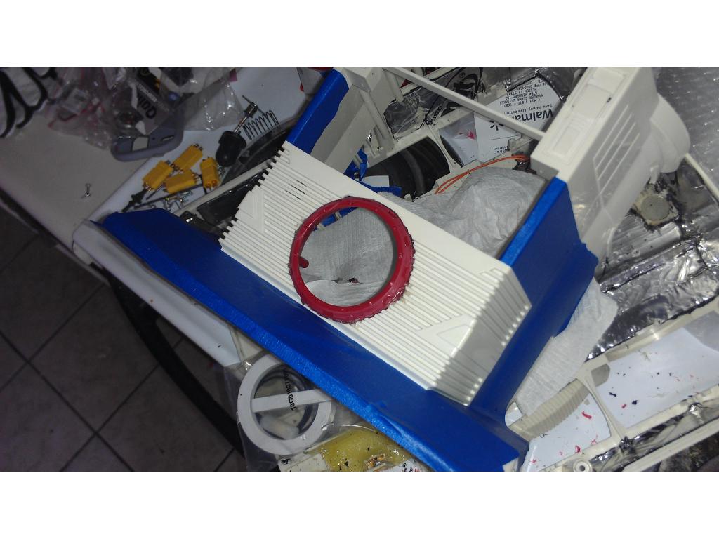
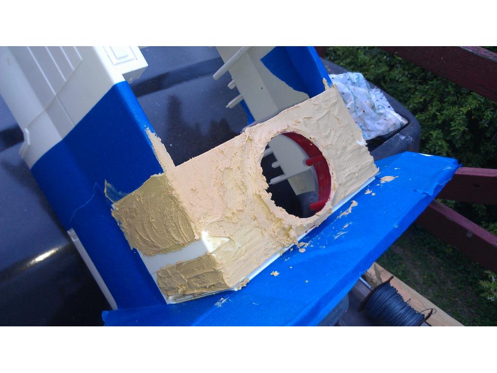
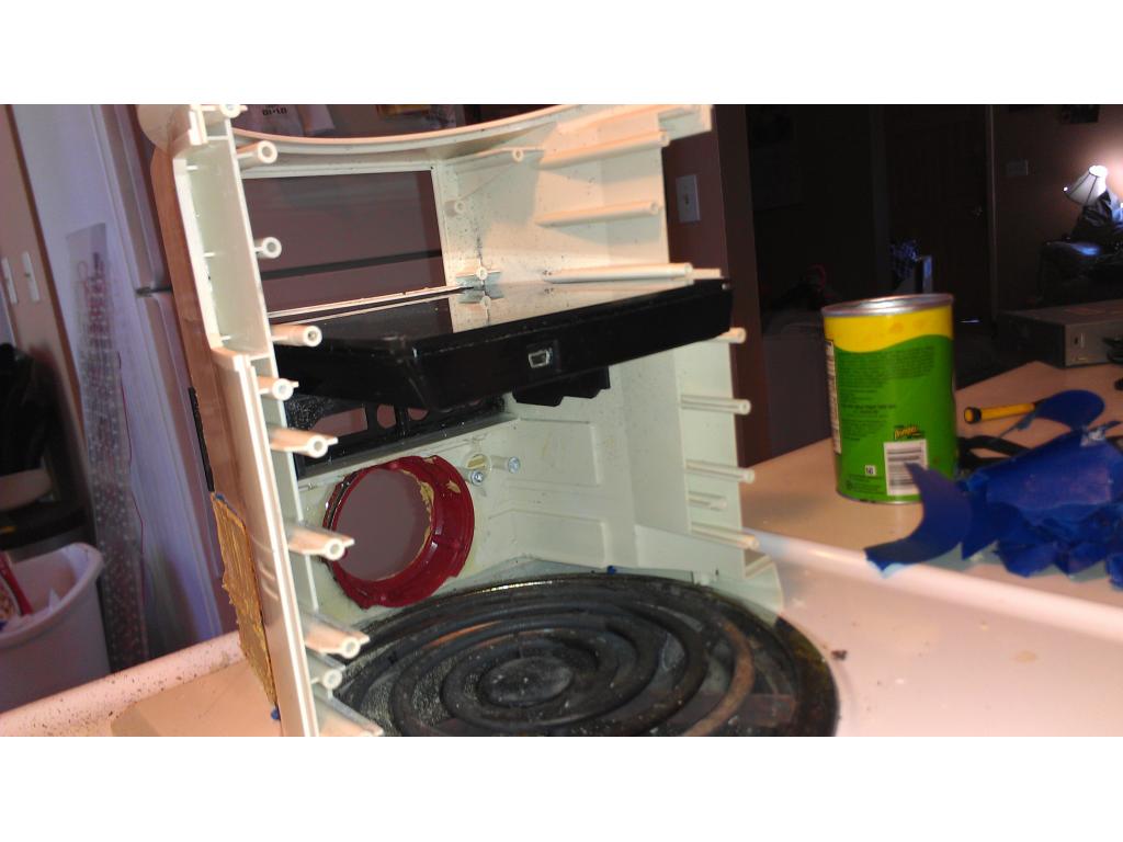
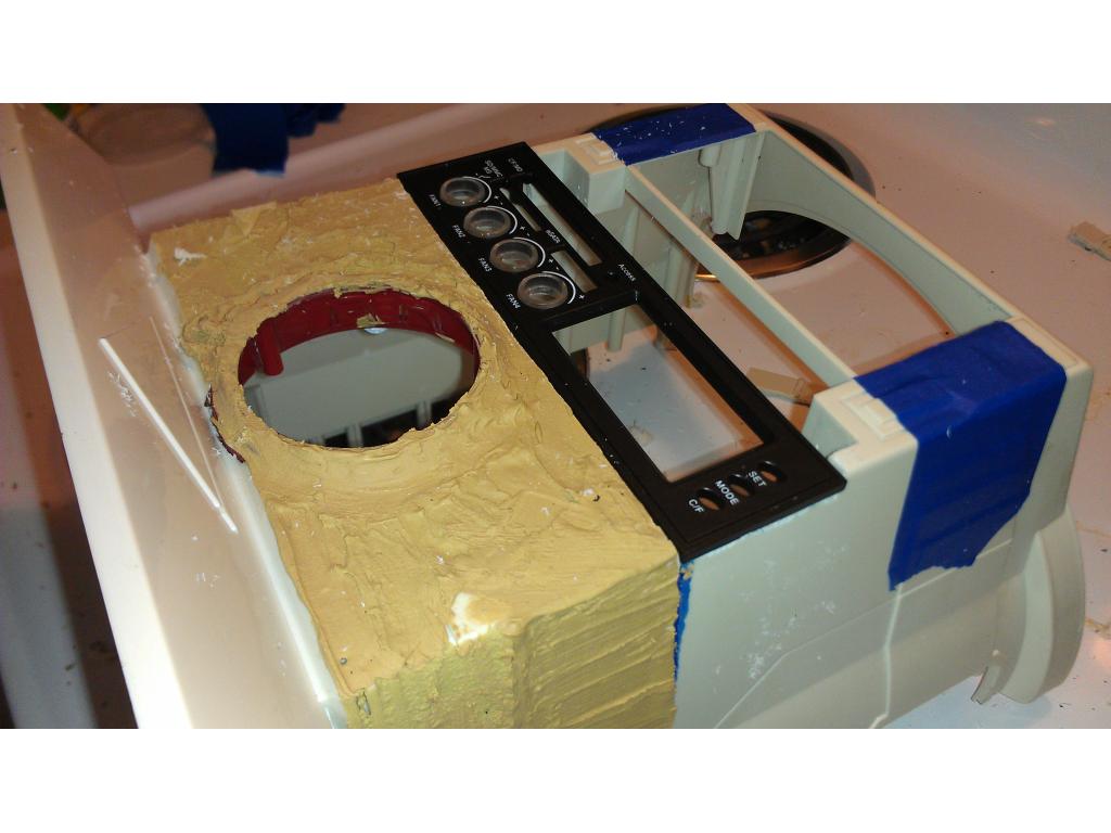
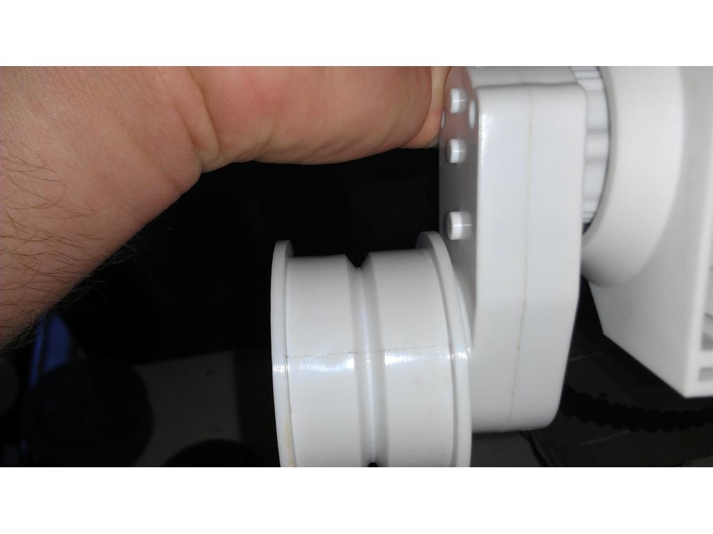
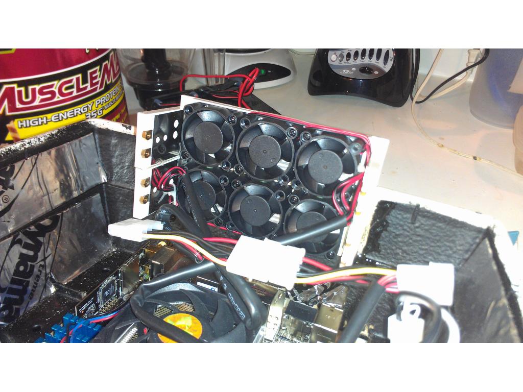
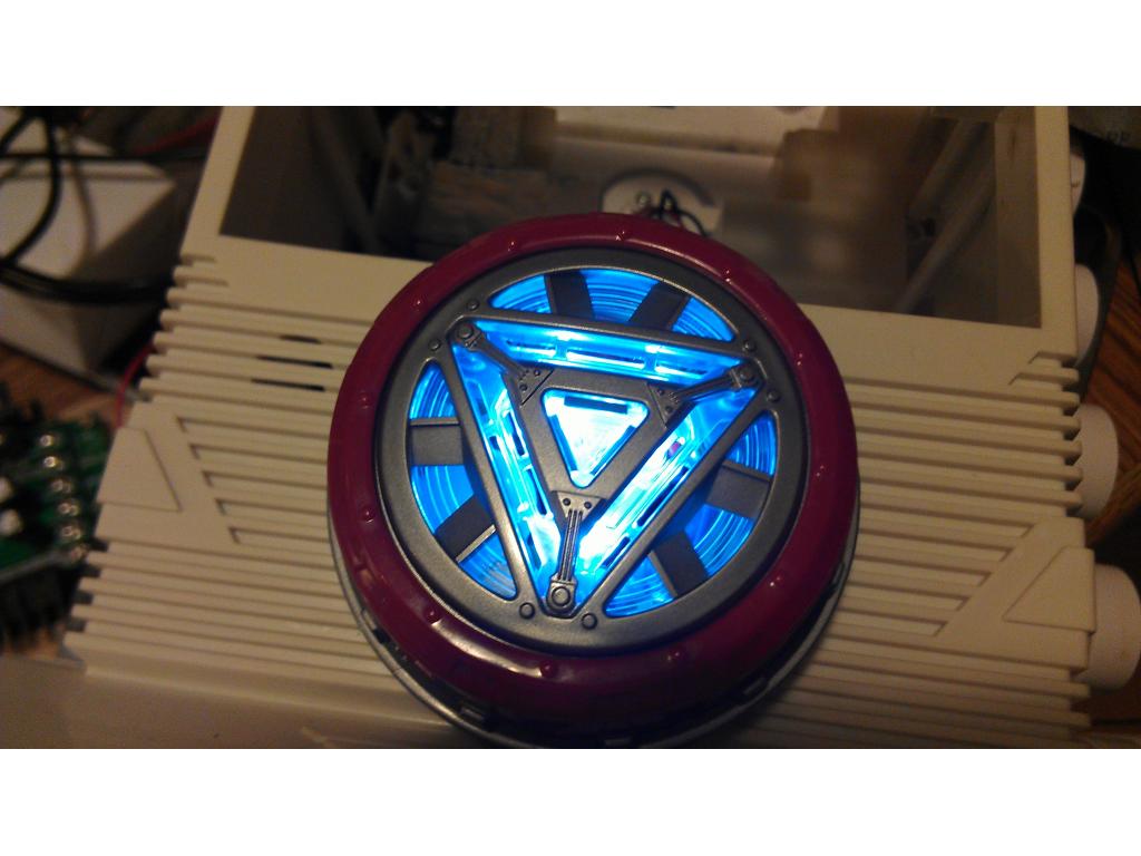
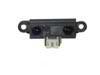
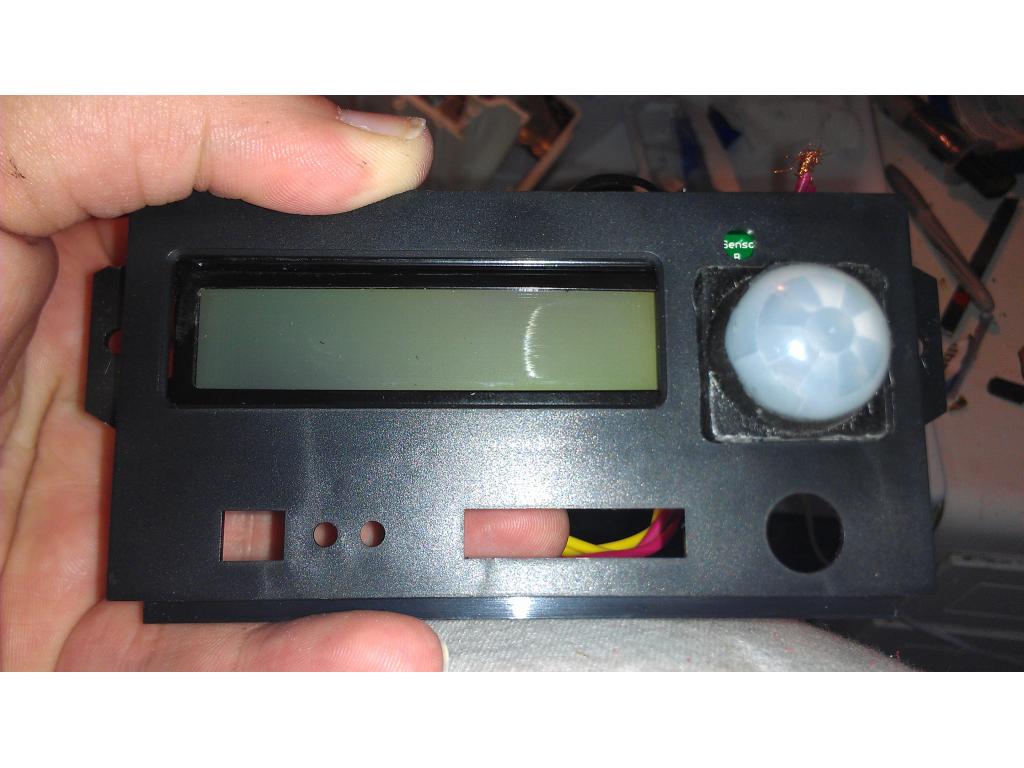
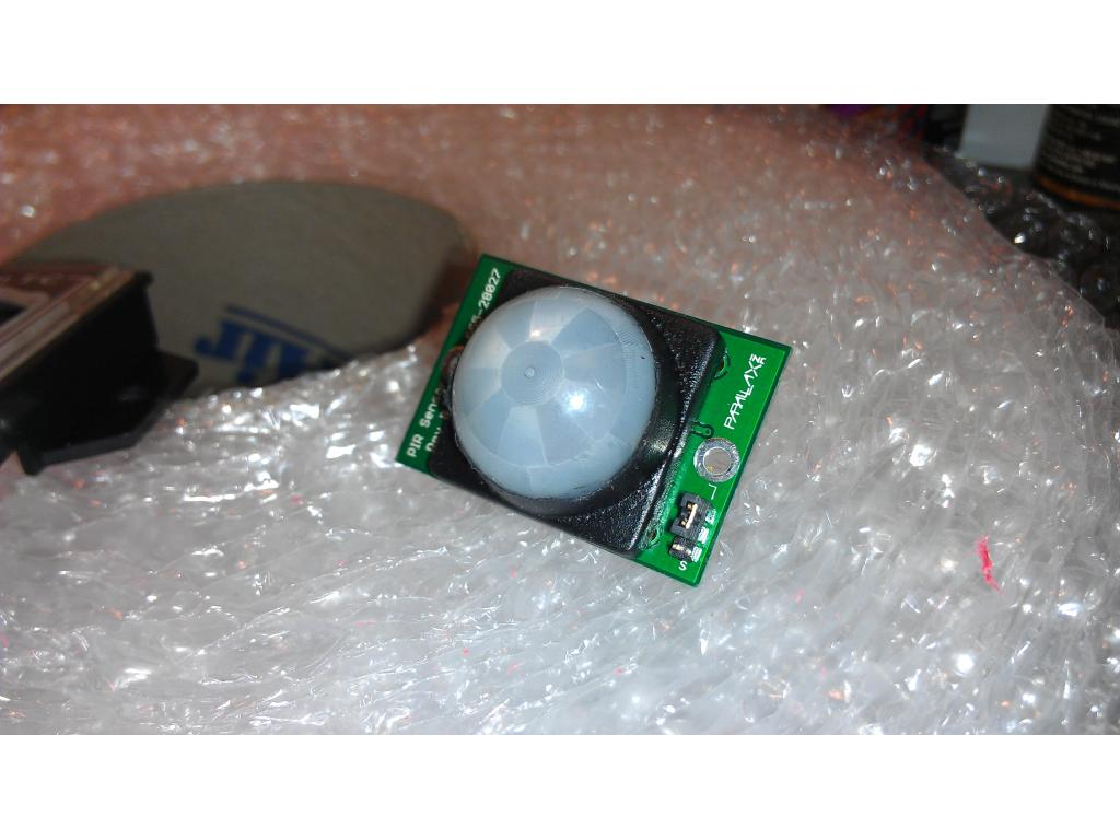
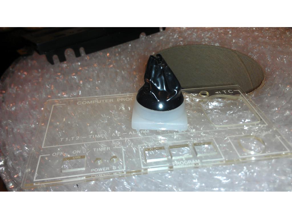
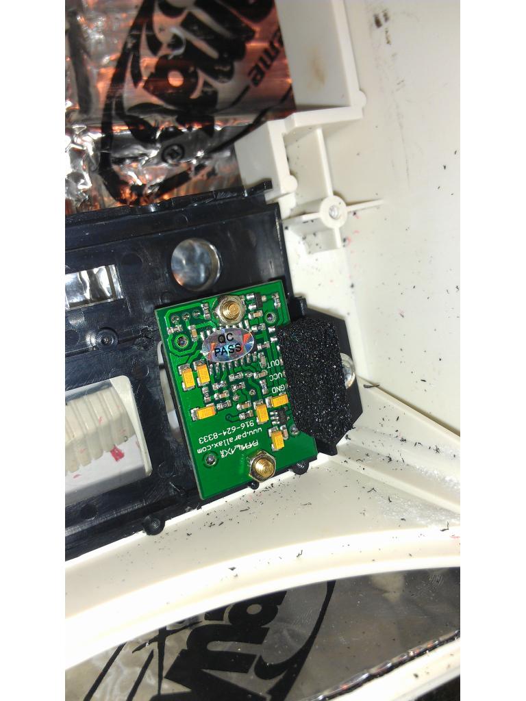
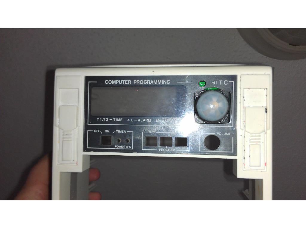
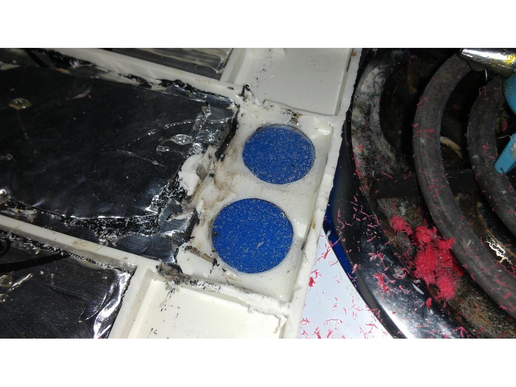
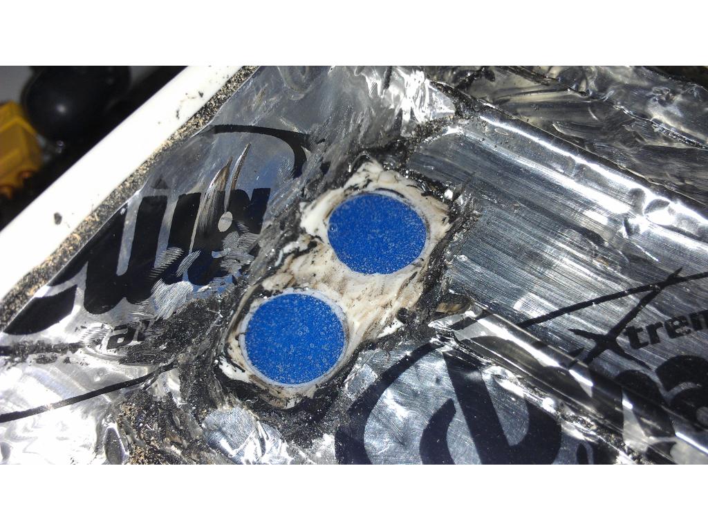
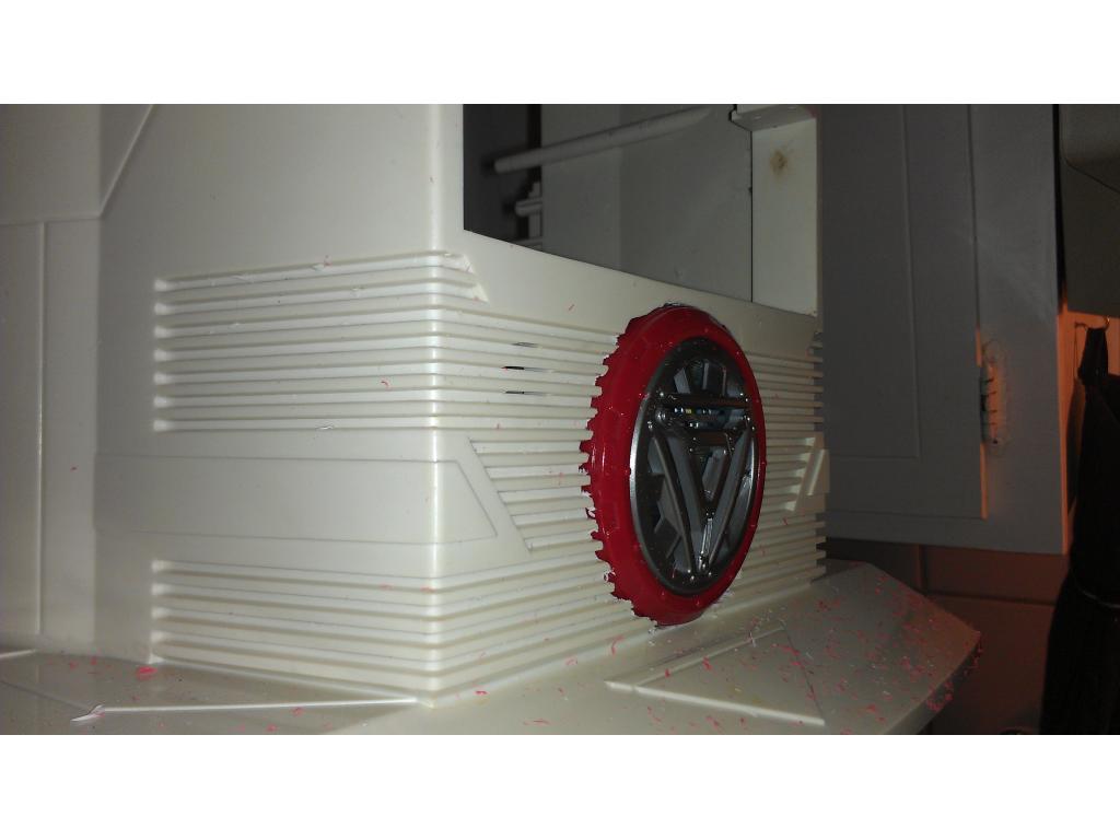
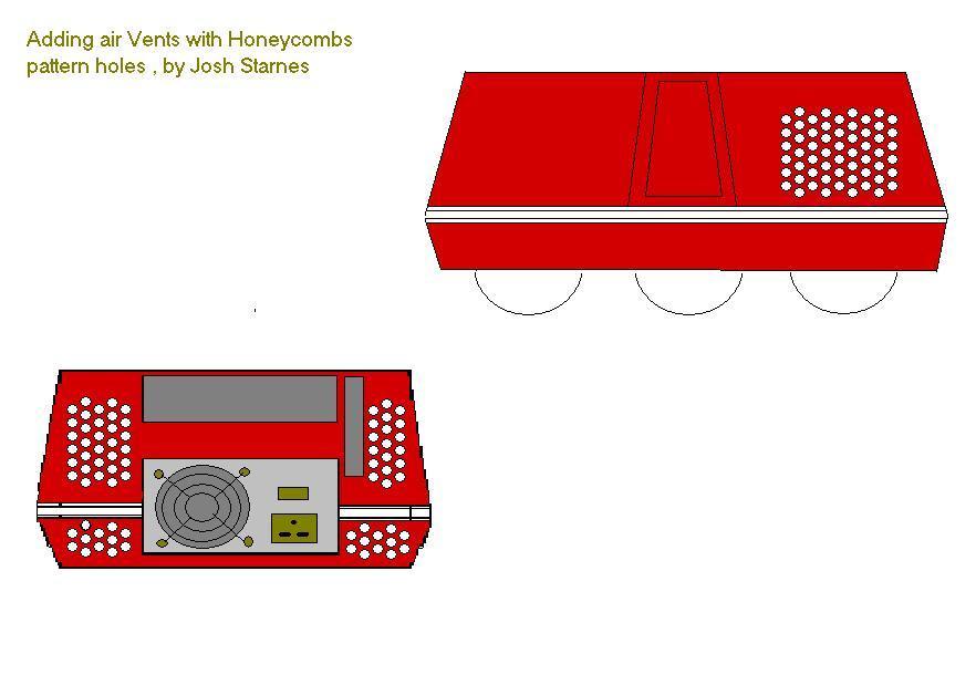
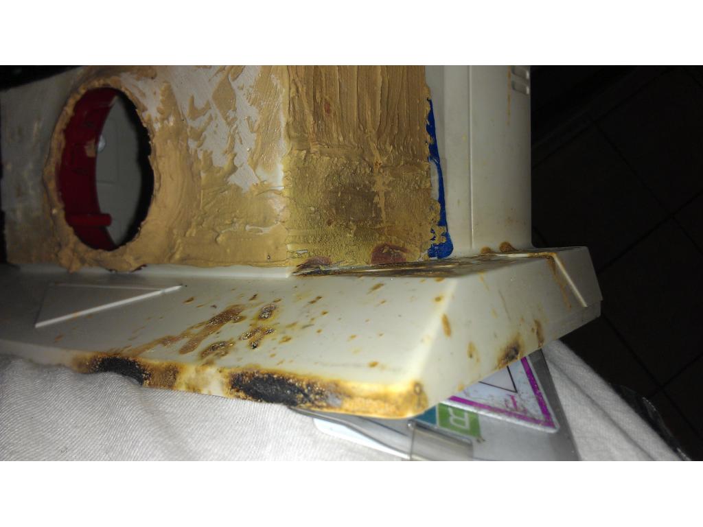
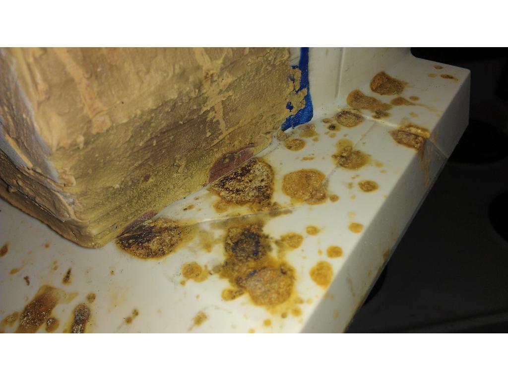
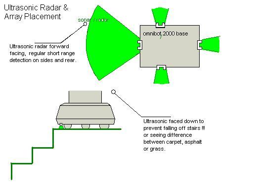
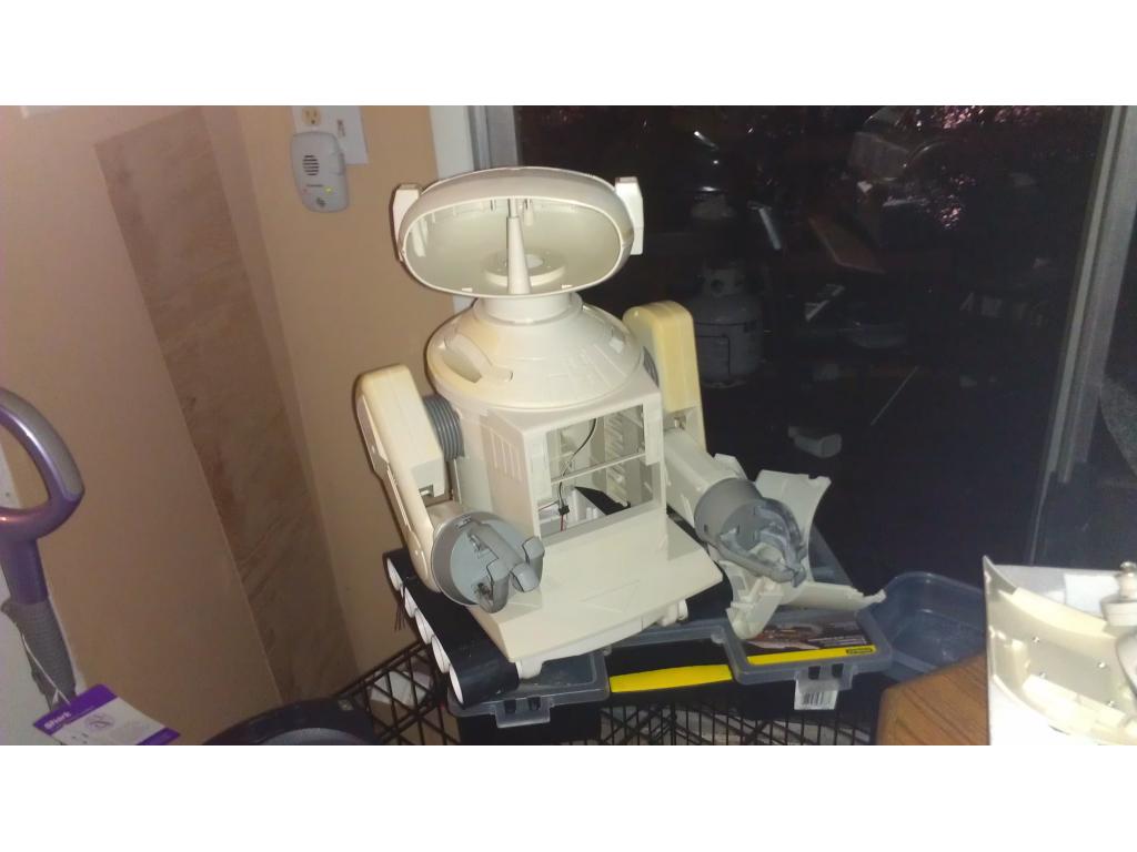
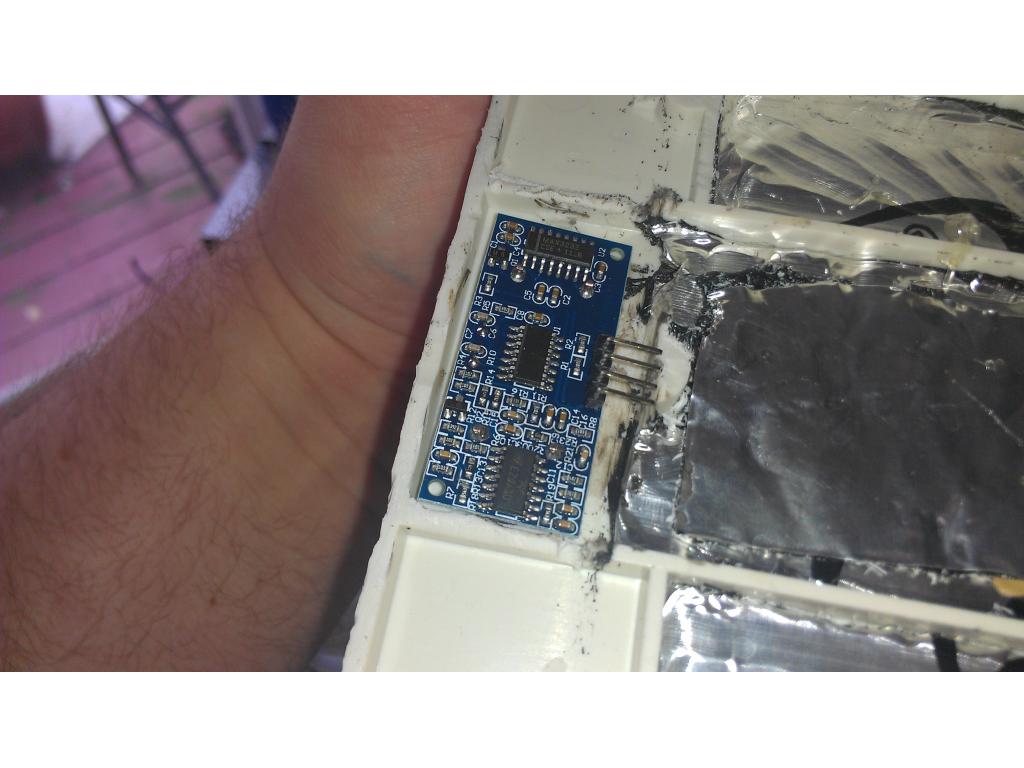
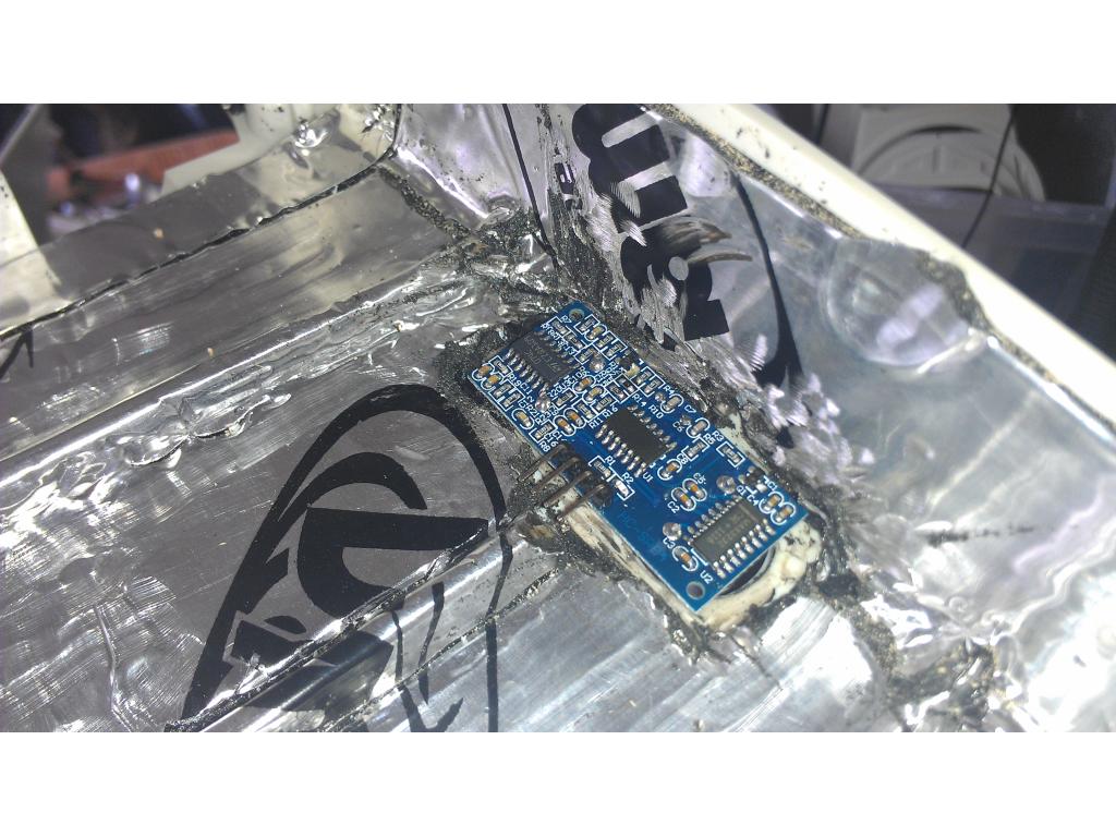
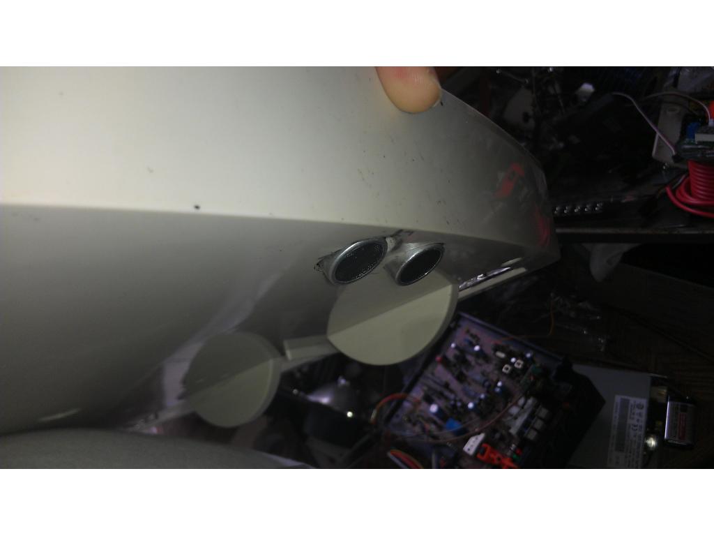
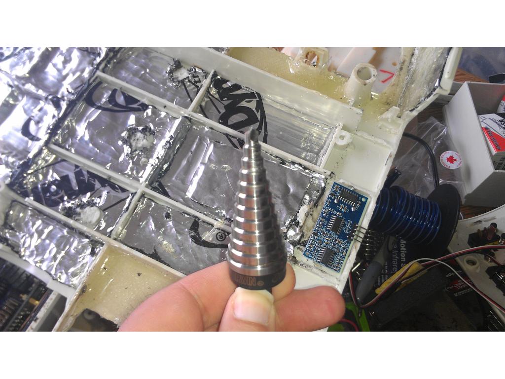
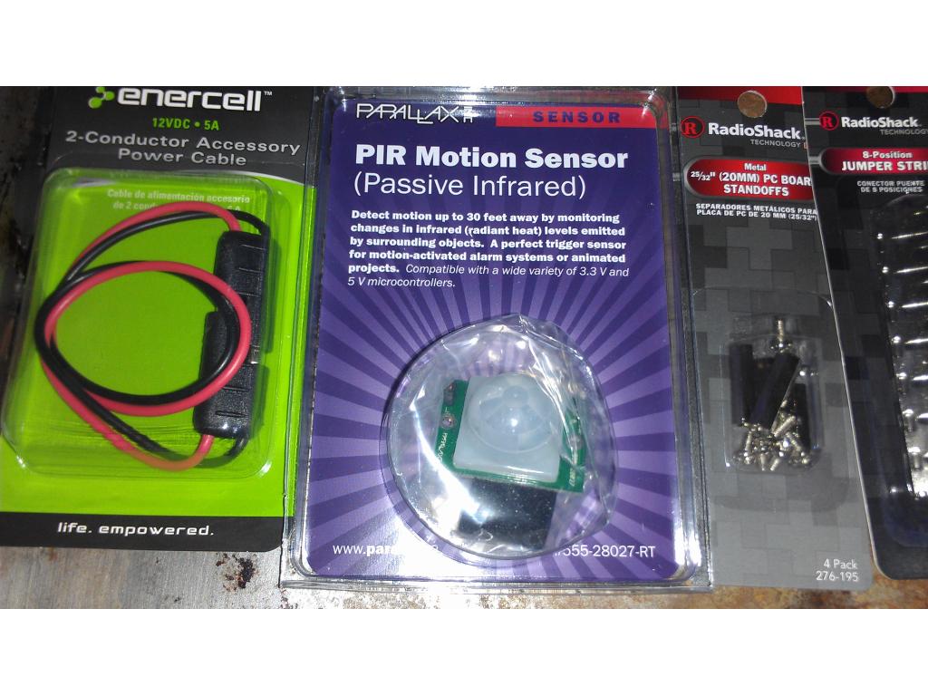
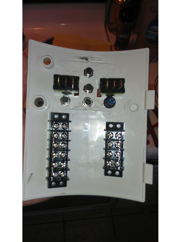
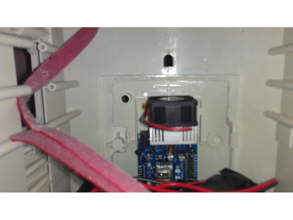
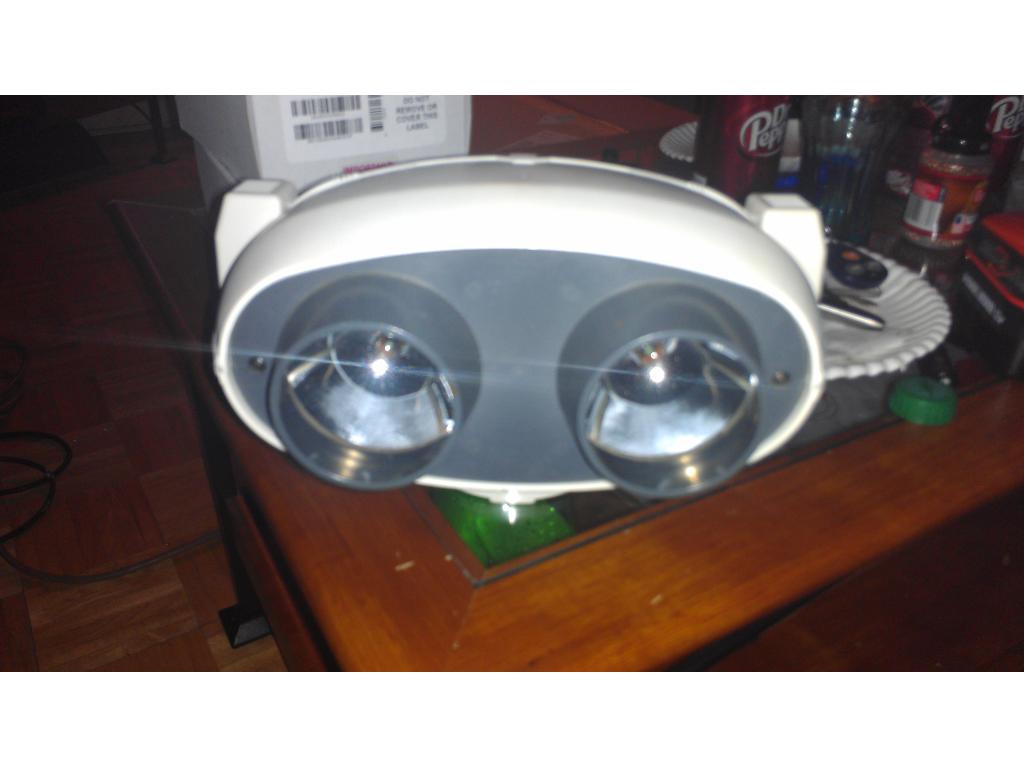
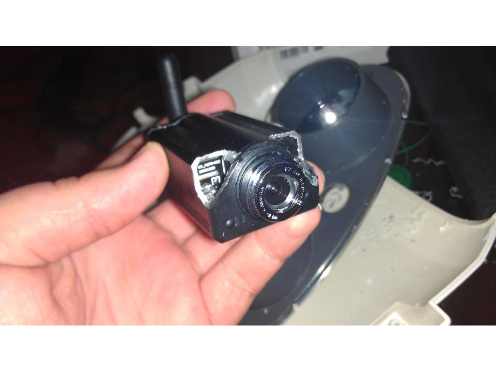
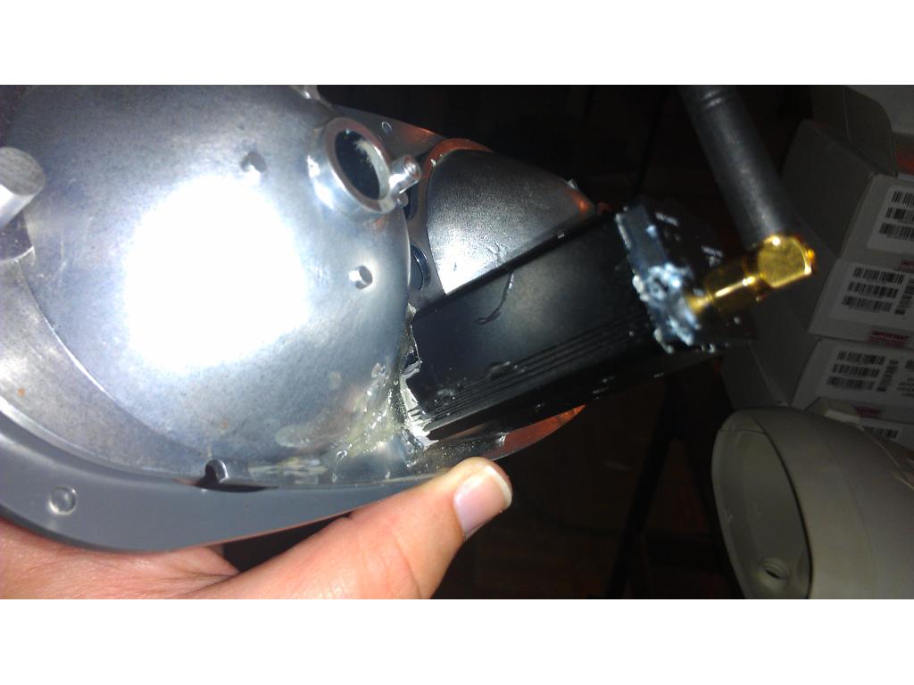
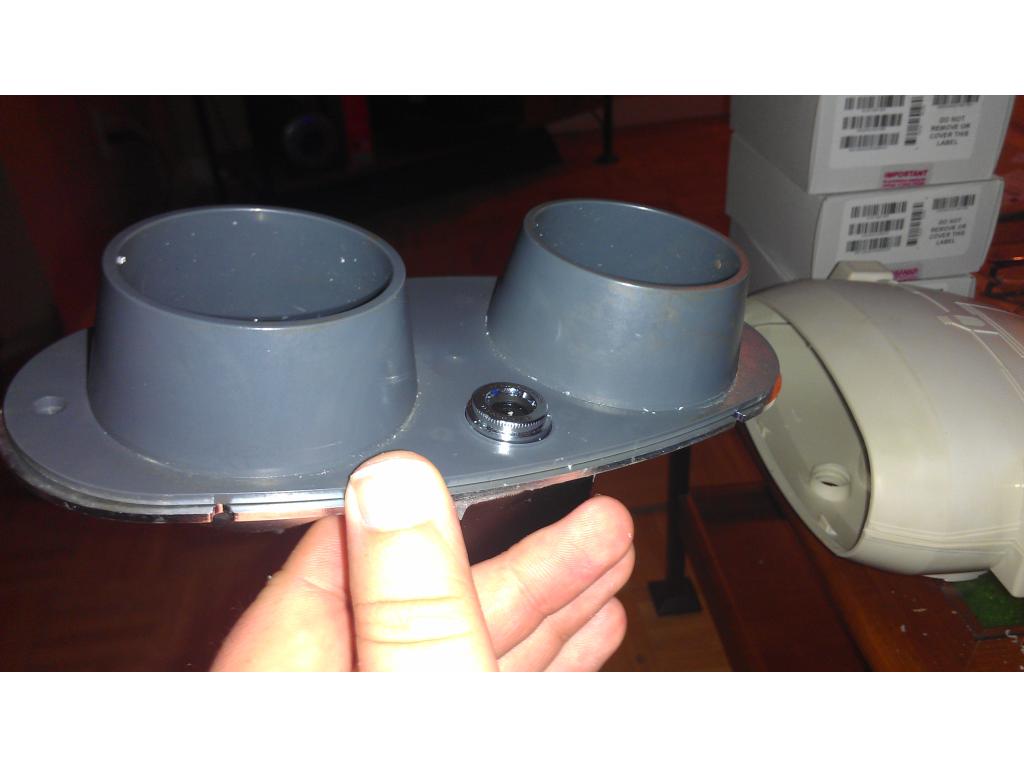
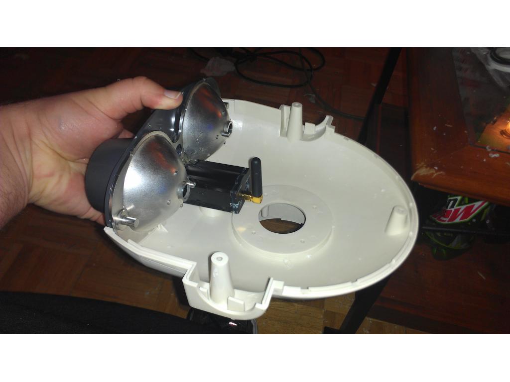
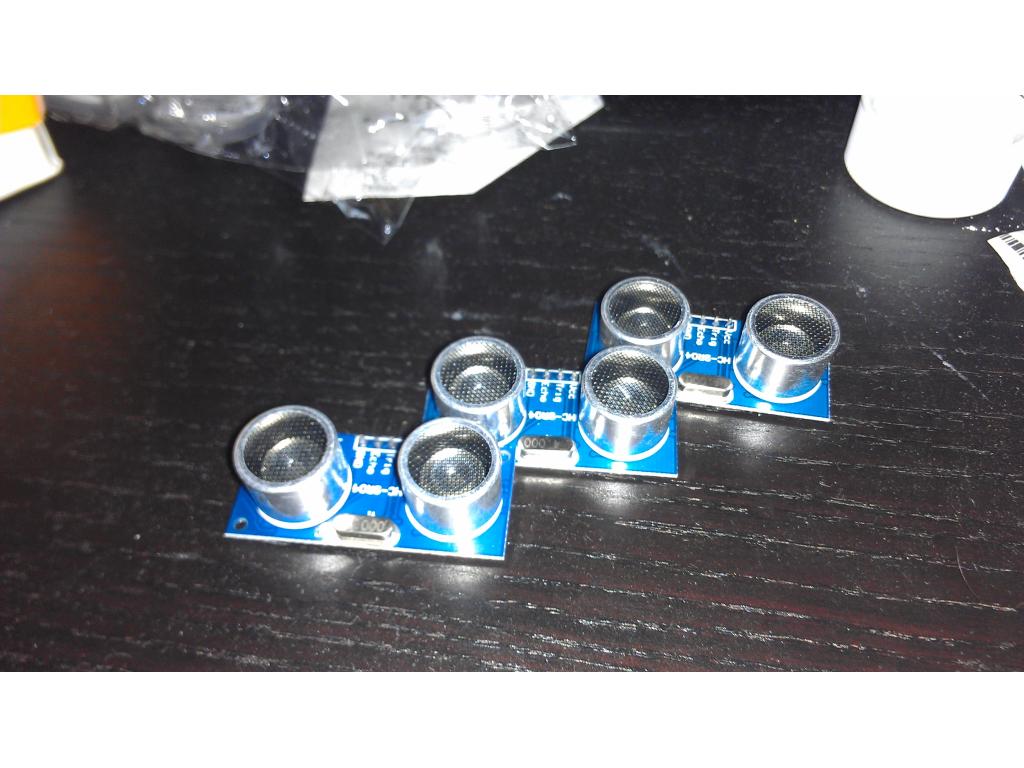
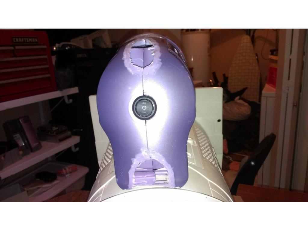
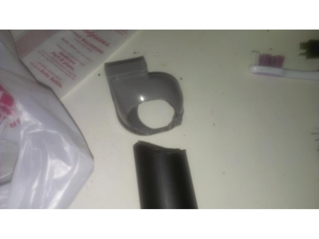
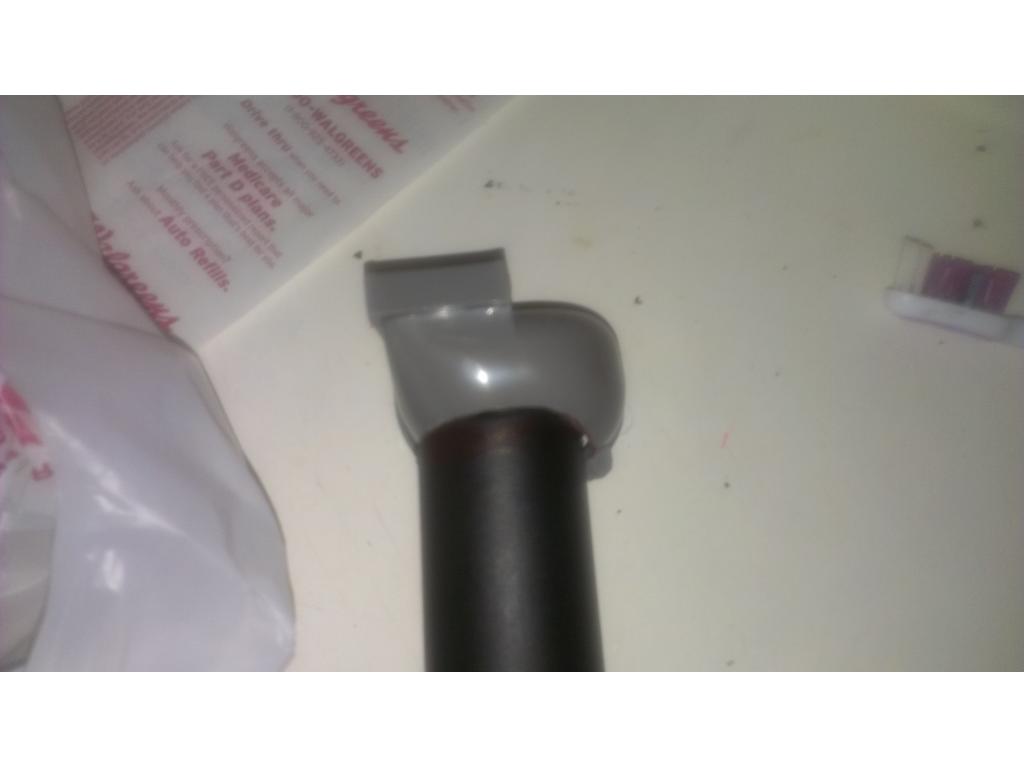
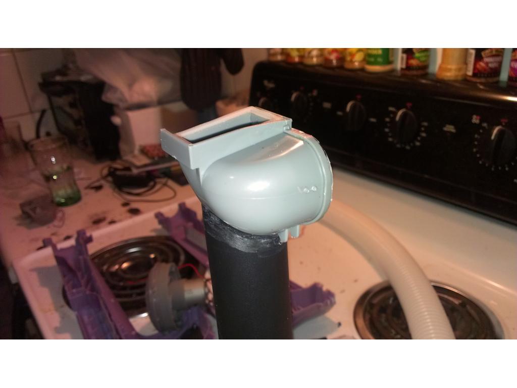
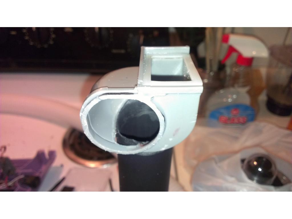
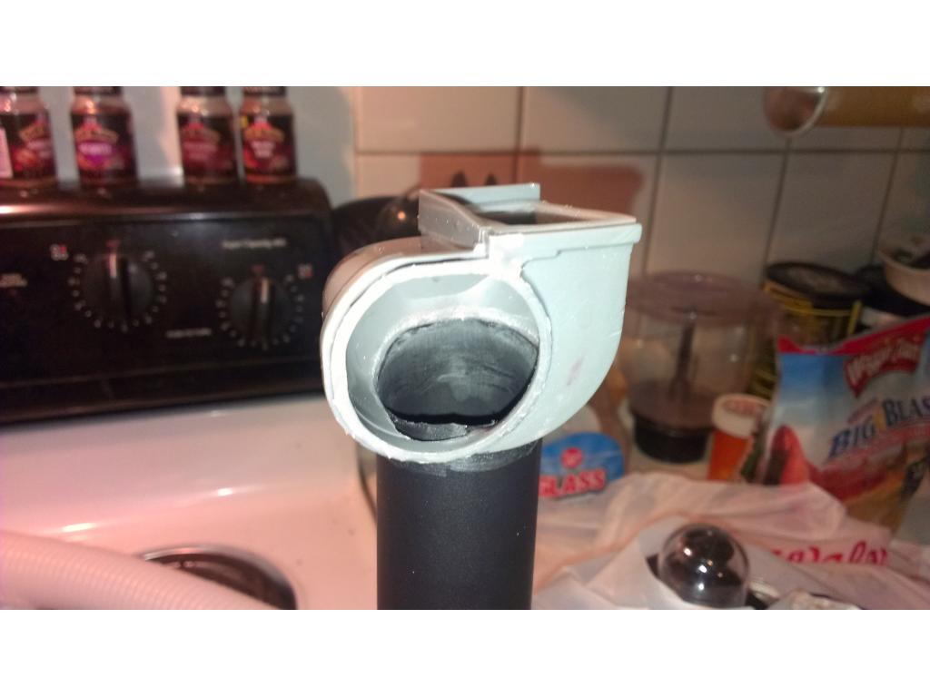
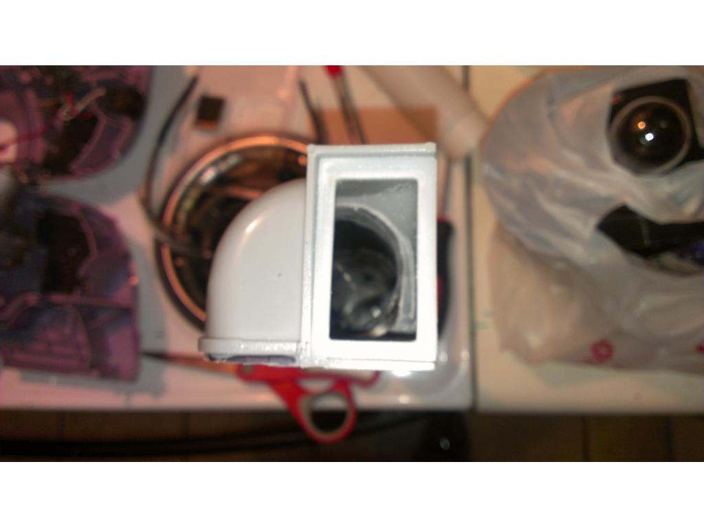
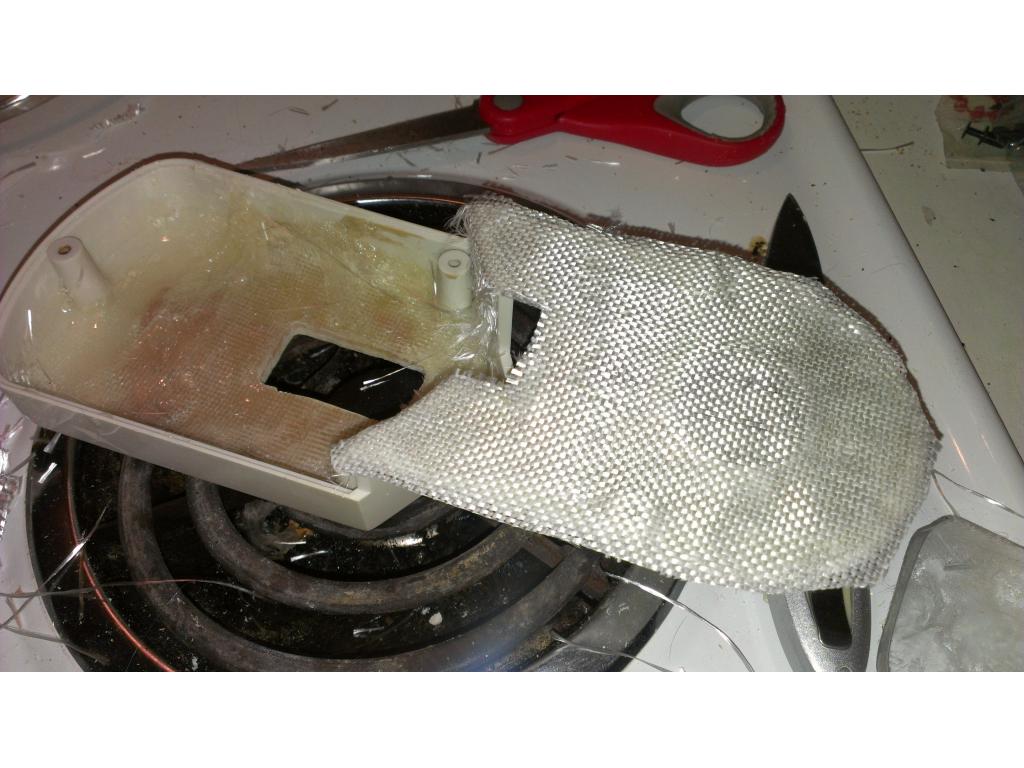
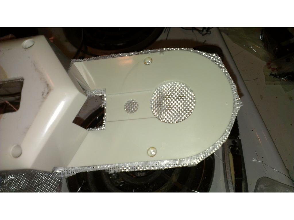
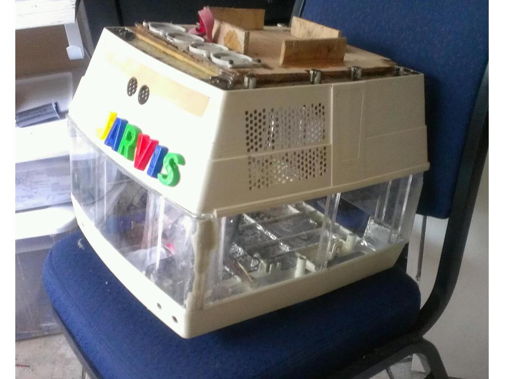
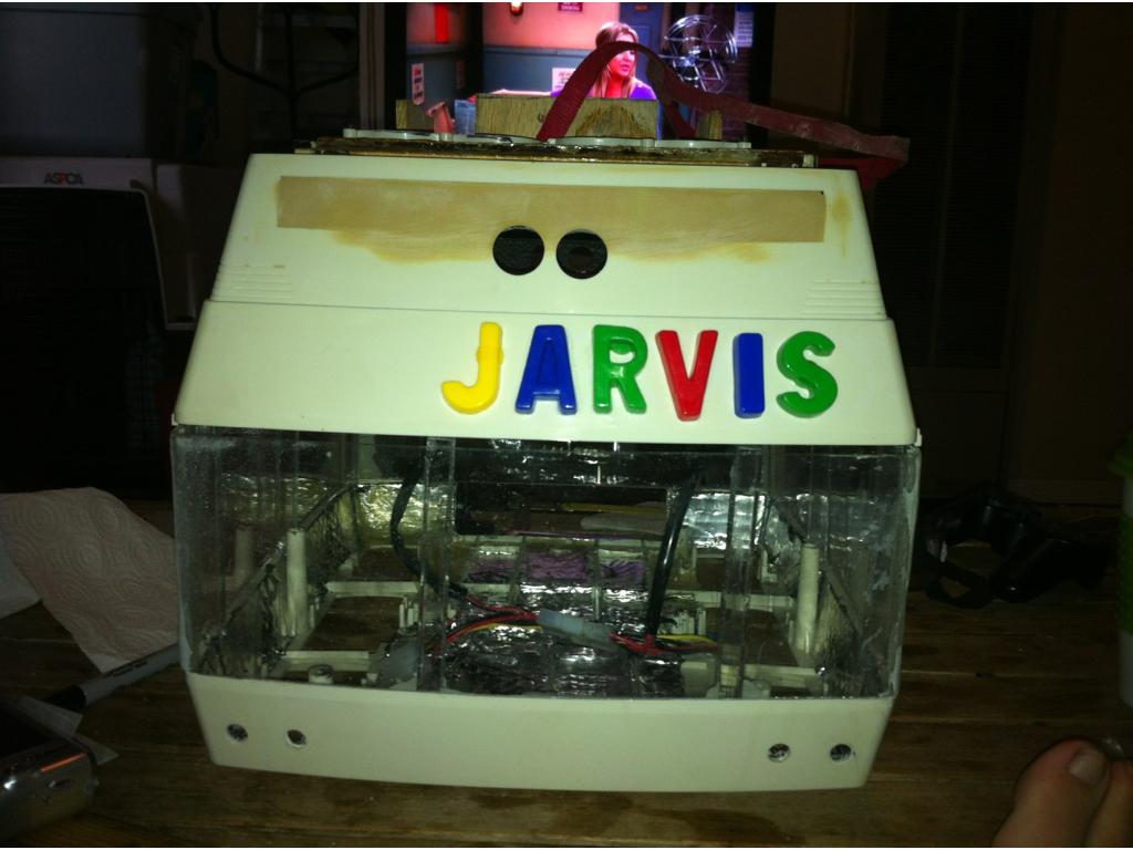
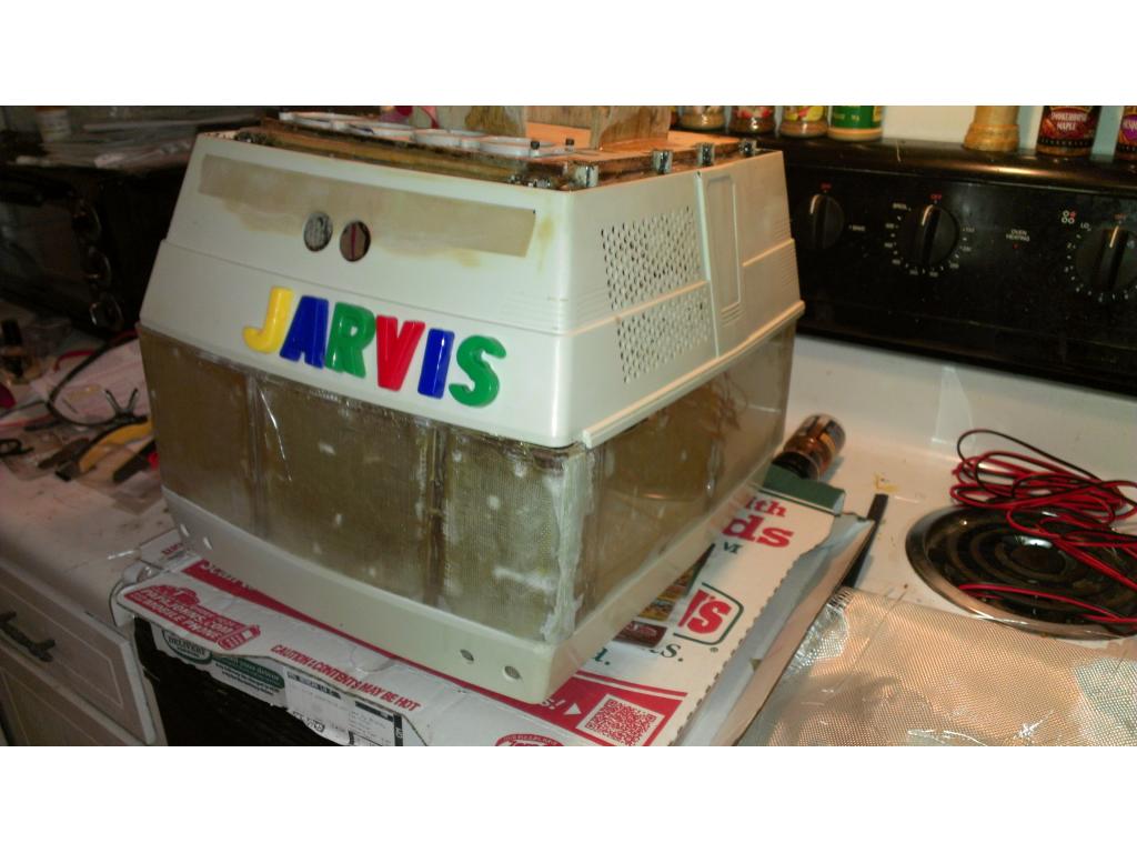
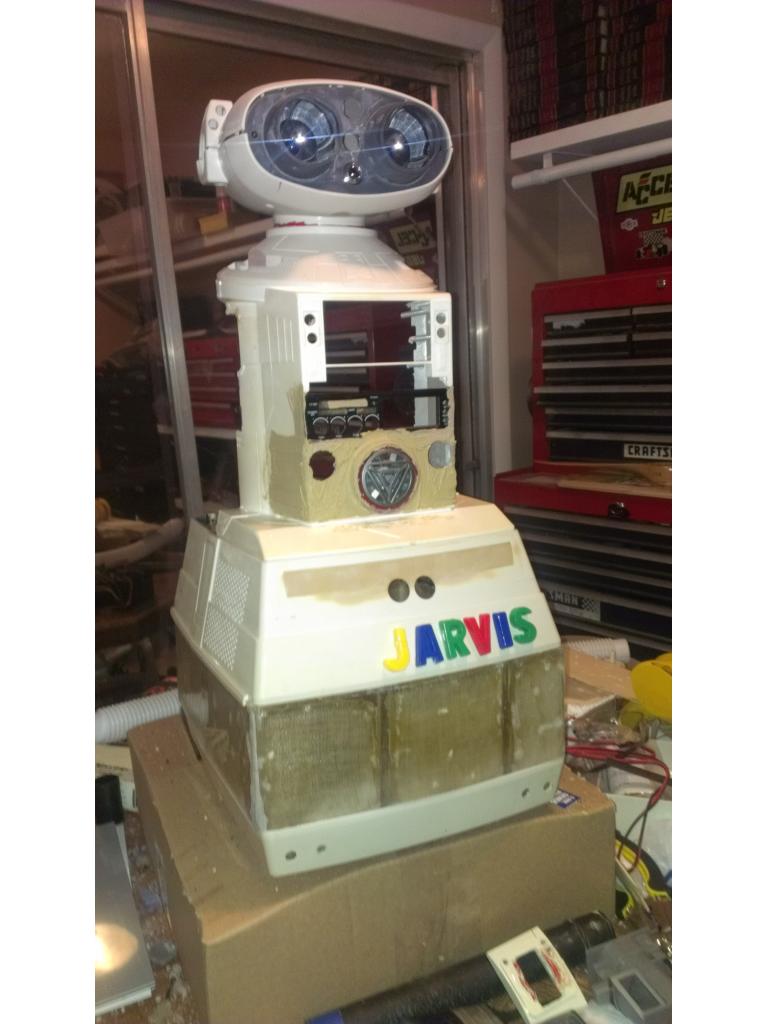
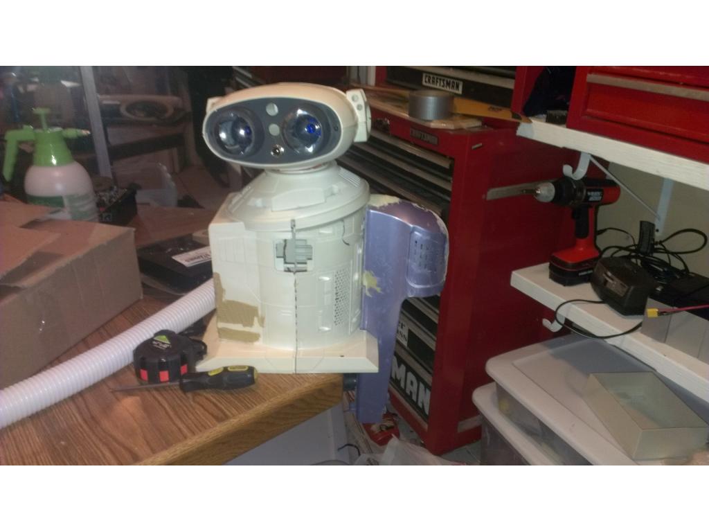
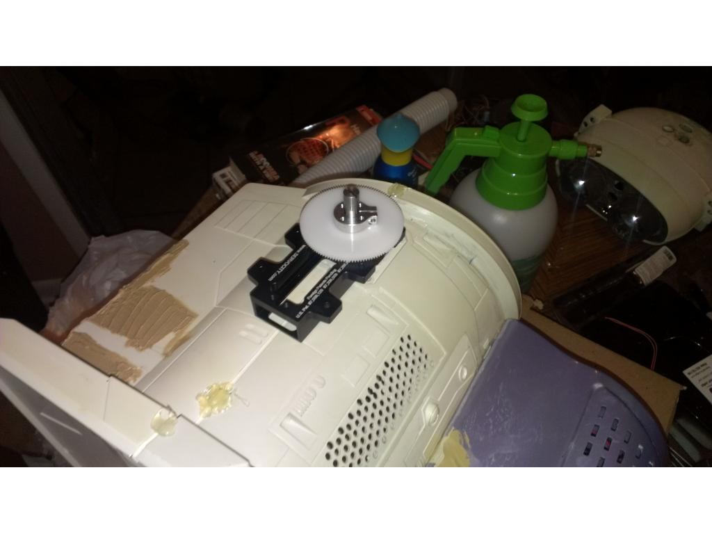
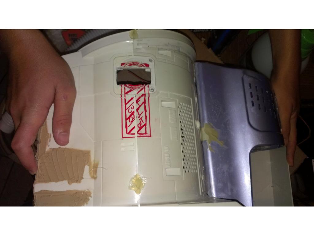
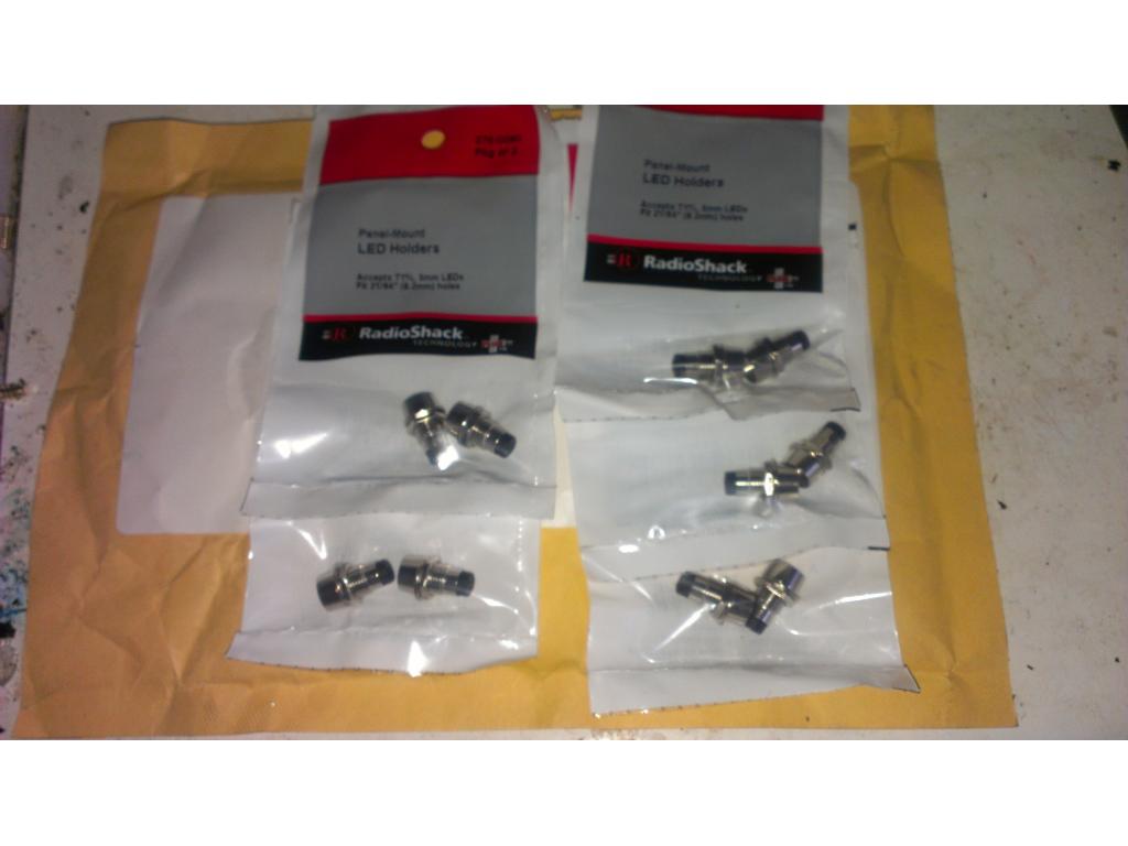
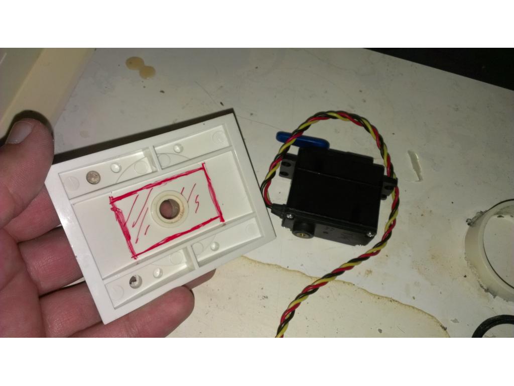
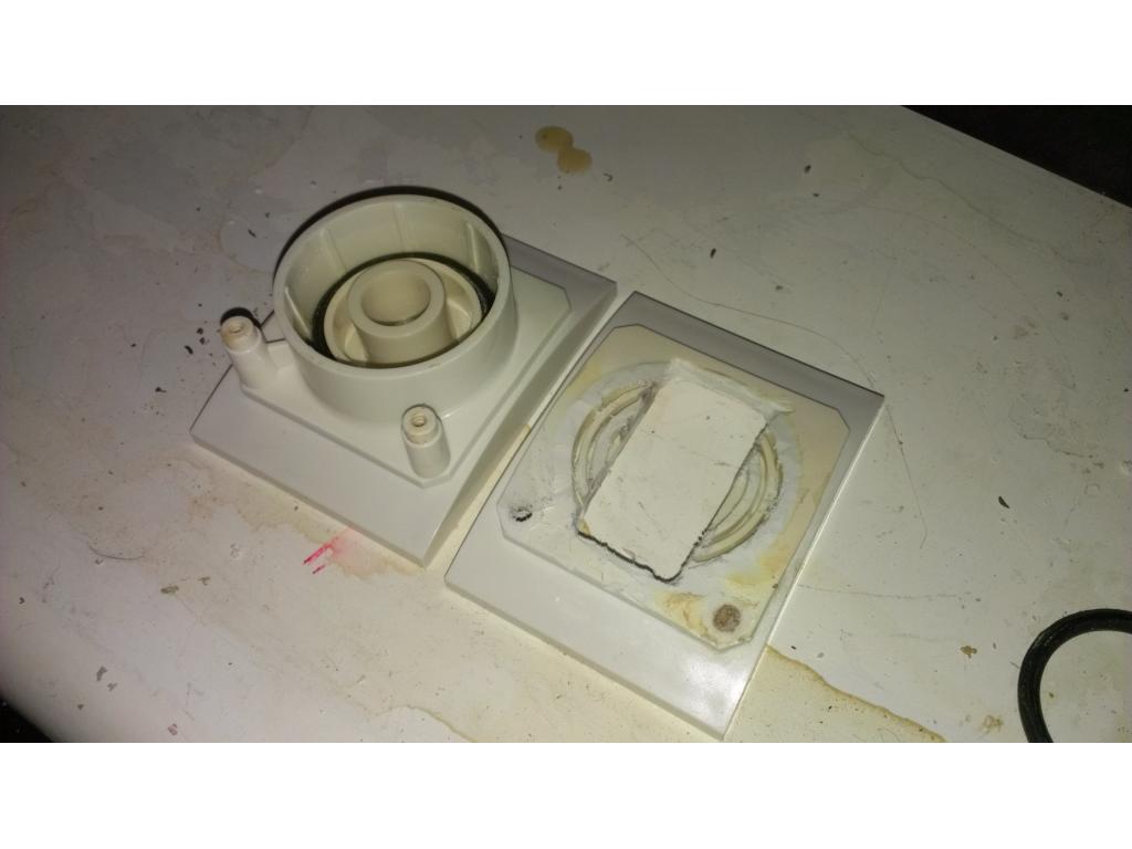
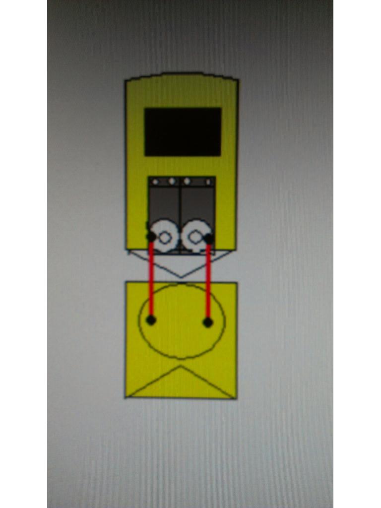
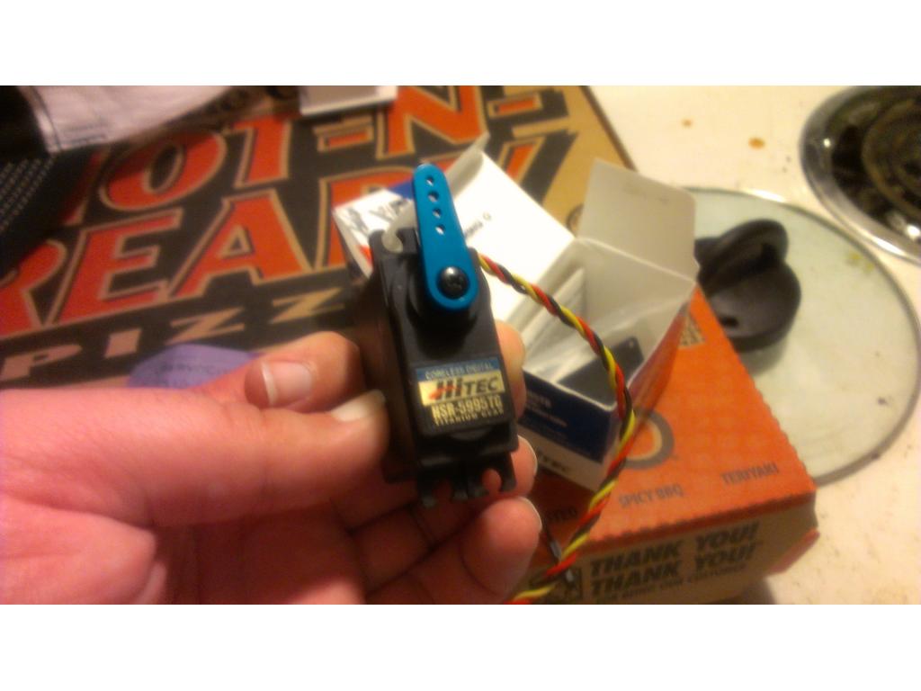
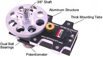
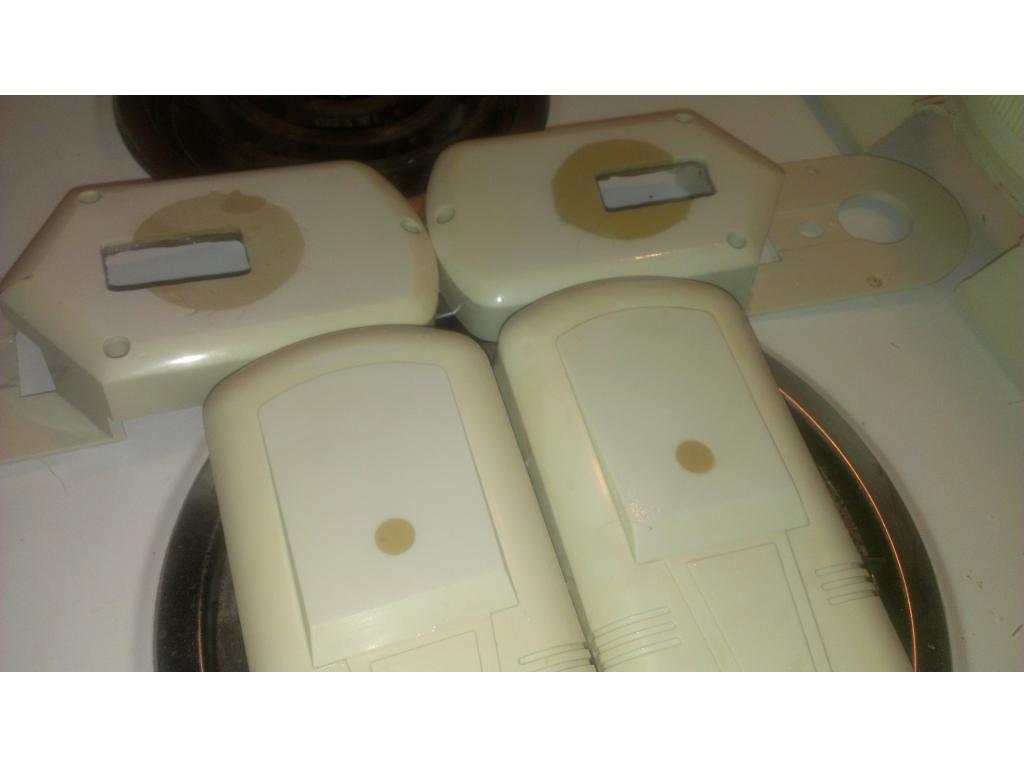
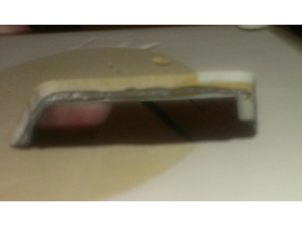
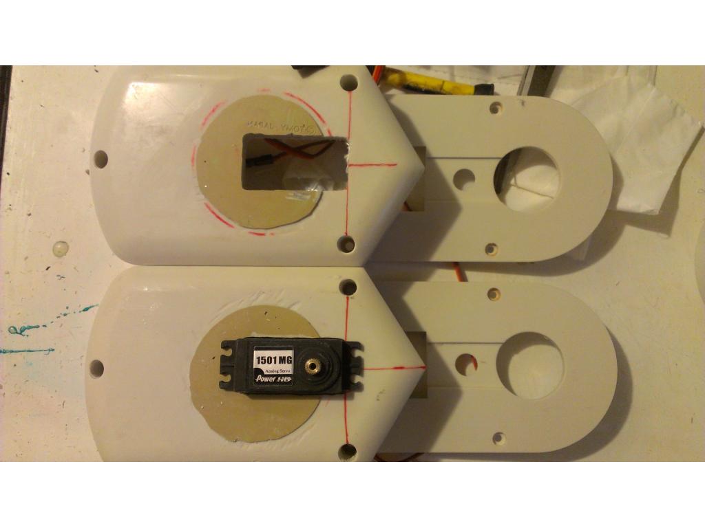
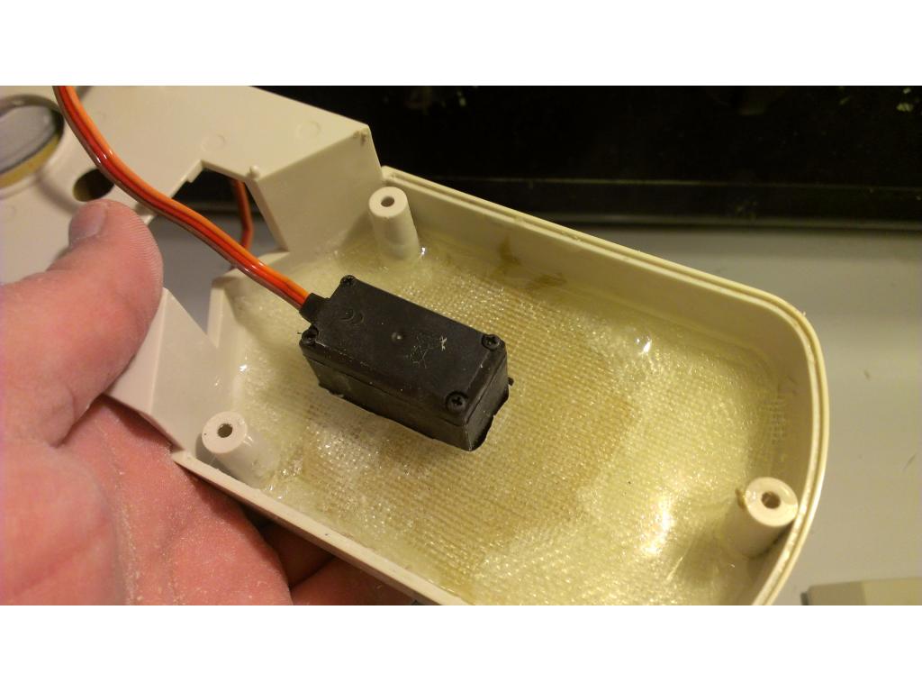
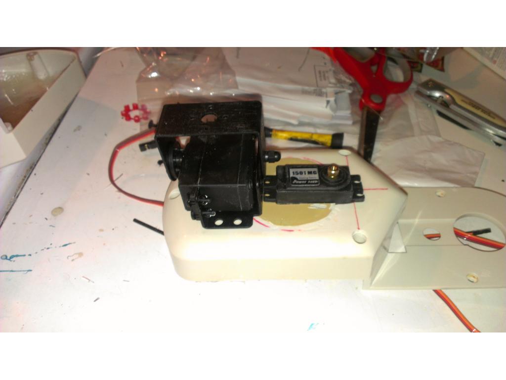
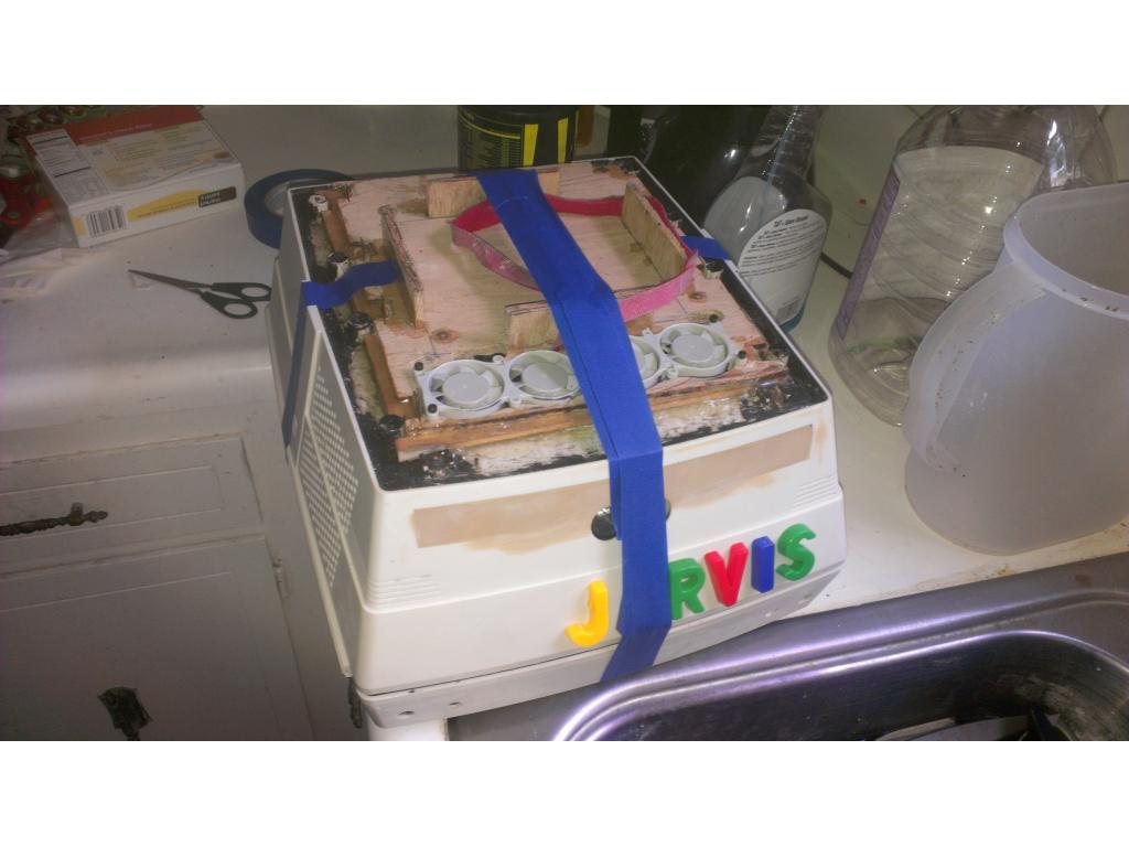
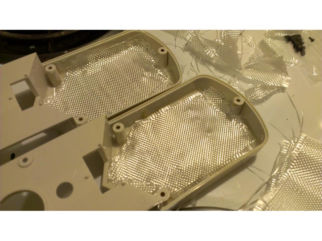
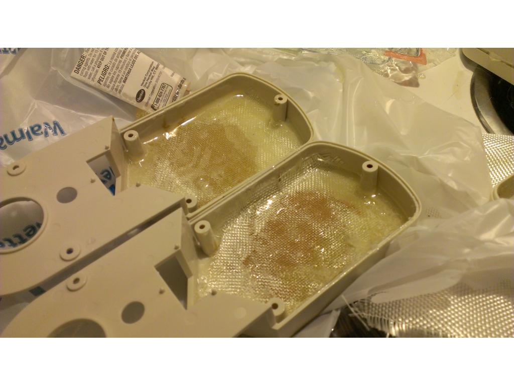
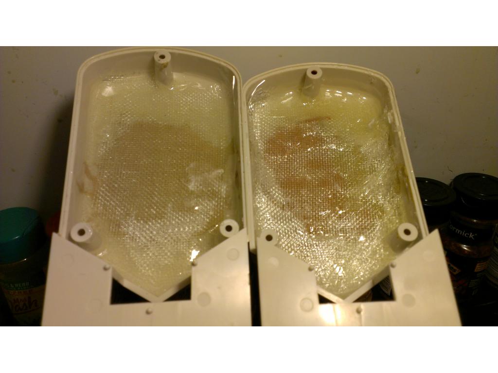
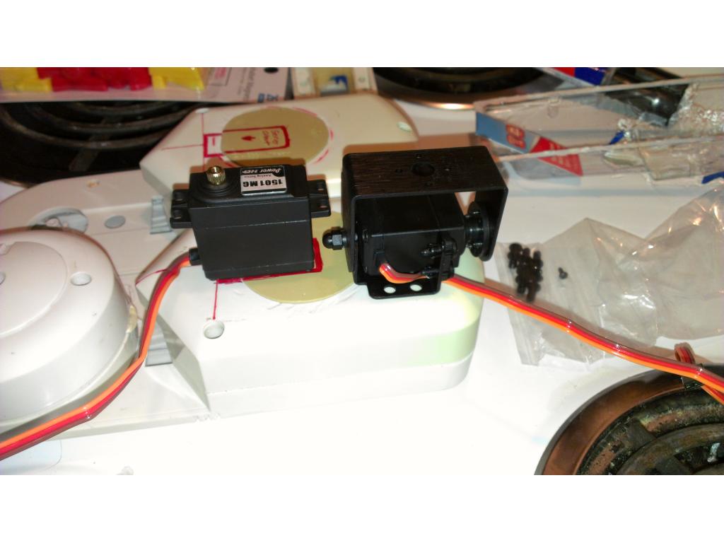
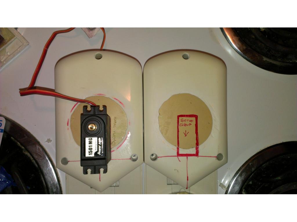
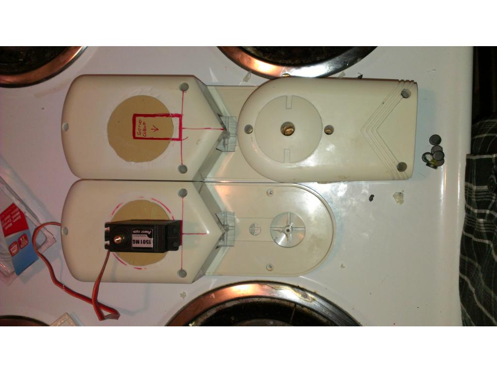
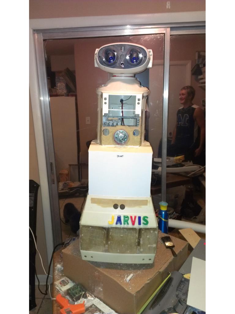
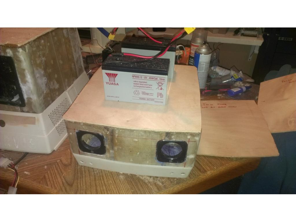
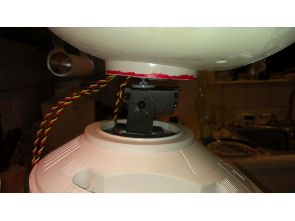
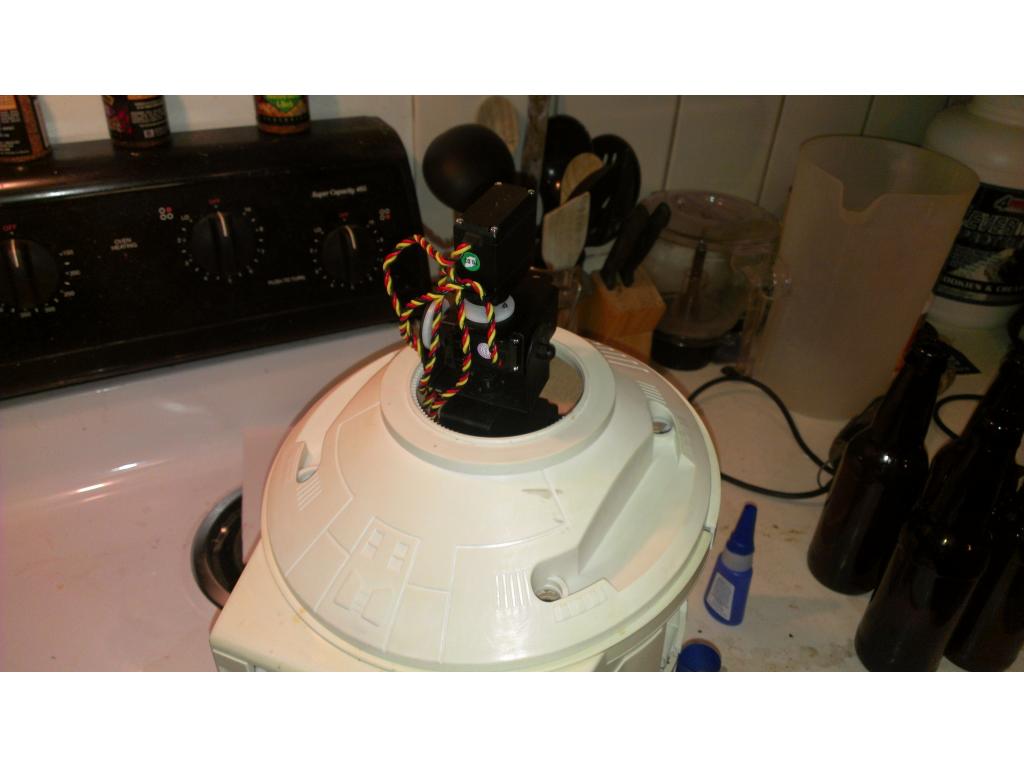
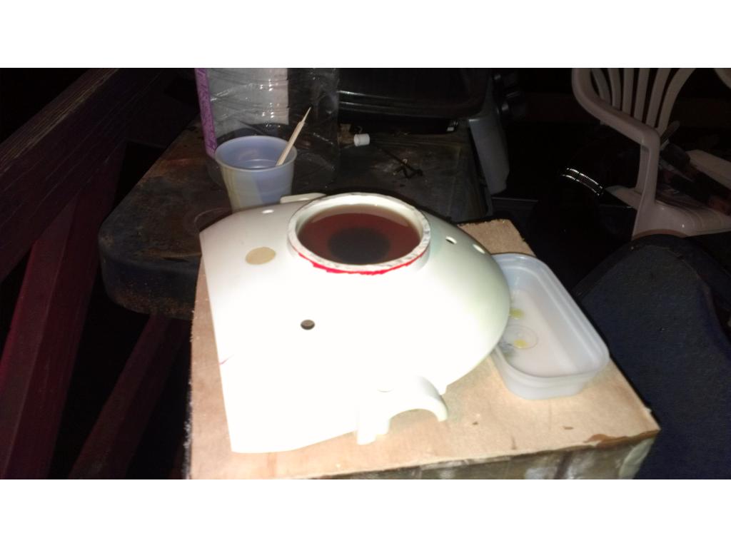
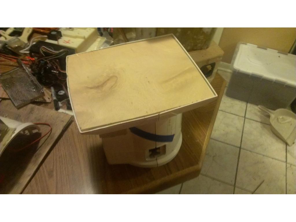
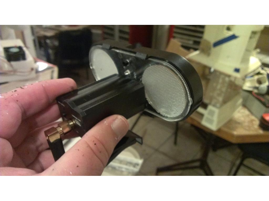
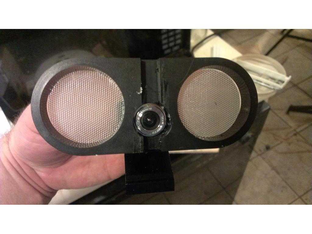
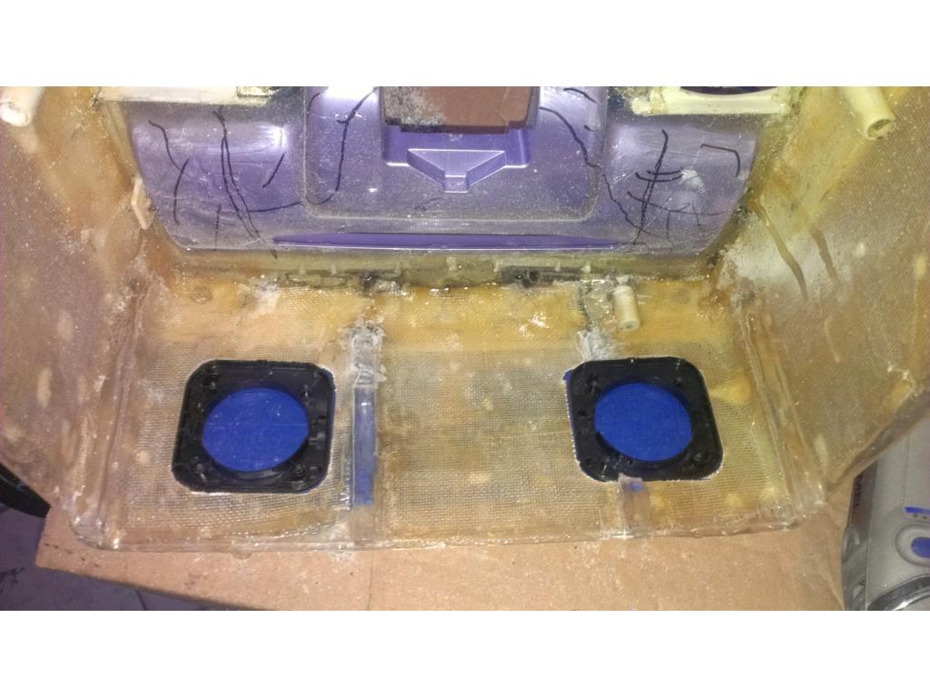
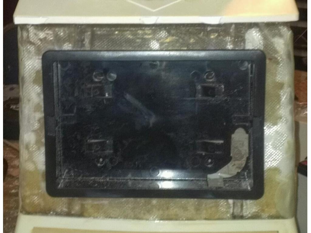
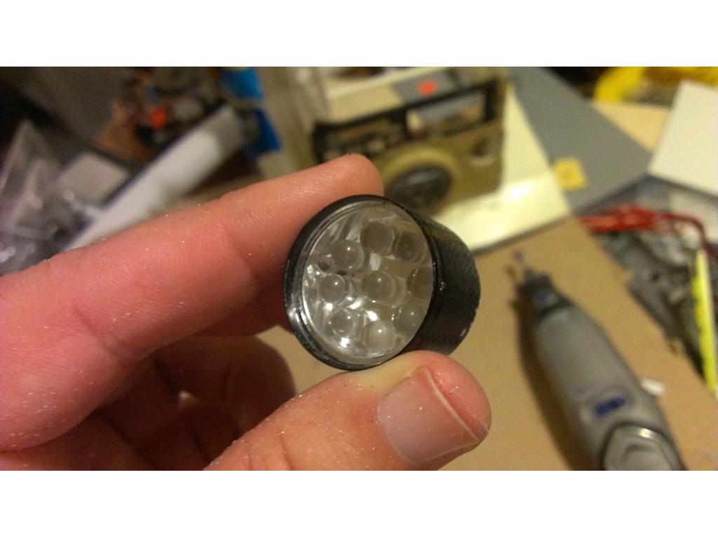
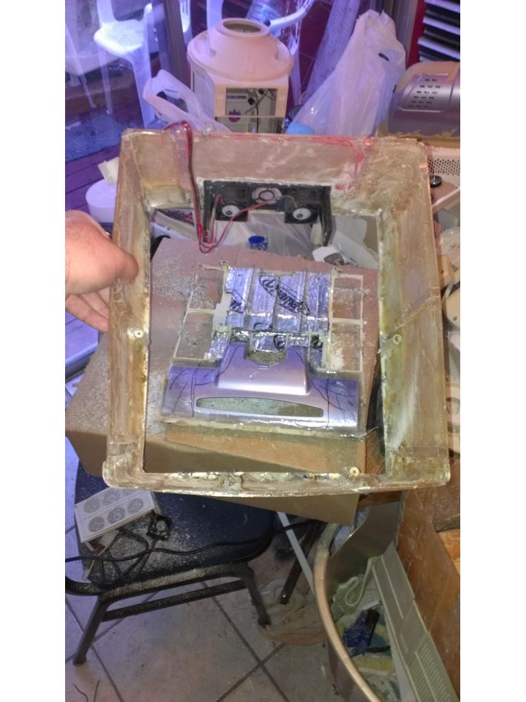
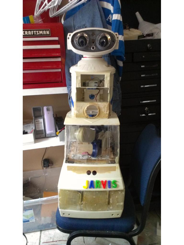
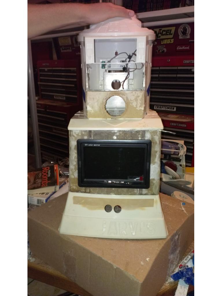
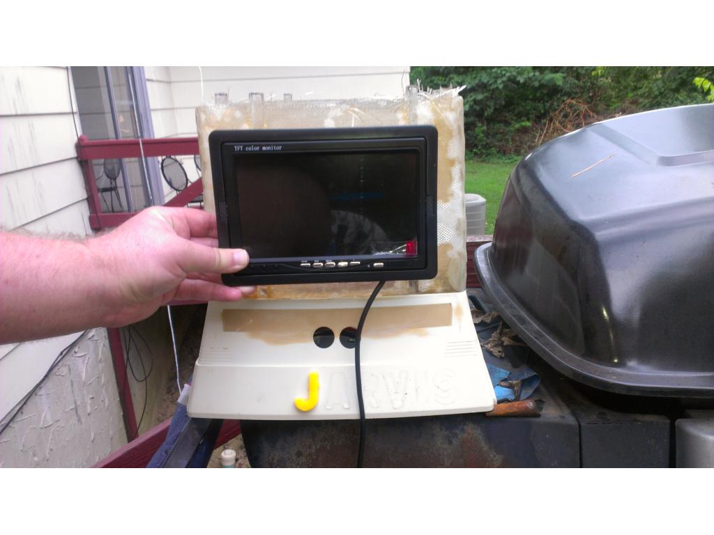
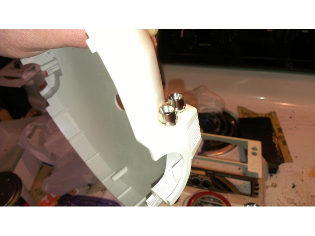
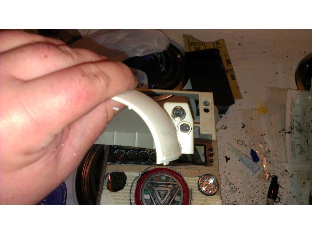
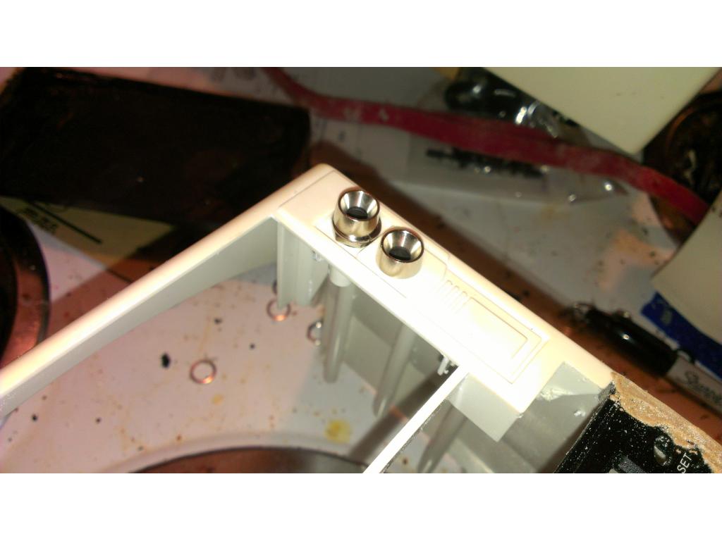
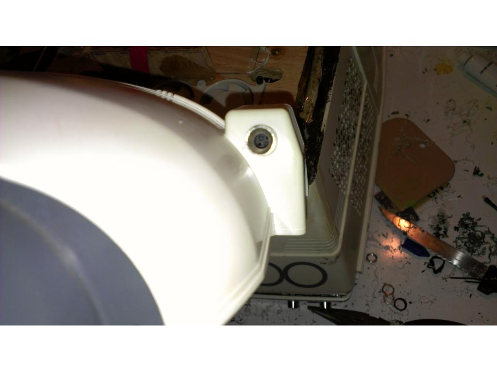
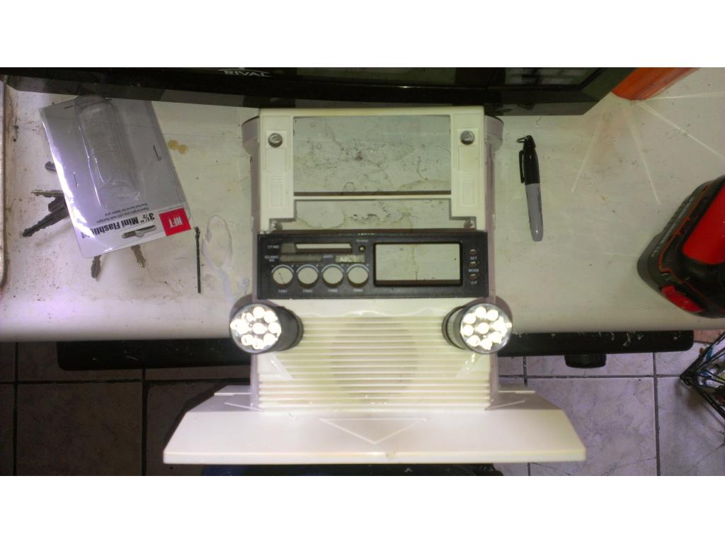
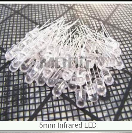
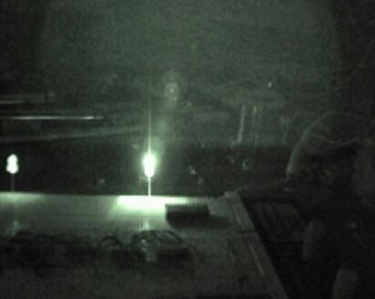
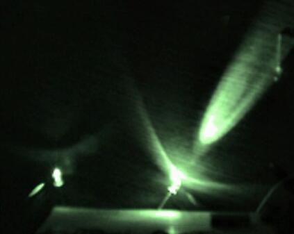
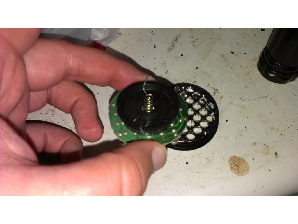
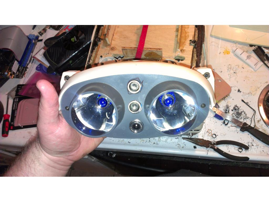
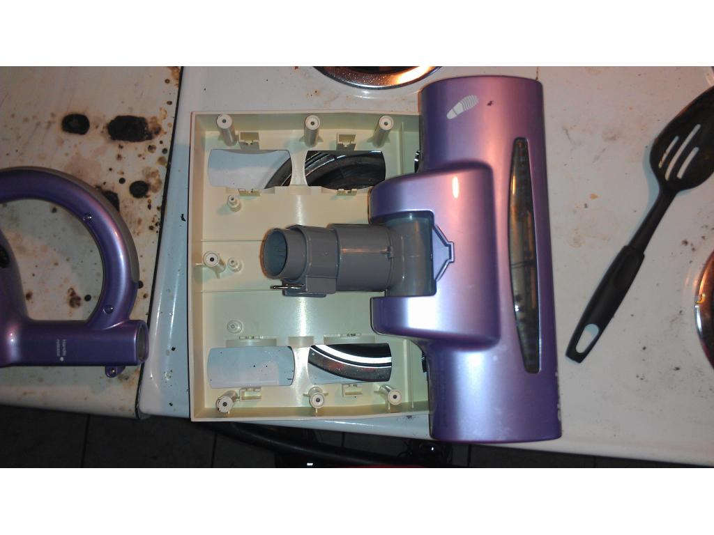
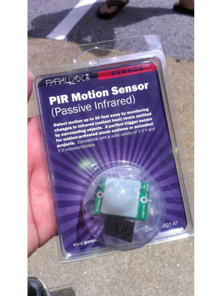
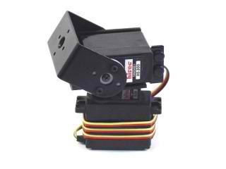
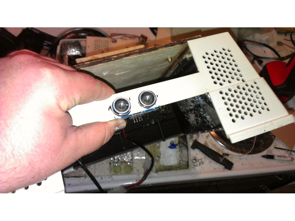
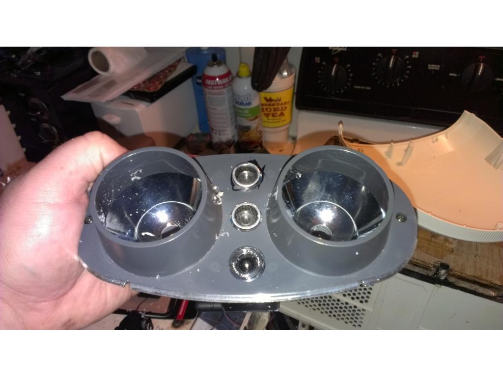
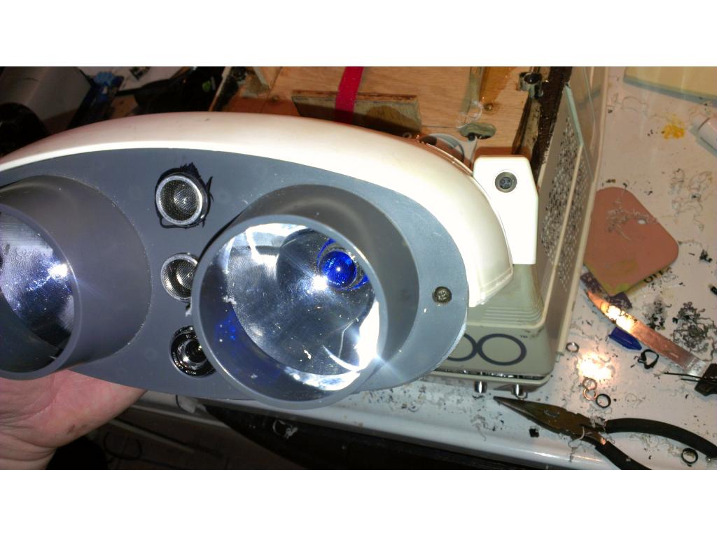
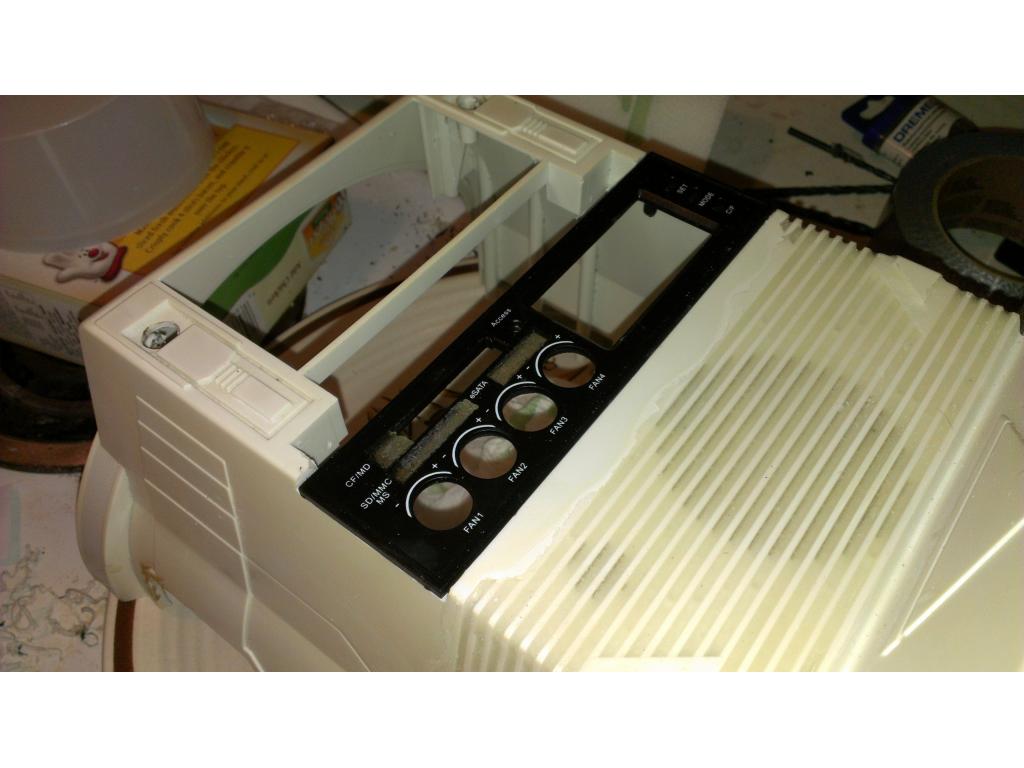
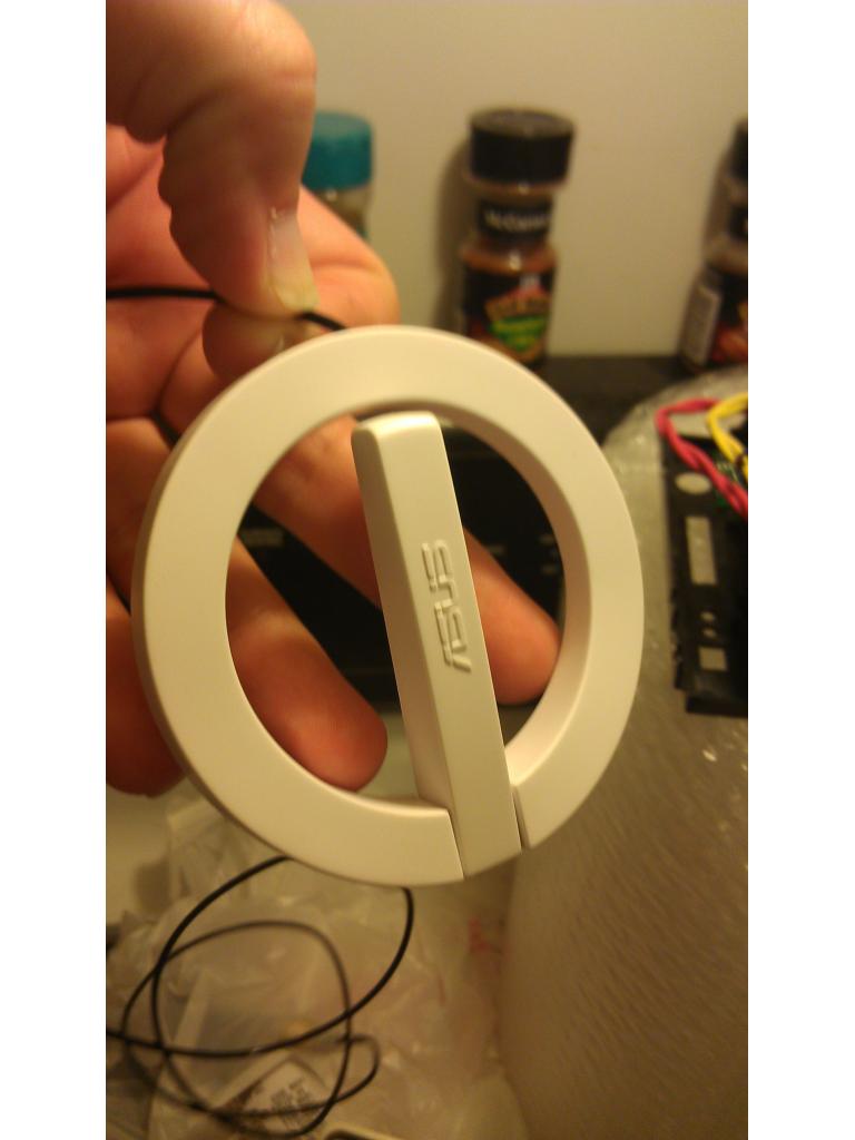
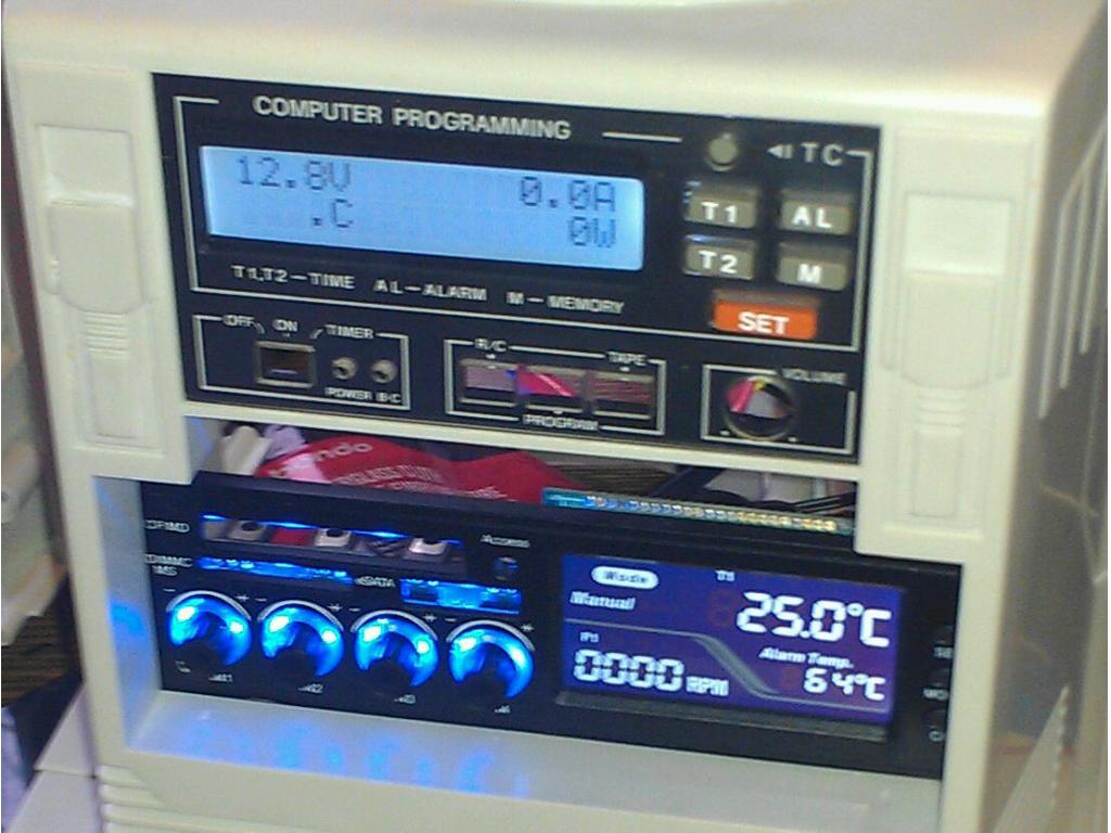
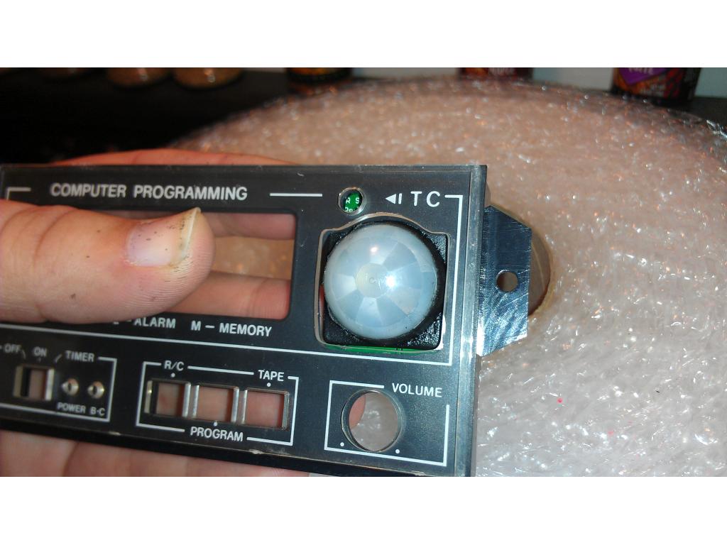
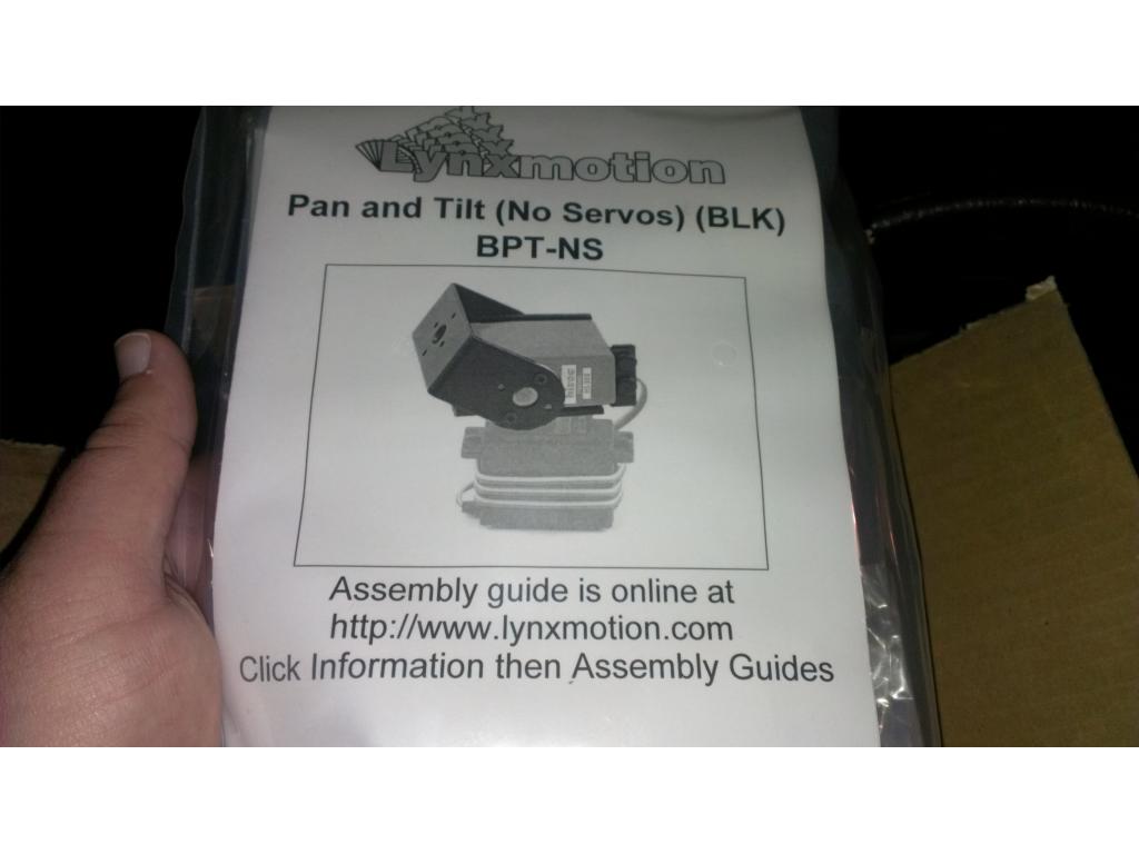
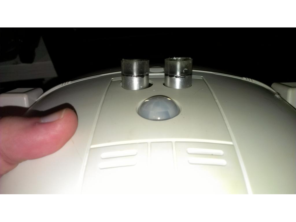
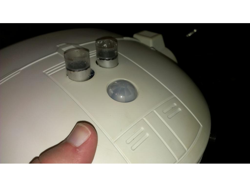
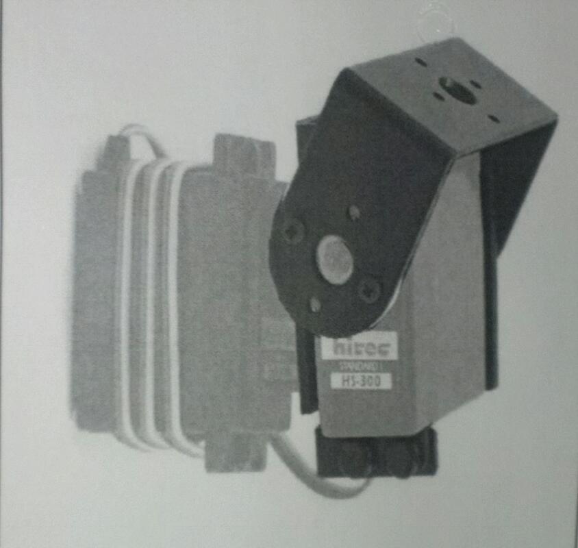
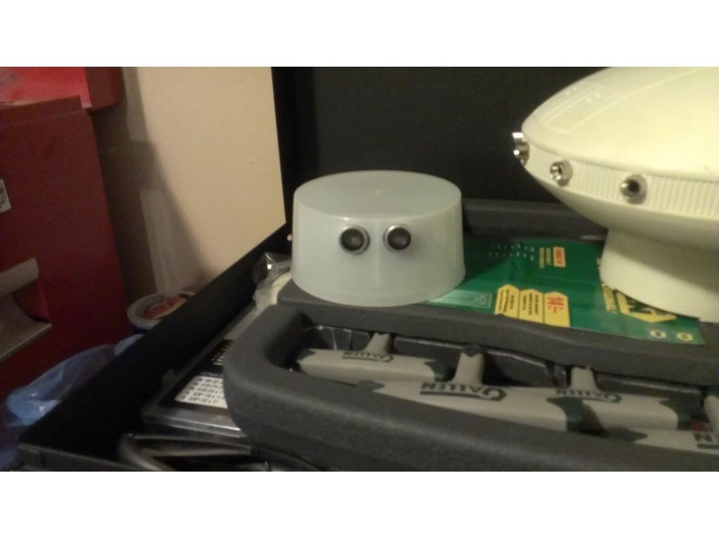
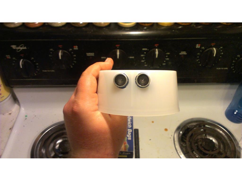
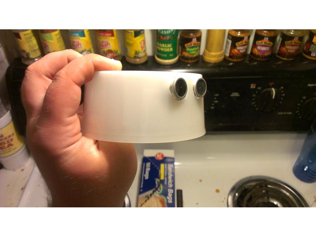
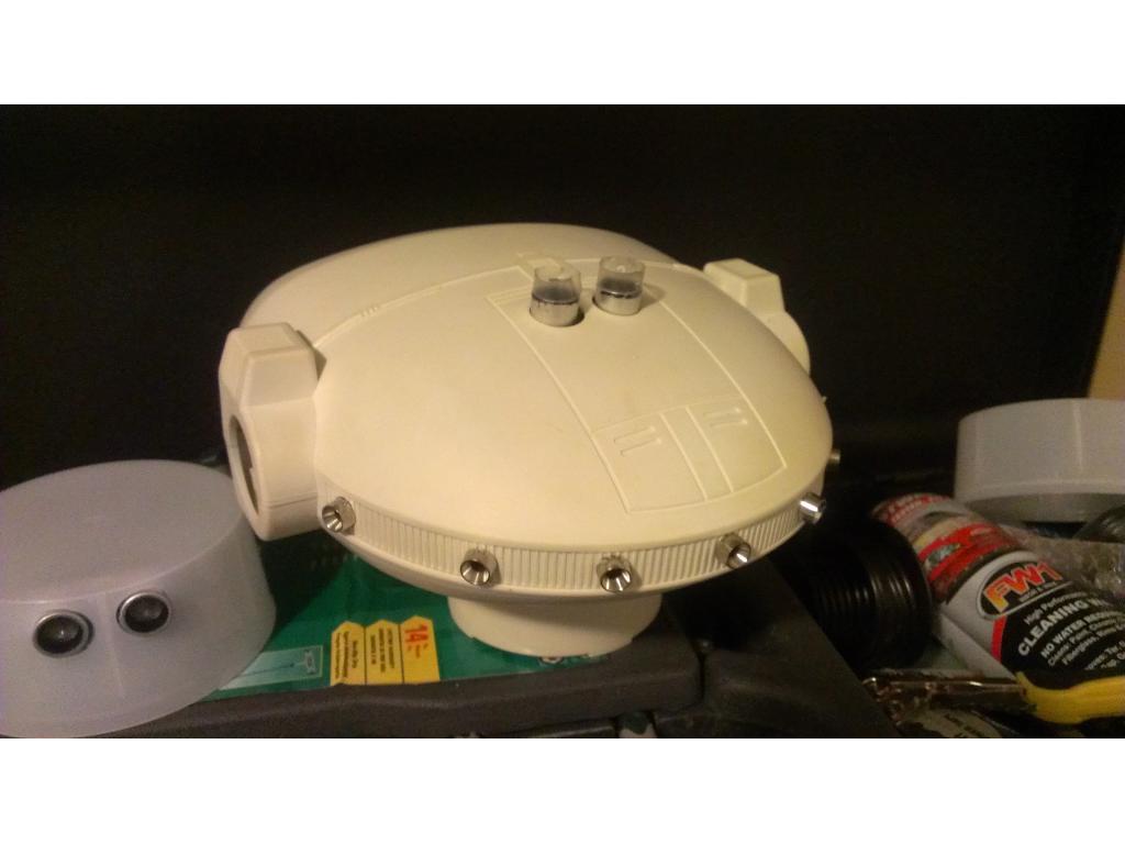
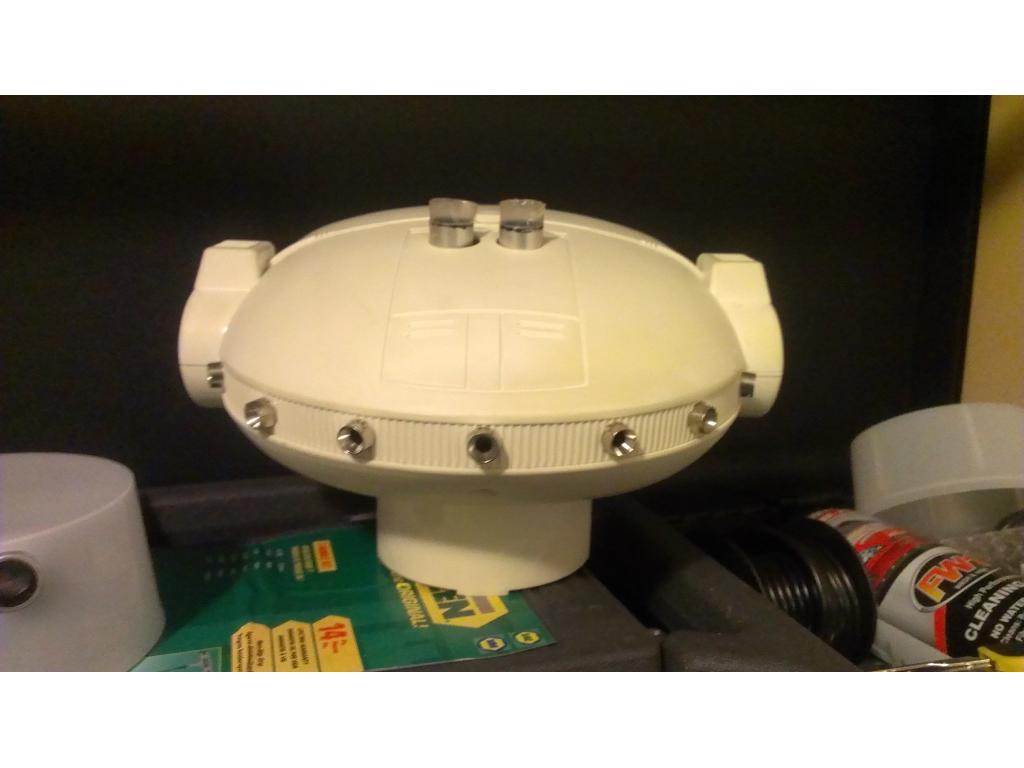
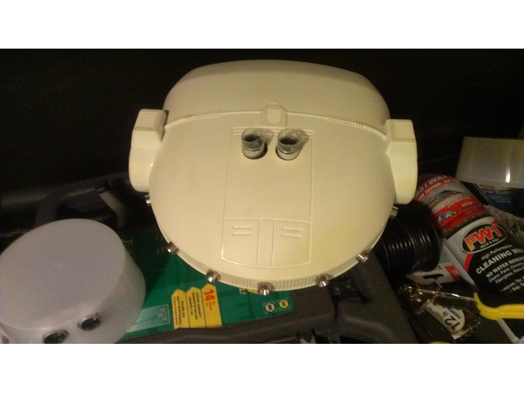
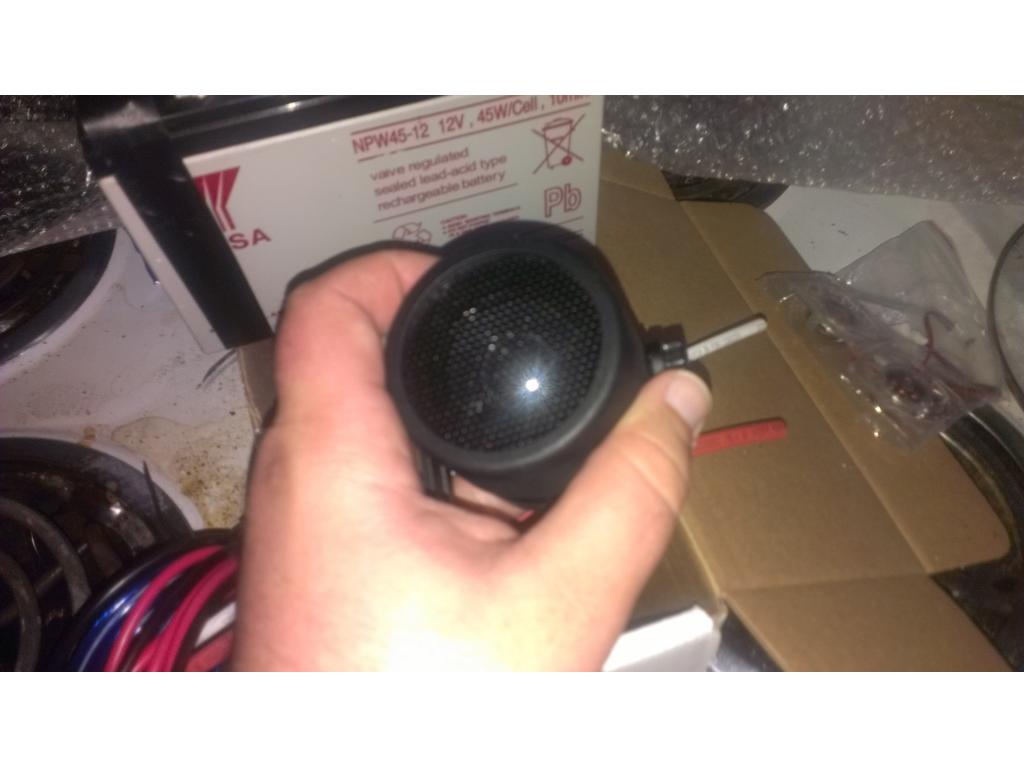
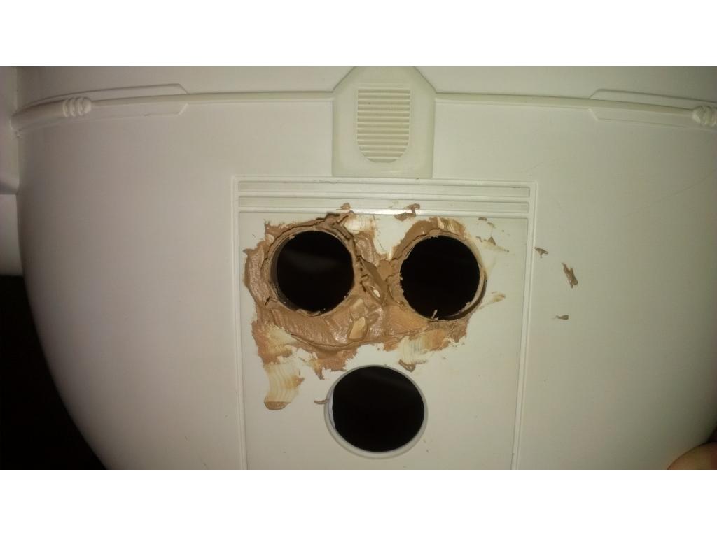
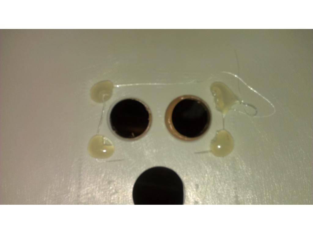
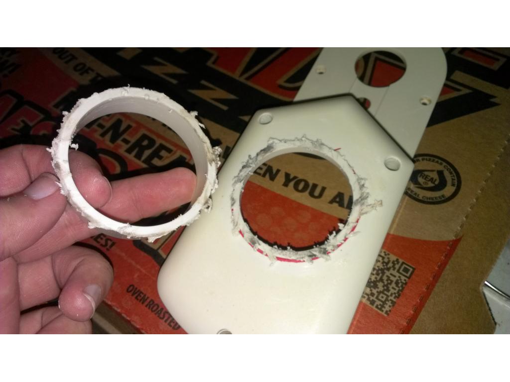
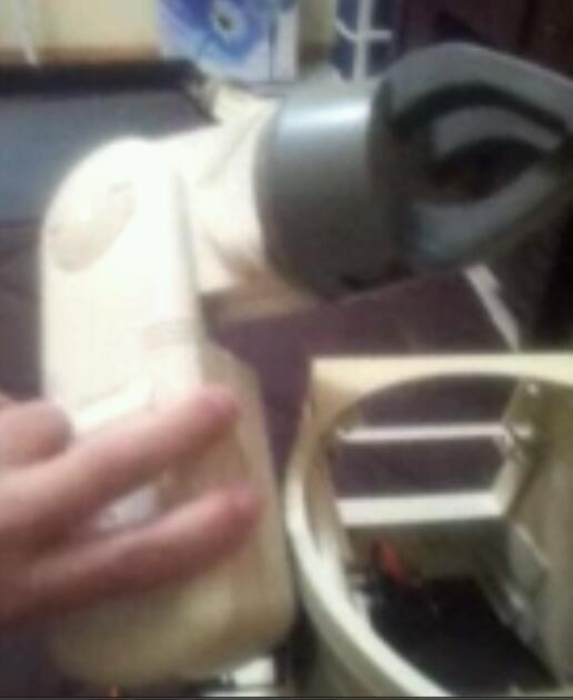
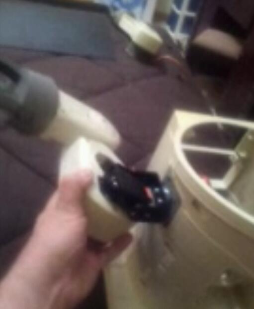
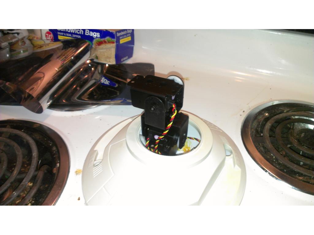
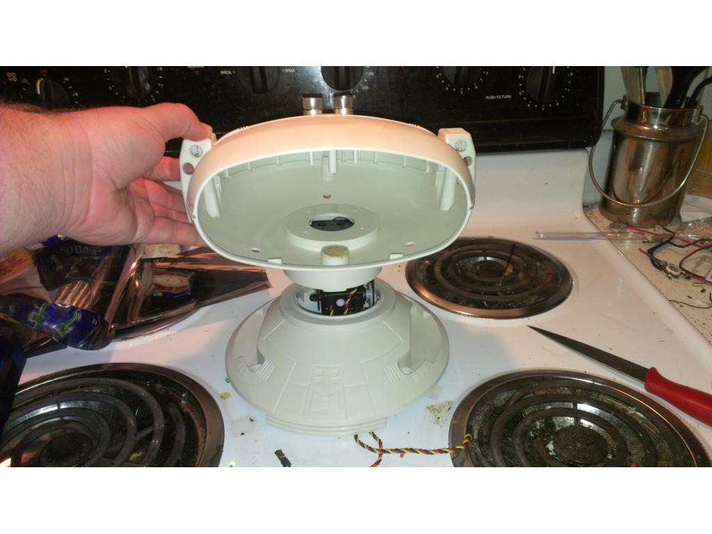
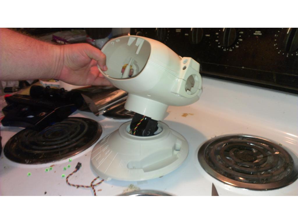
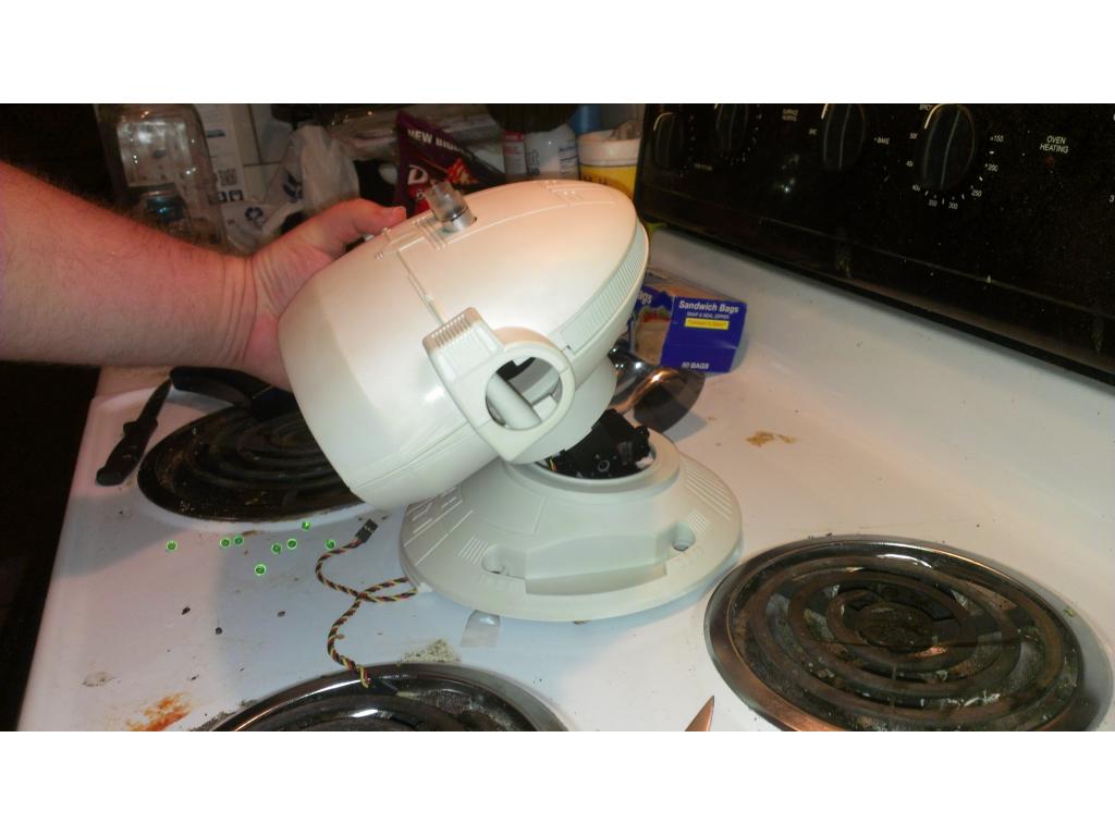
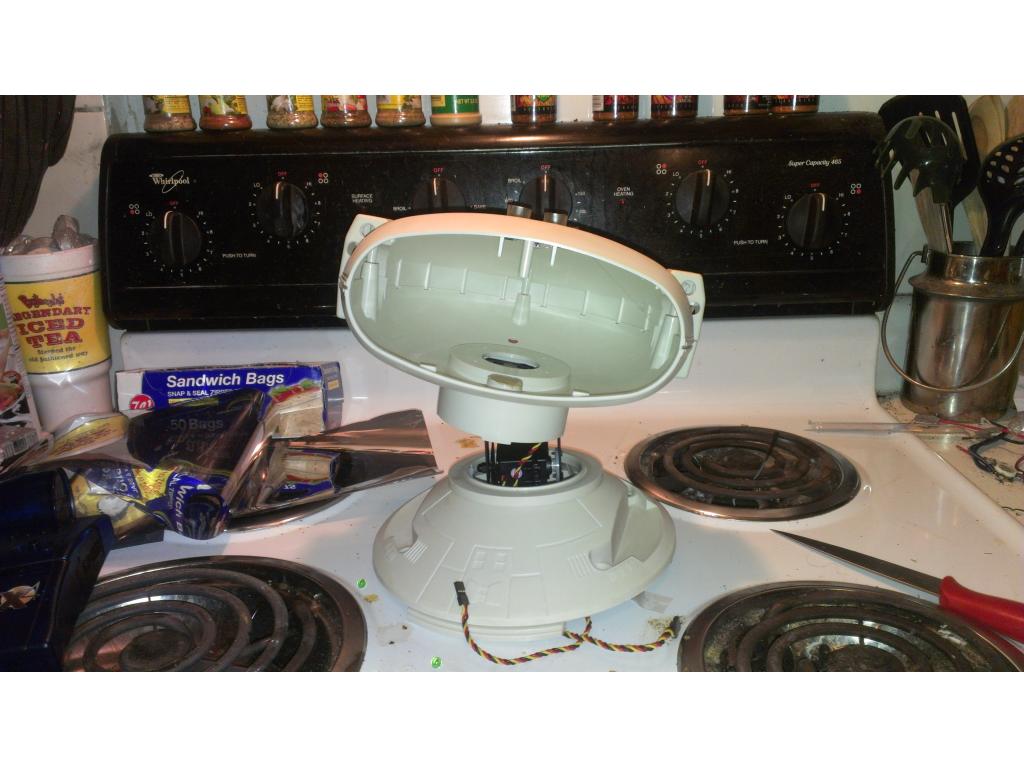
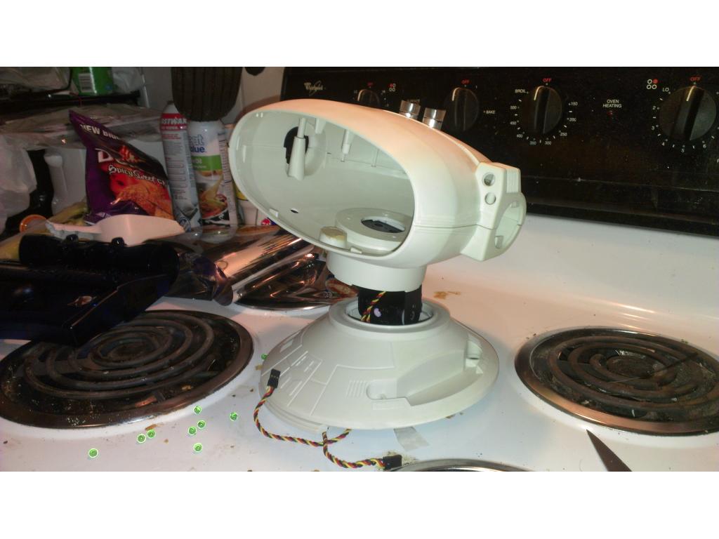
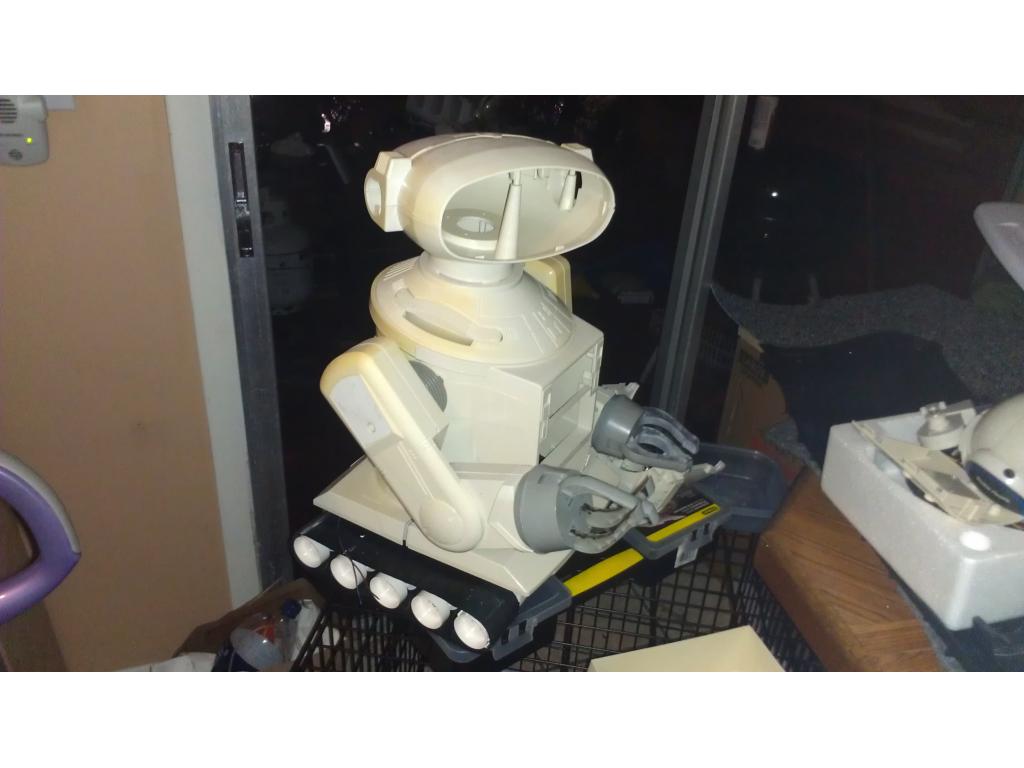
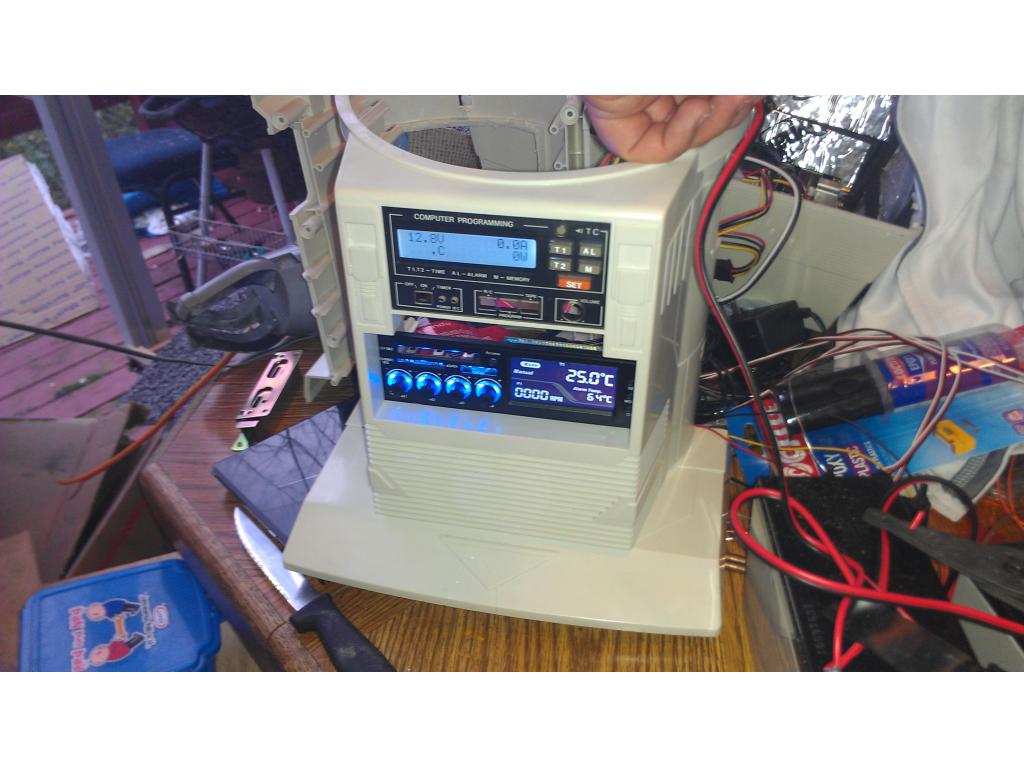
Pan and tilt bracket for Jarvis main radar sensors. Ultrasonic and IR as backup