Asked
— Edited
Wall-E Led
How did DJ connect wall-e's led for his eye to the ez-b?
 NMS Example
— Example NMS Level #1 navigation skill showing subscription to combined scan+location data, displaying position and scan info; source code included.
Try it →
NMS Example
— Example NMS Level #1 navigation skill showing subscription to combined scan+location data, displaying position and scan info; source code included.
Try it →

I assume he used the darlington transistor switching circuit and used one of the digital ports to enable/disable the light.
ok is there a simpler method to this(limited abilities cause i'm 12)
In short, no.
The circuit I posted is very simple, you wont find simpler short of wiring the signal wire to the LED - which is not advised as the signal wire doesn't carry anywhere near enough current to power anything.
You can do the circuit either in line (how I did mine), on a prototype board or on a breadboard (solderless).
Why do you want it simpler? If you let me know what you want to avoid doing I may be able to tell you the best way to go about it.
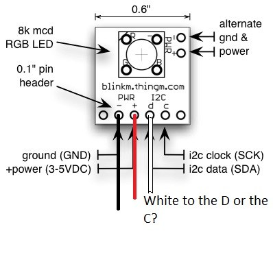
well, could the blinkM or what ever he mentioned in hardware compatibility work about the same? By the looks it does more but the setup would be easy right? synthiam.com/Tutorials/Hardware.aspx?id=12
hold on for a sec im trying to answer my own question(tired from sledding)
Here is another wiring diagram which may make it look simpler.
And my in line version (however the resistor is hidden by heat shrink)
didnt find anything but did find this cool android robot. www.youtube.com/watch?v=2hXYXUMu2Ik
seems a little simpler.