rgordon
USA
Asked
— Edited
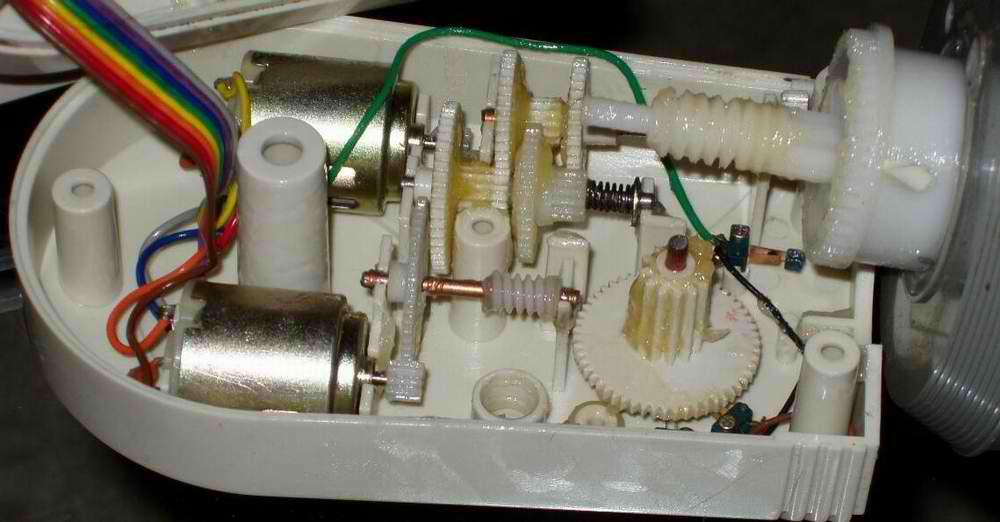
Turn Dc Gear Motors Into A Servo
Hey guys,
Anyone tried something like this yet? This may be what I need to use for my arm motors.
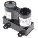 Lidar-Lite Laser Module
— Laser Lidar-Lite ARC control reads distance, velocity and signal strength (0-40m+) via EZ-B v4 i2c, setting EZ-Script vars for robotics
Try it →
Lidar-Lite Laser Module
— Laser Lidar-Lite ARC control reads distance, velocity and signal strength (0-40m+) via EZ-B v4 i2c, setting EZ-Script vars for robotics
Try it →
Hey guys,
Anyone tried something like this yet? This may be what I need to use for my arm motors.

Interesting. I too have been searching for something to move my arms and give me the strength I want. This seems like a very inexpensive alternative to what I had found. I see using a simple dual H bridge to control forward and reverse. Hmmm
Indeed...
How many H-Bridge's can I control with the EZ-B? Do you hook them to the same port as a servo? (I'm still trying to gather the $ to order my EZ-B)
@ rgordon , That depends on the interface for the H bridge from what I have found. The one DJ sells on his site uses only one port i think. I have one in my bot that uses 4 (one each L/R for motor speed and one each L/R for motor polarity). You can also get DC motor controller boards like the Pololu pik (controls 2 motors) from Sparkfun that only uses one port with serial control that could work with a movement script. Hope this helps.
Very interesting post btw....I am definitely going to look into that! I will need some higher power servos for my next project!
v/r
Kevin
@ kkeast,
I will have 4 motors in each arm: shoulder, elbow, wrist, and claw. I guess I could use servos for the wrist and claw but the shoulder and elbow will definitely need some high torque gear motors.
So you are controlling the speed and direction of 2 motors with 4 ports? Is this what you are saying?
I will look into the Pololu pik you mentioned.
Thanks
@ rgordon , Yes, two motors with 4 EZB ports.
Here is an example of my movement script for turning Left
set(d18,on) set(d8,off) set(d19,on) set(d9,on) sleep(1000) set(d19,off) set(d9,off)
I am not adjusting speed right now, however the board claims it will accept PWM for speed control (which would be using PWM for D19 and D9 in the above example instead of OFF/ON). Now that DJ has the PWM control I might be able to do that...but I did notice there is no script command for setting that....yet (not sure if servo(DX,XX) will work for that?)
Hope this answers your question.
v/r
Kevin
So if I use H-Bridges I'll need (8) ports : (4) for the L & R shoulder DC gear motors and (4) for the L & R elbow DC gear motors.
Then I would need 4 servo ports : (2) for the L & R wrist servos and (2) for L & R claw servos.
(1) port for the neck servo.
(1) port for the waist servo. (I have not purchased this one yet)
Presently I am using two Victor 883 ESC's for controlling the wheelchair motors using a Spektrum DX6 transmitter and BR6000 Bot Rcvr. I want to use the EZ-Board to control my drive system. So will the ESC's need PWM? Will my EZ-Board have enough ports to do what I need to control these as well?
I have not received my EZ-B yet. I'll probably have a ton more questions when I start messing around with it. Thanks for the script example and all your advice. Every little bit helps. That's what I like about this site..everyone is very helpful.
BTW I live in Nelson, Virginia.
@ rgordon ,
I think there are a few of us from the Tri State area on here.... a Mid Atlantic get together has been proposed..which would be a great thing to do at some point!
Answer to your question...Two H Bridges if you also want to control elbow motors as well. The only thing I have found with the motors is that you don't know the motor position without some other sensor device (wheel encoder, hall effect sensor, micro-switch). Motors work great if all you want is remote control but definitely a challenge if you want to do autonomous things. You also get the torque of course! Are you planning on implementing the above solution you presented?
Electronic Speed Controls plug in just like standard servos (so I am told). Check this thread out for more on that. Trick is to find ESCs that do both forward and reverse that meet your motor current requirements. They have them but I tend to go back to the H bridges due to cost.
Electronic Speed Control Thread
v/r
Kevin
In the article above it seems like he is using the servo itself as position and speed control of the DC motor, by tying the servo arm to the motor arm. That way the servo has something to measure speed and position. Interesting.... I may need to experiment this weekend.