Asked — Edited

Serial Toolbox Plugin

@PTP

I have read over the tutorial on making plugins and it was very good and helpful. I am looking to do a plugin using the serial port on the ezb to communicate with an arduino type board to communicate back and forth with various sensors, lcd's, etc.

I was wonering if I could get your source code for the serial toolbox plugin to learn from regarding serial port communications with ezb, etc. I am also taking a course on c# but there is nothing like actual examples of code when it comes to communicating with hardware serial ports. Most all courses don't go into this type of coding. Thanks much....Rick. :) :)


ARC Pro

Upgrade to ARC Pro

Take control of your robot's destiny by subscribing to Synthiam ARC Pro, and watch it evolve into a versatile and responsive machine.

PRO
Synthiam
#1  

All the serial commands for the ezb can be found in...

EZ_Builder.EZBManager.EZB[0].Uart

#2  

@DJ

Thanks much, that helps but there is nothing like having a completed and working example to look over and learn from. The serial toolbox covers alot more than what was included in your awesome tutorial on plugins...Rick. :)

#3  

@DJ

Also curious as to how the serial plugin handles the arduino side of things...Rick.

PRO
USA
#4  

Only to give a little bit of context. Rick sent me an email requesting some help to integrate an Arduino with ARC.

I will start by saying that: Arduino is not EZ you can easily open the IDE, copy paste some code, compile, flash and run.

But if you need to dig in you will need to know C/C++ language, how the libraries work, board specific details, code optimization, troubleshooting without breakpoints, limited memory, limited resources, interrupts, timers etc, etc.

PRO
USA
#5  

Hardware used:

  1. Arduino UNO
  2. EZB V4

Arduino:

Power = USB/Cable Pins 0 - RX - Grey wire 1 - TX - Purple wire 3 - Red wire 5 - Green wire 9 - Blue wire GND - Black wire 5V - Orange wire

RGB Led (Common Cathode)

Red Led - Red wire Green Led - Green wire Blue Led - Blue wire 5v - Orange wire

EZB

Power = 7.5v Power supply Uart 0 - RX - Purple wire Uart 0 - TX - Grey wire Uart 0 - GND - Black wire (Common Ground)

PRO
USA
#6  

Arduino Code:

  1. Libraries To make the process less complicated, i created an Arduino library called SerialCommands you can grab from here:

https://github.com/ppedro74/Arduino-SerialCommands

Please download the and install the arduino library.

i opened a ticket to publish the library via Arduino IDE tool, later you will be able to search and install automatically via Arduino IDE.

  1. Example project: https://github.com/ppedro74/ArduinoPlayground/blob/master/TestSerialCommands/TestSerialCommands.ino

Compile and flash!

Note: When flashing an Arduino with a single Serial Port (Atmega328, Atmega168) disconnect the RX/TX cables (EZB side) to avoid interferences.

PRO
USA
#7  

Test Arduino Code:

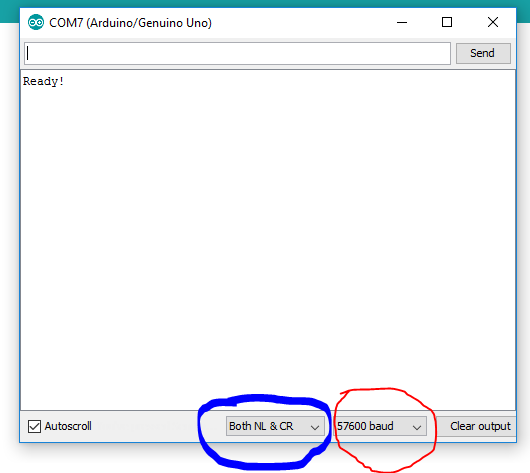
Open the Arduino Serial Console:

User-inserted image

Blue Note: When sending serial commands the existent code expects the CR & LF to end a line

Red Note: 57600 bps is intentional ! All micro-controllers have different clocks, when working with serial communications both sides (RX / TX) agree on a specific BaudRate / Clock, unfortunately 115200 bps @ atmega328 is not 115200. So let's use 57600.

more here: https://arduino.stackexchange.com/questions/296/how-high-of-a-baud-rate-can-i-go-without-errors

The arduino code (relevant part)


SerialCommand cmd_read_analog_("READ_ANALOG", cmd_read_analog);
SerialCommand cmd_set_led_("SET_LED", cmd_set_led);
SerialCommand cmd_start_push_("START_PUSH", cmd_start_push);
SerialCommand cmd_stop_push_("STOP_PUSH", cmd_stop_push);

accepts the following commands: READ_ANALOG, SET_LED, START_PUSH, STOP_PUSH

some examples:


//reads analog port 0
READ_ANALOG 0

//read analog port 1
READ_ANALOG 1

//read analog port 2
READ_ANALOG 2

//set red led (ON) RGB Led (Common Cathod/255-Off, 0-ON)
SET_LED 0 red

//set red and green led (OFF) 
SET_LED 255 red green

//set red and blue led (HALF bright) 
SET_LED 128 red blue

//request ping push messages every 1000 ms
START_PUSH 0 1000

//request analog push messages every 3000 ms
START_PUSH 1 3000

//stop ping push messages
STOP_PUSH 0

//stop analog push messages
STOP_PUSH 1

The above commands are examples how:

  1. Set actions (SET_LED) (Note: multiple parameters example)
  2. Read Values (READ_ANALOG)
  3. Monitoring values / Pushing results (START_PUSH / STOP_PUSH)

After submitting the above commands:

User-inserted image

Note: After the START_PUSH the arduino code starts pushing messages to the console. This can be modified to instruct the Arduino to perform some action or monitor a sensor and report the values back with a specific frequency or a specific trigger, all depends the code logic.

PRO
USA
#8  

ARC Side

To be continued...

PRO
USA
#9  

reserved 5

PRO
Synthiam
#10  

nice! ptp, have you thought of making this a user tutorial? rather than a forum post... Look here: https://synthiam.com/Tutorials/UserTutorials/

PRO
Canada
#11  

Thanks for putting this together. One area I was struggling with when talking to the UART was sending multiple commands at once and waiting for answers to come back. I have to do it one command at a time. Send request, wait for aknowledgment, and then act. Example I am reading the position of a dozen servos and then mirror the servos with a second set to mirror the position of the first set of Servos. Unfortunately this means I have to send individual get location requests, wait for acknowledgement, process data checking for CR LF and then send to new Servo. Then repeat for next one.

What would be better if I could send a command to arduino to say keep checking servo locations if nothing changes don’t talk to me but if one changes send me a messsage.

I haven’t had a chance to get around to this yet but would be nice if we had a way to reduce chatter between two devices.

PRO
Synthiam
#12  

Nink, if you're creating the application protocol yourself - meaning you get to define the commands and what to expect in response...

So if that is the case, do not terminate. And you generally see some "command packets" have a silly checksum. That's silly in this day of age... specifically with TCP already embedding sanity checks. And to communicate over UART, well... it's pretty difficult in this day of age to have a single byte go unnoticed. Back in the day... and i mean like 20-30 years ago when cpu's were slow and interrupts were rare... that's when sometimes a byte could go unnoticed.

Anyway - the next thing is the command and termination. So yeah, don't terminate. Create a list of commands and their expected response size. That way you can cut the transmission speed and processing significantly.

Take for instance if your command is 1 byte, and your termination is 2 bytes (crlf). That's 3 bytes per transmission. And if your response is 1 byte, but terminated with 2 bytes (crlf) then that's 3 bytes for transmission. That's a total of 6 bytes to do one little thing. If you didn't terminate, and had an expected list of commands and their length, then you'd cut that transmission size by 300%! So if you were to transmit 100 commands, with a CRLF you'd actually be transmitting 300 Bytes vs 100 Bytes. HUUGGE difference with volume! (three times as much...)

Now, we've only reviewed the datasize. We haven't touched on the processing aspect. Part of the discussion is "oh now i have to parse the data blah blah blah". Why do you have to parse data? Never parse data. Parsing data when you should know what to expect is unnecessary. If you're in control of the data, don't design it to be parsed. CPU processing time is a luxury, not a right :D

Have you taken a look at the ez-b communication protocol datasheet? That will give you an idea of how to implement an application protocol of your own.

Here, take a look at this: https://synthiam.com/Tutorials/Lesson/18?courseId=4

PRO
Synthiam
#13  

While you add to that, let me expand on what an efficient application protocol should look like...

What i recommend is, if you only need to set and receive servo positions, is to use the 7th bit to determine SEND or RECEIVE. That gives you 127 servos you can send or receive to.

So to SEND a command, have it like this...

COMMAND, POSITION (0-127), (0-255) i.e. Move servo 0 to position 50:


# Initialize the port, obviously only do this once upon connection
UARTInit(0, 0, 230400)

DefineArray($DataToSend, 2)
$DataToSend[0] = 0 # servo 0
$DataToSend[1] = 50 # Position 50

UARTWriteBinary(0, 0, $DataToSend ) 

And to get data back... do something like this...


# Initialize the port, obviously only do this once upon connection
UARTInit(0, 0, 230400)

DefineArray($DataToSend, 2)
$DataToSend[0] = 0 + 127 # servo 0. We add 127 to set the last bit to a 1
$DataToSend[1] = 50 # Position 50

UARTWriteBinary(0, 0, $DataToSend ) 

# No point to probe the ezb to see if data is available. Just read it, it'll block while
# it waits for the read. Your slave should already have that data cached anyway 
# so there's no delay in reading.
UARTReadBinary(0, 0, 1, $DataToRead)

print("The servo Position is " + $DataToRead[0])

PRO
USA
#14  

@DJ, Thanks I agree with you a Tutorial will be more easy to follow and update. I'll finish this thread, and use the user feedback to create a tutorial.

@Nink I'll provide examples how the plugin can help for different scenarios sync and async data responses.

...

This a text protocol, is not optimal neither bullet proof but it's EZ to debug and test and improve but there some limitations: message size and text only.

So if you want to send sound bytes or bitmap bytes you need to develop a custom protocol similar to the EZ-Robot.

...

I've a custom robot, and I'm using multiple mini controllers to solve different problems (time sensitive) and HID (Human Input Devices) related e.g.

  1. multiple push button keypad
  2. multiple leds
  3. oled 128x64
  4. other sensor devices.

I like the concept of building blocks, so each problem is solved with a micro-controller, but in the end they need to communicate with a master controller EZB or a Host.

Each device sends and receives data sync and async, so I2C does not fit, so I'm using serial (tx,rx).

If each device requires a serial port, soon or later you will run out os UART ports.

So each device has two or more serial devices, and they relay/route the messages using their serial ports, so you can have a Host with a single port communicating with N inline serial devices or you can have a network with multiple nodes (redundant paths or alternative more/less hops)

I couldn't find anything simple (Library) to use so this is another mini project i'm working on.

PRO
Synthiam
#15  

Okay - now last part of the lesson :D

Once you have a good working EZ-Script that sends and receives your servo commands, turn those into EZ-Script functions as a plugin. The neat thing about ARC is you can extend the capabilities, including ez-script. So you can create a plugin that registers the commands...


# Move servo 0 to position 50
SetMyCustomServoArduinoThingy(0, 50)

# Get servo 2's position
$x = GetMyCustomServoArduinoThingy(2)

You can do this by following this part of the plugin tutorial: https://synthiam.com/Tutorials/UserTutorials/146/22

PRO
Synthiam
#16  

ptp, add an address byte at the beginning of each command - that way all other controllers ignore the command if it's not addressed to them.

something like..

[ADDRESS], [COMMAND], [DATA]

PRO
Canada
#17  

Thx @DJ and @PTP If you have a look at my code I am trying to interface with Meccanoid bios but the commands are structured and responses come back and I don't really know the size of the packet (could be 4 or 5 bytes. I wrote my own error check and put a wait in after 4 bytes but I really need to redo the meccanoid bios to make this work effectively. I also need to create a unique ID on each packet and then queue them but .....

Goal was to build 1 JD from meccanoid servos and 1 from EZB servos and mirror the second one off the first one (Move left arm on first JD and Left arm on second JD moves) I have 2 read and 2 write servo's working now but it's messy.


# To use this you need meccontrol firmware
# The commands are well documented here
# https://meccontrol.com/help/firmware/communication-protocol

# Initialize UART to 9600bps
UARTInit(0, 0, 9600)

# Set servo Degrees
$ServoDegrees0=120
$ServoDegrees1=120


# MeccanoidInitialise Resets all Servos on Pin 2
$command="MeccanoidInitialise 2"
Goto(SendCommand)

# MeccanoidSetServoMotorPosition (MNSSMP is Shortform) pin 2, servo 0, 120 degrees 0ms
$command="MeccanoidSetServoMotorPosition 2 0 120 0"
Goto(SendCommand)

# MeccanoidSetServoMotorPosition pin 2, servo 1, 120 degrees, 0ms
$command="MeccanoidSetServoMotorPosition 2 1 120 0"
Goto(SendCommand)

# MeccanoidSetServoMotorPosition pin 2, servo 2, 120 degrees, 0ms
$command="MeccanoidSetServoMotorPosition 2 2 120 0"
Goto(SendCommand)

# MeccanoidSetServoMotorPosition pin 2, servo 3, degrees, 0ms
$command="MeccanoidSetServoMotorPosition 2 3 120 0"
Goto(SendCommand)

## Disbale Red Servos

# MeccanoidDisableServoMotor pin 2, servo 0
$command="MeccanoidDisableServoMotor 2 0"
Goto(SendCommand)

# MeccanoidDisableServoMotor pin 2, servo 1
$command="MeccanoidDisableServoMotor 2 1"
Goto(SendCommand)

## Set Disabled Servos Red

# MeccanoidSetServoLEDColour pin 2, servo 0, red
$command="MeccanoidSetServoLEDColour 2 0 1"
Goto(SendCommand)

# MeccanoidSetServoLEDColour pin 2, servo 1, red
$command="MeccanoidSetServoLEDColour 2 1 1"
Goto(SendCommand)

## Set Active Servos Green
# MeccanoidSetServoLEDColour pin 2, servo 2, green
$command="MeccanoidSetServoLEDColour 2 2 2"
Goto(SendCommand)

# MeccanoidSetServoLEDColour pin 2, servo 3, green
$command="MeccanoidSetServoLEDColour 2 3 2"
Goto(SendCommand)

# # Check to See if a servo Is Moved and stop > 230 degrees
repeatuntil($servoDegrees0 > 230)

  # make movecheck = servo degress to see if moved
  $moveCheck0=$servoDegrees0

  # MeccanoidGetServoMotorPosition pin 2, servo 0
  $command="MeccanoidGetServoMotorPosition 2 0"
  Goto(SendCommand)

  # convert $readData to degrees
  $arraySize=GetarraySize("$readData")


  # Check 5 fields and Carriage Return Line Feed (13,10) and buffer of 4
  if ($arraySize=5 AND $readData[0]=49 AND $readData[$arraySize-1]=10 AND $readData[$arraySize-2]=13 AND $bufferSize=5 )

    # Convert First field of array to ASCII
    $degreesString00=GetAsByte($readData[0])
    $degreesString01=GetAsByte($readData[1])
    $degreesString02=GetAsByte($readData[2])

    # Build Command MeccanoidSetServoMotorPosition (MNSSMP is Shortform) pin 2, servo 0
    $command="MeccanoidSetServoMotorPosition 2 2 "
    $command=$command + $degreesString00+$degreesString01+$degreesString02+" 0"

    # Convert First field of array to Decimal
    $servoDegrees0=$readData[0]*100-4800
    $servoDegrees0=$servoDegrees0 + $readData[1]*10-480
    $servoDegrees0=$servoDegrees0 + $readData[2]-48

    # Check 4 fields and Carriage Return Line Feed (13,10) and buffer of 4
  ELSEif ($arraySize=4 AND $readData[$arraySize-1]=10 AND $readData[$arraySize-2]=13 AND $bufferSize=4)
    # Convert First field of array to ASCII
    $degreesString00=GetAsByte($readData[0])
    $degreesString01=GetAsByte($readData[1])

    # Build Command MeccanoidSetServoMotorPosition (MNSSMP is Shortform) pin 2, servo 0
    $command="MeccanoidSetServoMotorPosition 2 2 "
    $command=$command+$degreesString00+$degreesString01+" 0"

    # Convert servo Position to degrees
    $servoDegrees0=$readData[0]*10-480
    $servoDegrees0 + $servoDegrees0=$readData[1]-48
  endif

    # clear out uart buffers
  $bufferSize=UartAvailable(0,0)
  UARTReadBinary (0, 0, $bufferSize, $garbage)
  Print("Degrees servo 0 = " +$servoDegrees0)
  if ($servoDegrees0 >1 AND $servoDegrees0 < 230)
    if ($moveCheck0!=$servoDegrees0)
      Goto(SendCommand)
    endif
  ELSE
    halt[]
  endif

    ## NOW REPEAT EVERYHTING AGAIN FOR servo 1 #####
    # Need to clean and merge with servo 0#
    # make movecheck = servo degress to see if moved
  $moveCheck1=$servoDegrees1
  # MeccanoidGetServoMotorPosition pin 2, servo 1
  $command="MeccanoidGetServoMotorPosition 2 1"
  Goto(SendCommand)

  # convert $readData to degrees
  $arraySize=GetarraySize("$readData")


  # Check 5 fields and Carriage Return Line Feed (13,10) and buffer of 4
  if ($arraySize=5 AND $readData[0]=49 AND $readData[$arraySize-1]=10 AND $readData[$arraySize-2]=13 AND $bufferSize=5 )

    # Convert First field of array to ASCII
    $degreesString10=GetAsByte($readData[0])
    $degreesString11=GetAsByte($readData[1])
    $degreesString12=GetAsByte($readData[2])
    
    # Build Command MeccanoidSetServoMotorPosition (MNSSMP is Shortform) pin 2, servo 0
    $command="MeccanoidSetServoMotorPosition 2 3 "
    $command=$command + $degreesString10+$degreesString11+$degreesString12+" 0"

    # Convert First field of array to Degrees
    $servoDegrees1=$readData[0]*100-4800
    $servoDegrees1=$servoDegrees1 + $readData[1]*10-480

    # Check 4 fields and Carriage Return Line Feed (13,10) and buffer of 4
  ELSEif ($arraySize=4 AND $readData[$arraySize-1]=10 AND $readData[$arraySize-2]=13 AND $bufferSize=4)
    # Convert First field of array to ASCII
    $degreesString10=GetAsByte($readData[0])
    $degreesString11=GetAsByte($readData[1])

    # Build Command MeccanoidSetServoMotorPosition (MNSSMP is Shortform) pin 2, servo 0
    $command="MeccanoidSetServoMotorPosition 2 3 "
    $command=$command+$degreesString10+$degreesString11+" 0"

    # Convert servo position to degrees
    $servoDegrees1=$readData[0]*10-480
    $servoDegrees1 + $servoDegrees1=$readData[1]-48
  endif

    # clear out uart buffers
  $bufferSize=UartAvailable(0,0)
  UARTReadBinary (0, 0, $bufferSize, $garbage)
  Print("Degrees servo 1 = " +$servoDegrees1)
  if ($servoDegrees0 >1 AND $servoDegrees0 < 230)
    # only move if degrees changed for servo 1
    if ($moveCheck1!=$servoDegrees1)
      Goto(SendCommand)
    endif

  ELSE
    halt[]
  endif


ENDrepeatuntil


Halt()

# Wait Loop as we collect feedback from client
:SendCommand
print("command " +$command)
UARTWrite(0, 0, $command)

$bufferSize=0
# Keep Checking until BufferSize => Target
repeatuntil($bufferSize >= 4)
  $bufferSize=UartAvailable(0,0)
endrepeatuntil

sleep(30) #Wait a bit longer until buffers are full
# now just one more check if it really was all data
$bufferSize=UartAvailable(0,0)
# Now Read the buffers into $readData
UARTReadBinary (0, 0, $bufferSize, $readData)

Return

PRO
Synthiam
#18  

I think you'll need to start by telling us what a "meccanoid bios" is. Is there a data sheet?

PRO
Canada
#19  

Meccanoid BIOS was the original firmware released by Meccano for Meccanoid. It was supposed to be open source but the version they released was not easy to interface with. Some smart folks wrote some code to interface with it (I see there is even a tutorial on EZ-Robot) to control servo's (but they don't read current servo position from it) . It ran on a Arduino.

Meccontrol wrote a better version of the meccanoid BIOS you could interface with, but it was really written to interface with his own app, although he did publish a command interface I mentioned at top of code. Anyway I think I have derailed the thread. I will need to read up on creating plugins.


# To use this you need meccontrol firmware
# The commands are well documented here
# https://meccontrol.com/help/firmware/communication-protocol