
steve.neal
Australia
Asked
— Edited
I seem to be having trouble with one of my Sabertooth/kangaroo motor controllers. The red error light is on and the the motor will not work. Up until now it has been working fine. I suspect what may have happened, (not sure if this is a thing or not), I had the motor/encoder unplugged from the sabertooth and had run the initiation script while testing other things on the robot. I have tried re-auto tuning but this does not help. How do I reset the red error light? Everything seems to be connected. I cant see an obvious reason for it not to work.
Steve

First, let's check if you need one.
Hi DJ
The Voltage measurements with everything plugged in are as follows.
Supply voltage to Sabertooth is 11.99 volts
Voltage measurements at feedback pins of Kangaroo. (As labeled on the Kangaroo)
5V to GND = 5.00 volts GND to A = 15.00 volts GND to B = 15.42 volts A to B = 0.42 volts
I hope this is the information you are after
The motor/encoder I am using is this one https://www.robotgear.com.au/Product.aspx/Details/724-131-1-Metal-Gearmotor-37Dx52L-mm-with-64-CPR-Encoder
Steve
That's the issue - there should only be 5 volts through the encoder. The wiring to the encoder is incorrect - as it should be connected to the +5 of the kangaroo
I'm not certain of the kangaroo can support more than +5 on the encoder logic input pins. It may be damaged.
The motor wires of the motor/encoder should be connected to the HBridge pins of the sabertooth
The encoder power and signal wires of the motor/encoder should be connected to the encoder input of the sabertooth
I have the motor and encoder connected as per this diagram. (only one motor connected to Chanel 1 and the 0V, S1 & S2 connected to the UART port on the EZB) Also I have omitted the index wire.
Is this incorrect for my application?
GND to A = 15.00 volts GND to B = 15.42 volts
I think DJ has something here. The above voltages to A&B of the feedback from the encoder seems very high. I don’t understand why if you are feeding 5v to the encoder (as your reading show, 5v to grd) your getting 15v back on pins A and B.
I need to think about this, go over some specs and test my roo pins to see what I have. My first impulse is there's a short or miss wiring. Dont know how you can get 15v though. The other possibility would be that you can't get a good and understandable read from these pins because of diodes or caps in circuit.
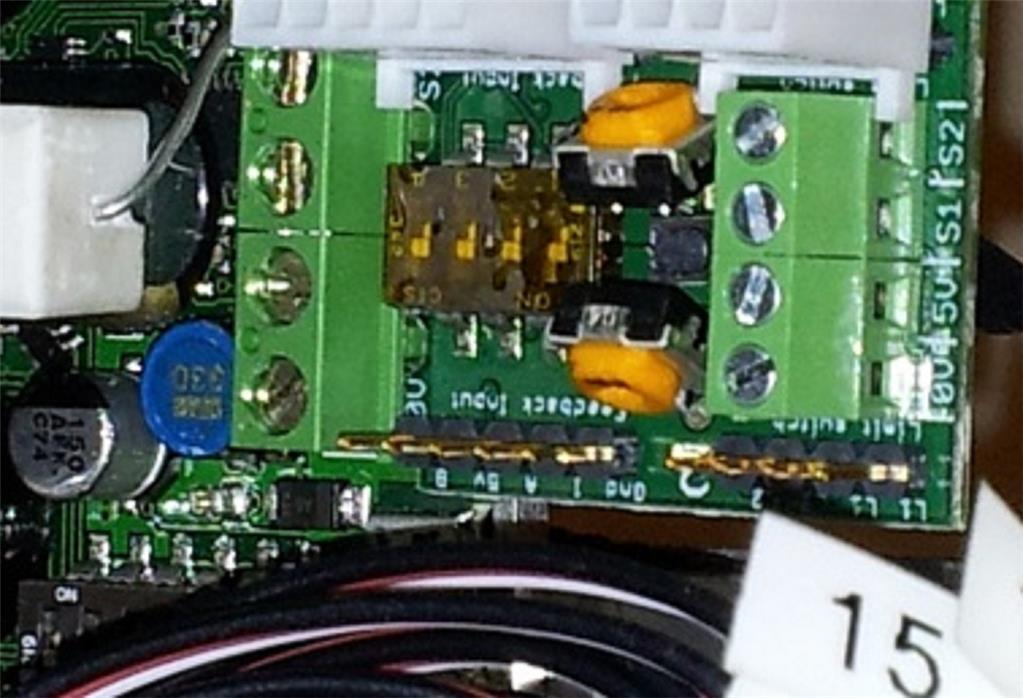
Edit: it's hard to see by your picture but how do you have the dip switches sat on the kangaroo? They should all be in the on position for your application. It kinda looks like they're in the off position. Please confirm this.
Edit again : according to the specs below your encoder input voltage can be as high as 20v so I doubt you damaged it by overvoltage. Double check your wiring to make sure your wiring color map to the proper pins as shown below :
Channel Hall effect encoder is used to sense the rotation of a magnetic disk on a rear protrusion of the motor shaft. The quadrature encoder provides a resolution of 64 counts per revolution of the motor shaft. To compute the counts per revolution of the gearbox output, multiply the gear ratio by 64. The motor/encoder has six color-coded, 11" (28 cm) leads:
Color Function Black motor power Red motor power Blue Hall sensor Vcc (3.5 - 20 V) Green Hall sensor GND Yellow Hall sensor A output White Hall sensor B output
Hi Dave,
Just confirming the dip switch positions on the roo, I have to head off to work soon. This is a zoom of one of the photos of the roo from an earlier post, sorry its a bit fuzzy as I dont have time till later to take a better one. It shows all dips are on.
I am going to try changing motors again and re-measuring the voltages at the roo tonight to see what that showsSteve
Steve,
I just do some testing on my roo's encoder pins.
After power up I get: 5V to GND = 5.00 volts GND to A = 0 volts GND to B = 0 volts
After command is sent for motor to turn one way: 5V to GND = 5.00 volts GND to A = 2.5 volts GND to B = 0 volts (this could be wrong. Could be 2.5 also) Values change slowly as the motor turns the encoder
After command is sent for motor to turn the other way: 5V to GND = 5.00 volts GND to A = 0 volts (this could be wrong. May be 2,5 also) GND to B = 2.5 volts Values change slowly as the motor turns the encoder
These are ruff voltage readings. I was twisting around trying to stick the probes in tight places. It could be that A&B both jumped to 2.5 volts but I was having trouble getting a good reading. The thing that sticks out is that when A&B pins tested to ground show zero till a command is sent then the voltage reading jumps to life. Looks like each pin gets 1/2 of the 5 volts supplied to the encoder.
Very Interesting..... I wonder what the hell is going on with mine then. I wonder if it makes a difference if I have no tune saved in the roo. All I did to take the measurements was to turn the power on and measure the pins. I also cant understand how I get 15 volts out of the signal pins when the supply to the encoder is only 5 volts. The power supply feeding the whole robot is only 12 volts confused Looking forward to doing some more investigation after work
Thanks for going so far above and beyond the call of duty Dave
Steve