
steve.neal
Australia
Asked
— Edited
Sabertooth Red Error Light
I seem to be having trouble with one of my Sabertooth/kangaroo motor controllers. The red error light is on and the the motor will not work. Up until now it has been working fine. I suspect what may have happened, (not sure if this is a thing or not), I had the motor/encoder unplugged from the sabertooth and had run the initiation script while testing other things on the robot. I have tried re-auto tuning but this does not help. How do I reset the red error light? Everything seems to be connected. I cant see an obvious reason for it not to work.
Steve

The red light comes on for a couple of reasons... one is if you are trying to pull more current than the sabertooth can provide. If your motro(s) pull too much current the sabertooth will shut down and the led will flash red...
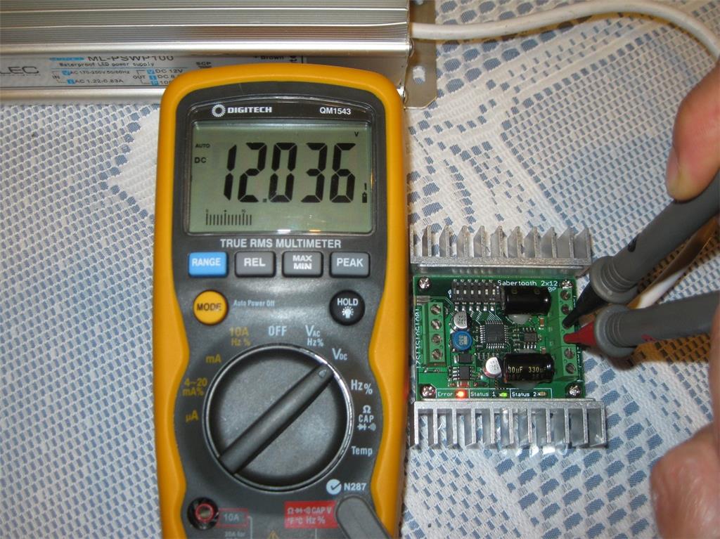
Load isn't the problem. Its a 2x12 Sabertooth and the motor draws only a couple of amps. The red light is on as soon as I turn on the power. I don't even get a chance to run the motor
Doesn't have to be the motor causing the over current. It could be a short in your wiring causing the sabertooth to shutdown?... If not maybe the sabertooth has "given up the ghost"? Re check your wiring... disconnect the motor leads at the sabertooth side and see if the red light goes out or not...
I have unplugged the motor and the red light is still on stress
Okay now I'm even more depressed, I have absolutely nothing connected to the Sabertooth except for the 12 volt supply..... Red light remains. I then removed the Kangaroo in case that was causing the issue........... red light still comes on. tired I'm thinking the Sabertooth has met its maker
Magic Smoke ... The great Sabertooth spirit has left the building.
Steve, it very hard to kill the Tooth. You may still be ok. Recheck all the dip settings on the Sabertooth and the Roo. I once hooked up a Roo without setting the Tooth's dips and got a solid red led. Taking the roo off with the dips set a certain way may cause a red led also but I'm not sure.
Also make sure your motor is working and not damaged, recheck all your wiring and connections. Without a complete and working circuit you may also get a red led. Did you accidentally swop the input power input wires? That will kill your Tooth dead.
Hope you find the issue. If we lived closer I'd send you a new 2x12 Tooth. I've got 6 new one's sitting here that I never used because I upgraded to the 2x32. I wanted to get away from having to use the dump battery for the regeneration power off of the tooth.
Well it seems I've managed to make something hard to do look easy.... but not in a good way.
I have checked all the wiring and there is no shorts. I have taken the radar off and run the motor with a battery, that works fine. The motor is rated at 5 amps stall current and 0.3 amps free run when supplied with 12 volts. I tested it with a 6 volt battery and it drew about 0.3 to 0.4 amps while turning the radar for load. The Sabertooth is rated for 12 amps and 25 amps peak so that motor load is well within its capabilities.
Whats strangest is the radar motor has been working fine for a while, I got a good tune first shot, set the ramping parameters with the Dimension Engineering software, and it was working great. I haven't touched the connections to the motor or the sabertooth, It simply just stopped working.
I don't know if this could have caused the problem, but I have just tested the battery I use for dumping the re-gen power into. Its a sealed lead 12 volt battery. I just measured it and it's only putting out 5.5 volts, so along with the Sabertooth, it seems this battery is also buggered... (an Australian term for not working, or stuffed,....another Australian term with the same meaning). Could this buggered battery have caused the death of my Sabertooth?
This "buggered" battery is there for dumping re-gen power from the radar motor and the bubble lifter linear actuator. I have another battery the same in the leg section for the sabertooth that runs the waist motor. I have three Saberteeth in total (I think that's the plural of Sabertooth ) The other battery is measured at about 11.5 volts at the moment. If the dump battery IS in fact the cause of the problem, I'm thinking I might have to upgrade all three Saberteeth to the 2x32 and use a resistor for the re-gen power to avoid future issues.
One question, If I do upgrade the Saberteeth, and re-use the existing Kangaroos, will they all need another auto tune?
Steve