
Lumpy
Canada
Asked
— Edited
Rotary Encoders - Looking For Suggestions
I think I'm going to bite the bullet and get a rotary encoder for my full-size R2 dome.
Anyone have some suggestions for one that will integrate with the EZ-B easily?
I basically want the dome to be able to return to center.
Let me know.
** Edit ** I have 3 places to mount. Slip-ring center / Motor / Main Gear.
Kris

No matter how hard you try, rotary encoders are not perfect. They'll skip counts often - which means the center of your dome will begin to change as it operates.
My suggestion is to use a POT, much like we had been discussing with Dave's B9. Have you seen that thread? Using the insides of a servo to control an HBridge... So essentially turning a motor/hbridge into a custom servo. That way you can actually use the servo controls in ARC. That also means being able to know the exact number of degrees the head has moved.
The last option is to use a simple switch. So when the head moves to the center, the switch is flipped. A little microswitch would work well. Or a reed switch. You'd need to put a little dimple on the slip-ring that pushes the switch in.
If you're still set on an encoder...... the last option would be to make a custom one. A really simple method would be to use the cheapest arduino you can find. You will only need 2 pins in use. When the number of counts of the encoder reaches the "Center" position, set the pin HIGH and the EZ-B can monitor that pin. It will know when the center is reached and tell the dome to stop turning.
You could do that with the EZ-B also, but there are so many other things it is doing... You'd need to dedicate a complete EZ-B just for rotary - and that's not a good use of it's time
hmmm... I'll take a look at Dave's B9 thread for this.
I thought this was going to be simple! ;-)
encoders kind of... suck they were a neat idea to use on the PONG arcade game in 1972. I know they were adapted to robotics in the 80's... But they weren't very useful. Most people, such as nolan bushnell, tried using wheel encoders for floor mapping on Androbot - and since then many other people have tried also.
The problem is the encoder is only good for wheel speed. Because you sample the speed of both wheels, and compare. You do that over and over and hope both wheels are working at the same speed. It won't give you accurate travel distance for 2 reasons. One, being the encoder misses steps often due to many reasons. Two, wheel slippage on the surface - specifically when turning.
So if you notice now days, roboticists avoid encoders and rely on IR positioning by beacon and camera.
The only people still using encoders are the very old style robots like Parallax's and Vex robots. Those companies sell 1990's technology and therefore confuse consumers. Many consumers come across robots (for example the disappointing Parallax BeoBot) and think "that is what robots are". EZ-Robot's goal is to change peoples perspective of what robots are and challenge companies to stop selling wheel encoders and start using current technology.
Our location positioning system that we'll be releasing this summer uses a camera.
As for your requirements, the best solution would be easily converting an HBridge into a servo. It's literally very very easy.
Thanks Dj for the latter explanation, I too was convinced implement encoders on the wheels, but now I understand that it is not good idea. Sometimes brainwash us with current technology supposedly, but wins his reasoning certainly overwhelming. Also I like to read different things like post and locate an "location positioning system that we will be launching this summer," Yes!
FROM info about using the pot accuracy is not great its mostly 10% off,read the specs on the pot ,some you can get at 1% but cost is very high ,and you need a pot that is a 360deg without a stop
Very high accuracy lasers (lidars) at about $1100 use magnetic encoders,usdigital has a lot of info on pots verses magnetic encoders.
NOW on your dome a pot is lower cost and would work well,since not using to measure distance or speed,
CAN easy check the internet to see if i am right or wrong.
Also you put on the last gear not the motor ,or the ratio with be off,check servo pan designs where they have the pot. Couple of other thing that some dont know about pots and magnetic encoders
On pots if you take them apart they have a wiper contact that wears out or gets dirty
On magnetic encoders way the are made is a small round magnet they doesnt wear out and has a hall effect sensor to detect the gauss output of the manget that never changes.
COST of most pots are about $5 compare to magnetic encoder of $40
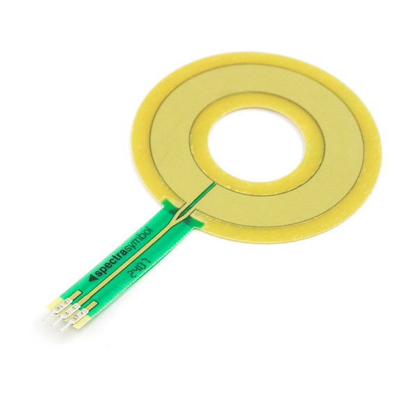
Did some browsing on the R2 forums. Found another user using one of these.
HotPot
It's been running good for the last 2 years for him. I'll give it a try. It will mount perfectly around my slip-ring and I can drill and tap the dome plate for the wiper/actuator.
$19 bucks. I'll give it a whirl.
That should work only the contacts would be hard ,second you need it in a dust proof container.
BUT a $15 or less, pot would be much more easy to use then that and a lot less work.